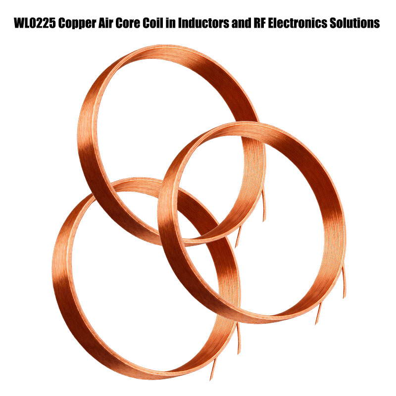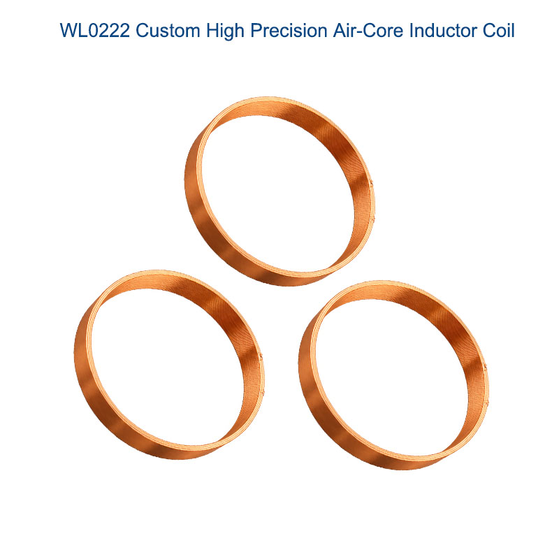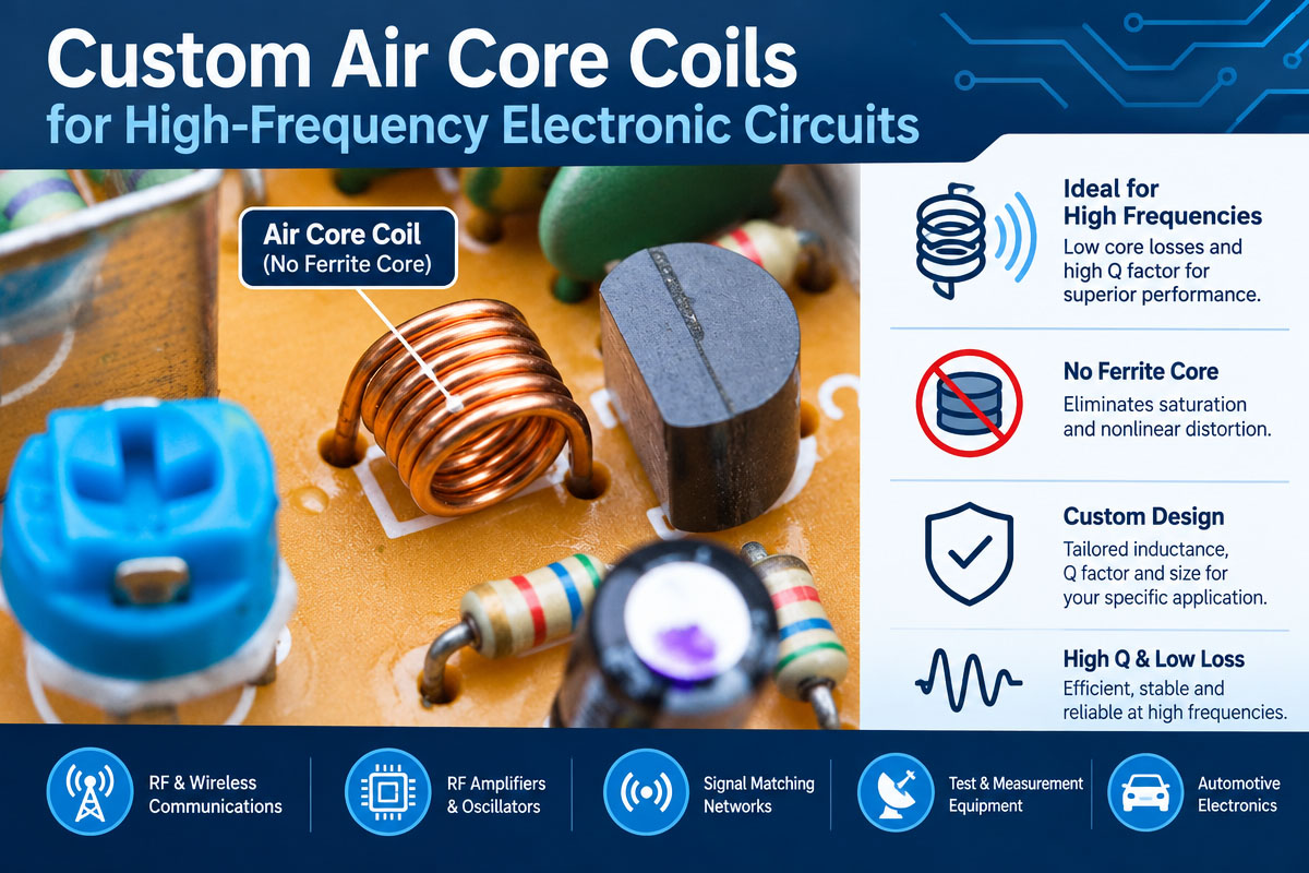
The elements of the inductive circuit working in high-frequency electronic circuits should have predictable electrical behavior, minimal parasitics, and stability of the work over a frequency range. For many applications in RF and communication electronics, power electronics, sensors, and wireless technology, custom air-core coils can provide more design freedom than standard inductors.
The Custom Air Core Coils (as opposed to the magnetic core inductor) do not contain magnetic cores and use air or any other nonmagnetic material as the effective core. It allows the avoidance of core saturation and helps engineers to get stable inductance characteristics for the high-frequency range. However, the creation of an air-core coil is more complex than just the selection of the wire diameter and turn number. The performance of the custom air core coils depends on the coil geometry, the conductor material, the winding technique, frequency, current, temperature, and parasitic capacitance.
The OEM buyers and electronic engineers can collaborate with a professional custom air core coil manufacturer in order to convert their electrical requirements to the manufacturable part. This guide contains information on the design considerations, the customization options, the manufacturing process, the testing requirements, and sourcing questions that buyers have to pay attention to while designing air core coils for high-frequency circuits.
1. What are custom air core coils?
The custom air core coils are an inductive device where the magnetic field is created mainly due to the coil winding without the magnetic or ferrite cores.
The air core, being not equipped with the magnetic core, has the following features that can be beneficial for the high-frequency circuits:
No saturation of the standard magnetic core
Minimal losses associated with the core
Possibility for high-frequency operations
Coil shape that can be adjusted
Modification of inductance by the winding design
Good Q factor if properly designed
Suitable for RF and resonant circuits
Custom air core coils are air core coils that were especially designed to meet the electrical, mechanical, environmental, and production requirements of a certain application.
As an OEM customer, a company can specify all the operating requirements instead of selecting the standard product with a specified inductance.
2. Why Should I Use Custom Air Core Coils in High-Frequency Circuits?
The operation of the high-frequency circuit is considerably different from that of the low-frequency circuit. The parasitic capacitance, skin effect, proximity effect, self-resonant frequency, and dielectric losses play a more important role.
Depending on the material and the conditions of use, the standard magnetic core can have additional losses or nonlinear behavior. Air core design allows avoiding the limitations of the magnetic materials.
The most common applications are:
RF communication devices
Matching circuits for antennas
Wireless communication systems.
RF filter
Resonant circuits
Oscillators (s
Tuner
High frequency amplifiers
Inductive sensors
Systems for wireless power.
Medical electronics
Test & Measurement Equipment
Industrial control electronics
The Custom Air Core Coils design can be desirable for applications requiring stability of the frequency and predictable inductive behavior.
3. Important Information Buyers Must Provide for Custom Air Core Coil Manufacturer
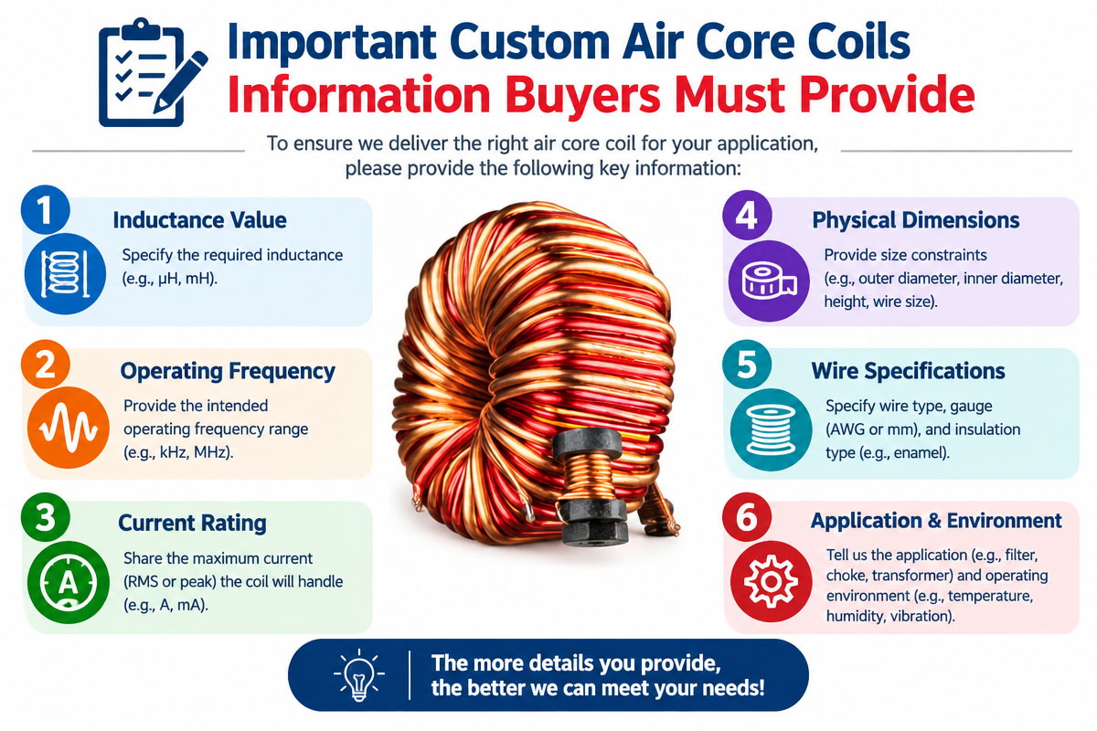
The buyer has to collect the electrical and mechanical specifications of the required custom air core coils before approaching the manufacturer.
The better the information provided by the buyer, the more accurate the manufacturer’s design review.
3.1 Required Inductance
Inductance is usually the initial point in the design of the coil.
Please specify.
Inductance (nominal)
Inductance tolerance
Measurement frequency
Condition or test voltage
Temperature range
In case of the high-frequency applications, the measurement frequency has to be specified. The inductance measured at 1 kHz cannot show the real behavior of the coil in the MHz or GHz frequency range.
3.2. Frequency of Operation
The frequency greatly affects the coil performance.
The manufacturer has to know:
Operating frequency (normal)
Minimum frequency
Maximum frequency
Frequency range requirements
Resonant frequency requirements
The above information allows evaluating the winding structure for parasitic capacitance and the self-resonant frequency.
3.3. Q-Faktor
The quality factor (Q-factor) is the important parameter for many RF applications.
For the defined test conditions, the higher the Q-factor, the less energy loss compared with the stored magnetic energy.
However, the Q-factor is frequency-dependent. Thus, the buyer has to specify the frequency at which the Q-factor is required.
The requirement “Q≥100” is incomplete if there is no indication of the frequency and testing method.
3.4. Current
Current requirements affect the conductor choice and the thermal properties.
Give:
Direct current
Peak current
RMS current
AC current (if applicable)
Duty cycle
The air core coil does not have a magnetic core saturation problem, but the conductor of the winding has electrical resistance and thermal limits.
4. Coil geometry and inductance
Coil geometry greatly influences the inductance and high-frequency behavior of the coil.
The main geometric parameters are the following:
Diameter of coil
Length of wire
Number of rotations
Wire thickness
Spacing between turns
Winding pitch
Inner diameter
Outer diameter
Lead length
Terminal config
The larger number of turns increases the inductance. The change in coil diameter or winding length changes the inductance and the distributed capacitance.
Not always the maximum inductance is the goal in high-frequency designs. The manufacturer has to balance the inductance, Q-factor, parasitic capacitance, physical size, resistance, and self-resonant frequency.
4.1 Self-Resonant Frequency
Self-resonant frequency (SRF) is one of the most important concepts in the high-frequency design of the coil.
An ideal inductor has only the inductance, but a real coil has distributed capacitance between the turns and other conductive structures. The combination of capacitance and inductance leads to the resonance if the frequency is high enough.
The component may not behave like the ideal inductor that the circuit engineer expects above or near the self-resonant frequency.
Thus, the buyer has to specify the required frequency of operation and, if necessary, minimum SRF.
The high-frequency Custom Air Core Coils can greatly benefit from the optimization of the winding structure that minimizes parasitic capacitance and guarantees good performance in the desired frequency range.
4.2 Conductor Choice of Custom Air Core Coils
The conductor is another important parameter in the design.
Typical conductors are:
Enameled copper wire
Silver-plated copper wire
Litz wire for corresponding frequency ranges
Special conductors for high frequencies
The copper is widely used as a conductor because of its high conductivity and convenient manufacturing.
For the high-frequency applications, the skin effect has to be taken into account. The current distribution in the conductor depends on frequency and may increase the effective AC resistance.
The wire diameter has to be selected depending on frequency, current, coil dimensions, thermal conditions, and Q-factor.
4.3 Winding Structure of Custom Air Core Coils
The winding structure may have a considerable influence on high-frequency performance.
The possible structures are:
Single-layer winding
Multi-layer winding
Tight wind
Windings, spaced
Helical winding
Basket or special winding structures
The single-layer spaced windings can be useful for some high-frequency applications in reducing the distributed capacitance. The multi-layer designs can provide high inductance in the small volume.
The optimal winding structure depends on the application and is not a universal parameter.
The manufacturer has to consider the electrical requirements and the installation space.
4.5 Mechanism Adaptation of Custom Air Core Coils
An OEM coil project is not the electrical performance alone.
And the coil has to be fitted in the customer’s equipment too.
The possible mechanical requirements are:
Maximum outer diameter
Maximum height
Growth dimensions
Terminal location
Lead wire length
Type of the connector
Insulation required
Encapsulation or Adhesive
Installation Method
Weight limits
For the compact electronic equipment, a few millimeters’ difference in the dimensions can affect the final assembly.
The 2D drawing or 3D model can be helpful for communication between the customer and manufacturer.
4.6 Custom Air Core Coils’ Temperature Requirements
The temperature can influence the resistance, inductance, insulation, and mechanical stability.
The buyer has to specify:
Operation temperature
Storage temperature
Temperature cycling specifications
4.7 Maximum allowable temperature rise
The resistance of copper grows with temperature, which can influence the losses and Q-factor.
If the coil is installed close to the power semiconductors, motors, transformers,. or any other heat source, the local temperature can be significantly higher than the general ambient temperature.
Thus, the manufacturer has to consider the overall thermal environment, not only the nominal room-temperature condition.
5. Custom Air Core Coils’ Protection and Insulation
Additional protection can be required for air-core coils depending on the application.
Some protection types are
Enamel coating
Sleeving.
Heat shrink tubing
Epoxy coating
Encapsulation.
Holders or spools (plastic)
Custom insulation structures
The chosen protection has to be suitable for the operating temperature and electrical requirements.
For RF applications, the parasitics may be influenced by the excessive dielectric materials near the winding. Thus, the insulation and encapsulation have to be considered in the electrical design, not only in the mechanical part.
6. Manufacturing Process of Custom Air Core Coils
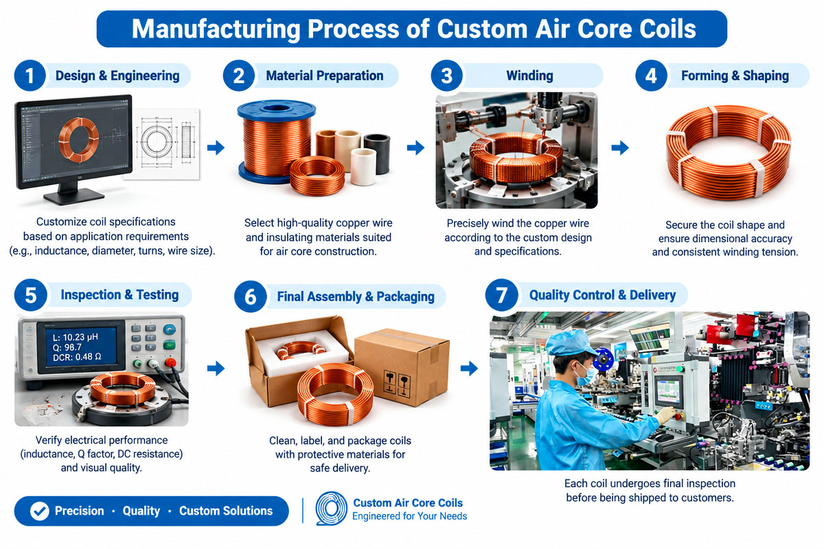
Talking about custom design, the professional coil manufacturer usually performs the following steps.
Step 1: Requirements analysis
The customer provides the electrical specifications, mechanical dimensions, environmental conditions, and production volumes.
Step 2: Design Engineering
Engineers evaluate the wire diameter, number of turns, coil dimensions, winding pitch, conductor material, and expected electrical performance.
Step 3: Prototype Development
The winding process creates the first prototypes.
Step 4: Electrical Test
Prototype parameters such as inductance, resistance, Q-factor, and self-resonance behavior are measured.
Step 5: Check in the Application
The customer checks the coil in the actual electronic circuit.
Step 6: Fine-Tuning the Design
The winding structure, wire, dimensions, or insulation can be changed if needed.
Step 7. Production Validation
When the design is approved, the production process and standards are established.
Step 8: Large-Scale Production
The approved design is produced in accordance with the agreed specifications and quality requirements.
This design process is especially beneficial for OEM customers, as it gives a clear path from the concept to production.
7. HF Coils Test Requirements
The tests have to be derived from the requirements of the application.
Typical measurements are:
L Inductance
Inductance has to be measured at the specified test frequency and conditions.
DC Resistance
DCR informs about the conductor resistance and can help to diagnose the winding or connection defects.
Q-Factor
The Q factor is especially important in RF and resonant applications.
Self-Resonant Frequency
Measuring the SRF allows defining the frequency range where the coil can act as an effective inductive element.
Insulation resistance
The resistance of the insulation of insulated or encapsulated coils can be tested at the request of the customer.
Withstand Dielectric Voltage
In case of a requirement, the dielectric withstand voltage can be used for checking the performance of electrical insulation.
Dimension Check
The dimensions, such as diameter, height, winding length, terminal location, and lead length, have to be checked according to the approved drawing.
Coil Manufacturing Quality Control
Moving from prototype to large OEM volumes, the quality consistency becomes more important.
The competent manufacturer has to develop the controls for:
Copper wire (incoming)
Wire Gauge
Insulation
Winding tension
Turn count
Winding dimension
Terminal connection
Welding or soldering
Encapsulating.
Electrical test
Final check
“Automated or semi-automated winding and testing equipment can ensure the repeatability of production.”
The customers can also ask for the inspection reports or production test records for critical applications.
8. How to Select a Custom Air Core Coil Manufacturer
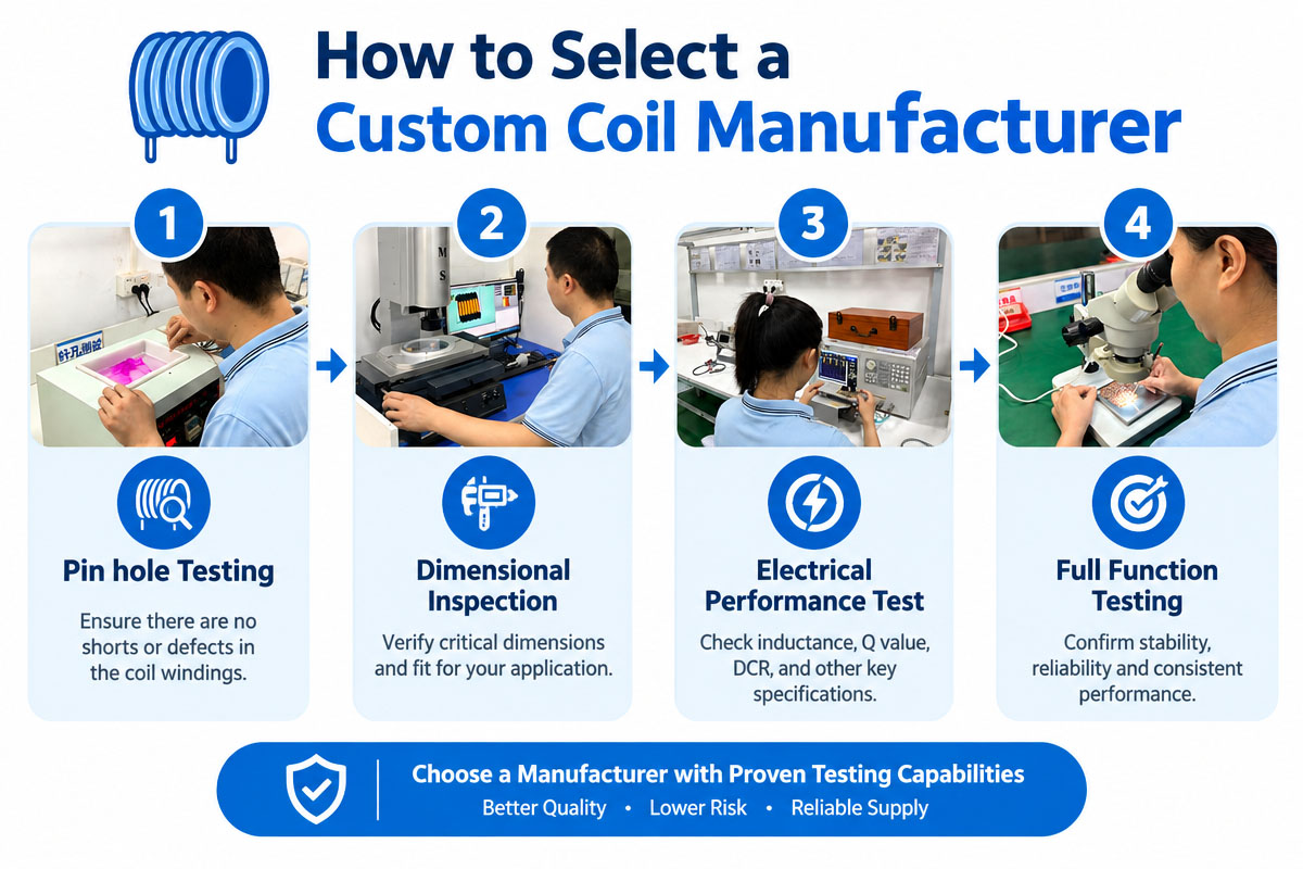
In selecting a manufacturer, unit price is not all you should compare.
Buyers need to consider:
Engineering Capabilities
Do they understand your frequency, inductance, your Q, your current, and your mechanical requirements?
Prototyping Capability
This is the ability of the supplier to deliver prototypes of the coil fast enough to test the circuit.
Winding Capability
Are the manufacturers equipped with the right tools to make coils of the specified diameter of wire, winding structure, and volume of production?
Ability to test
Are the manufacturers able to test the right parameters according to the application?
Customization
Are the manufacturers able to make changes in the dimensions, terminal shapes, winding pitch, wire size, insulation, etc.?
Quality Control
Are there documented inspection and production control processes by the manufacturers?
Production Capability
Can the suppliers make prototype quantities and also meet the future projected demand of mass production?
9. What Information Do You Need to Quote?
To get a faster and more accurate quotation, the following information is needed:
Required Inductance
Tolerance of inductance
Frequency of operation
Q-factor considerations
Maximum DC resistance
Current Requirement
Size of the coil
Specifications of the wire, if available
Number of turns if known
Operating Temperature
Insulation specifications
Terminal shape
Application and its functionality
Projected Quantity Per Year
Prototypes (number)
Indicate the circuit application and available space if some specifications are not provided. An experienced manufacturer can give suggestions on starting the design.
10. Factors Affecting the Cost of Custom Air Core Coils
The price of custom air-core coils depends on a number of factors.
These may include:
Copper Wire, type
Wire Diameter
Turns
Size of Coil
Degree of complexity of turns
Terminal shape
Insulation material
Encapsulation
Tooling and Fixtures
Test Requirements
Production Quantity
Package Requirements
The cost per unit in the prototype stage is usually relatively high since the cost of engineering setup and production preparation is distributed among a small quantity.
It might be possible to optimize the production process in order to reduce the cost per unit while maintaining the desired electrical and mechanical specifications for higher volumes of production.
11. Applications of Custom Air Core Coils
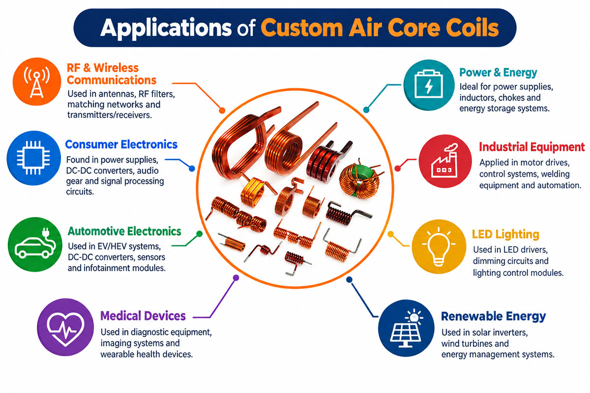
Custom air-core coils can be made to work in high frequency and used in many industries.
Common applications
Radio communication module
Wireless technologies
Antenna circuits
RF filter
Signal processing equipment
Sensors in the factory
Medical electronic equipment
Car electronics
Testing equipment
High-frequency circuits
Resonant converter
Wireless Charging systems
The design of the coil needs to match the electrical circuit and operating environment.
12. Conclusion
Custom Air Core Coils gives engineers and OEM buyers a flexible method to meet their high-frequency inductance needs. The lack of a conventional magnetic core enables these coils to avoid core restrictions and give design freedom in RF and high-frequency electronic applications.
The successful design of the coils requires careful considerations of inductance, frequency, Q-factor, self-resonant frequency, conductor selection, winding geometry, current, temperature, insulation, and mechanical dimensions.
The best design process for OEM applications is to start with the specifications, proceed to engineering design, prototype manufacture, electrical testing, application verification, and controlled mass production.
Buyers will be able to provide more technical information while requesting a quote. In case the exact winding geometry is not finalized, provide the circuit requirements, frequency, required inductance, current, available space, and application environment. Then, a good manufacturer will be able to analyze the requirements and work with their engineering team to come up with a viable design solution.
13. Frequently Asked Questions Custom Air Core Coils
1. Why do I use custom air core coils instead of standard inductors?
Buyers will be able to determine the inductance, dimensions, frequency characteristics, winding geometry, terminals, insulation, and other parameters according to the actual application using custom coils. It is especially useful when standard inductors cannot meet the required electrical or mechanical specifications.
2. What is the self-resonant frequency, and why is it important?
Self-resonant frequency is the frequency at which the inductive behavior of the coil couples well with the parasitic capacitance. Normally, operating frequency needs to be considered in relation to the coil’s SRF in high-frequency circuits.
3. Are Custom Air Core Coils available in minimal sizes?
Yes, we can make customized dimensions of the coil. However, reducing the physical size can influence inductance, resistance, Q factor, current capability, and producibility, and these parameters have to be analyzed.
4. Can I ask for a particular wire diameter?
Yes. Buyers can either give a preferred wire diameter or allow the manufacturer to choose one according to frequency, current, resistance, temperature, and mechanical considerations.
5. Is an air-core coil suitable for RF applications?
Yes. Air core coils are commonly used for RF and high-frequency applications where the use of magnetic-core components is not recommended due to core losses, saturation, parasitic effects, or frequency characteristics.
6. What test should I request before going into mass production?
Buyers can ask for inductance, DCR, Q-factor, SRF, dimensional check, insulation resistance, dielectric withstand test, etc., according to the application. The test criteria has to be clearly defined prior to production approval.
7. How do I reduce the cost of a special air-core coil?
Provide full specifications, optimize the coil geometry, do not require too much tight tolerance, and select feasible materials and realistic production quantities. Higher quantities of production can also help to recover tooling and setup costs.
8. What should I look for in a custom air-core coil manufacturer?
Compare engineering capability, high-frequency testing, winding technology, prototyping support, quality control, customization capability, production capability, lead time, and total cost of project. Not just the price of the first unit.