
Chapter 1: Custom Flat Air Coils Introduction
Custom air coils are designed using two practical questions that need to be answered: how many turns will fit into the available space, and what turn pitch is to be used?
The answers to these questions have implications not only in terms of the winding geometry but also affect the inductance, conductor length, DC resistance, current-carrying capabilities, magnetic field distribution, parasitic capacitance, thermal characteristics, and final dimensions. Even small pitch errors, accumulated over the number of turns, can significantly affect the final dimensions.
Thus, the most practical approach for the designer or OEM buyer would be to consider the custom flat air coils as a geometrical entity. The outer diameter, inner diameter, conductor size, insulation, number of turns, and spacing can’t be defined independently from each other. This guide provides the practical approach to determine the turn count and pitch of custom flat air coils. Formulas, an example, design trade-offs, and production checks are provided.
Chapter 2: What is a Flat Air Coil?
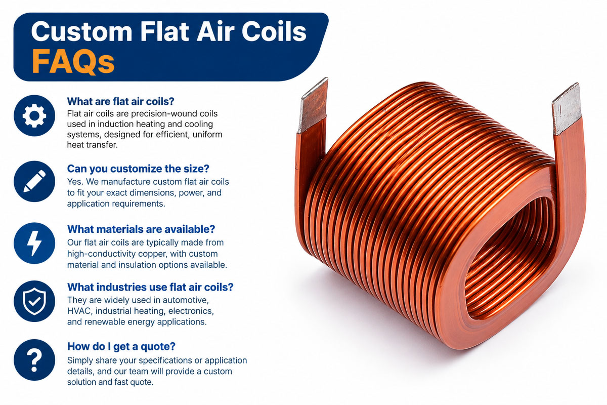
Custom flat air coils are planar or nearly planar windings created without a ferromagnetic core in the magnetic path. The conductor can be circular, oval, square, rectangular, or even an application-specific spiral made from round magnet wire, rectangular wire, flat copper wire, or foil.
Due to the mainly air magnetic path, the geometry greatly defines the electrical characteristics. The applications include wireless power transfer, sensing and detection, electromagnetic actuators, antennas, test equipment, medical devices, industrial electronics, and automation.
Most of the published studies of planar spirals describe the spiral by means of the number of turns, conductor width, turn spacing, and inner or outer diameter. All of the above parameters also provide a good starting point for the analysis of custom flat air coils, although the wound products might require another electrical model compared to the integrated planar inductors.
Chapter 3: Why the Count and Pitch of Turns Matter
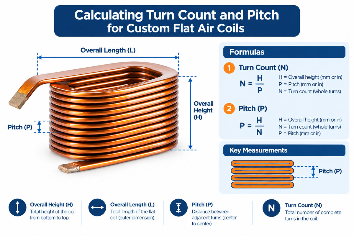
Turn count: The number of full turns of the conductor in the winding. Pitch: the radial distance between the centers of adjacent turns.
In order to place more turns within a fixed radial space, either the narrow conductor or a smaller gap is required. Increasing the pitch with the conductor size unchanged will result in a reduction in the number of turns placed.
In general, an increasing turn count of custom flat air coils will result in the increase of inductance. However, this increase is associated with the increase of the conductor length and resistance. The pitch is a parameter that shows how close the turns are. The smaller the pitch, the more compact the winding; the greater the pitch, the more separation and the more radial area.
Thus, the goal is not to maximize the number of turns only. It is required to develop the correct
geometry that will satisfy the electrical, thermal, dimensional, and manufacturing requirements.
3.1 First, define the coil geometry.
Define the methods for measuring each dimension in order to perform the calculations of custom flat air coils.
These symbols will be used below:
Dout = outside diameter of the completed winding;
Din = inner diameter of the last winding;
w = radial width of one insulated conductor;
s = spacing between adjacent insulated turns;
p = pitch (center to center);
N = number of turns;
B = available radial winding width.
For a flat circular spiral:
B = (Dout − Din)/2
Pitch is:
p = s + w
If the insulated conductor is 1.5 mm radially and the gap is 0.3 mm, the pitch will be 1.8 mm.
For checking of the physical fit, the finished insulated wire diameter is used for round wire. For rectangular or flat wire, the radial dimension should be considered. Also, do not forget to account for adhesive, tape, coatings, and process clearance.
3.2 Calculation of Turn Count
Having the information about the outside diameter, inside diameter, conductor width, and spacing, the approximate maximum number of turns is
N = 1 + (B – w)/p
Because:
B = (Dout – Din) / 2 and:
p = w + s
3.3 The formula can also be written as
N = 1 + {[(Dout − Din) / 2] − w} / (w + s)
The answer does not necessarily need to be an integer. In most practical windings, round the number of turns down and check the remaining clearance.
The reason for the “+1” is evident from the radial build formula:
Bcoil = w + p(N-1)
The first turn occupies one conductor width. Each additional turn adds one pitch.
If the custom flat air coils have the lead exits, terminals, crossover insulation, or other manufacturing constraints, avoid filling each millimeter of the space available and leave some margin for manufacturing purposes.
Chapter 4: The Custom Flat Air Coils formula to calculate pitch
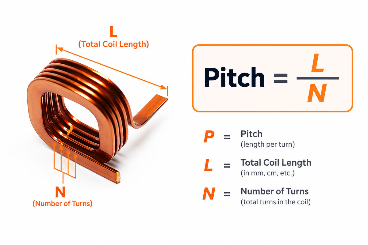
If the number of turns is known, then the pitch that would be required to spread those turns across the available radial width is
p = (B – w) / (N – 1)
And then calculate the clear spacing:
s = p – w
For example, for a radial width of 20 mm, a 1.0 mm conductor and 11 turns:
p = (20 – 1) / (11 – 1) = 1.9 mm
The apparent gap is
s = 1.9 – 1.0 = 0.9 mm
For custom flat air coils, these should be considered as nominal dimensions. The drawings for manufacturing purposes should include tolerances.
4.1 Worked Example: Turn Count and Pitch Calculations
Consider custom flat air coils with the following target dimensions:
Outside diameter: 80 mm
Inner diameter: 30 mm
Insulation thickness of the conductor radials: 1.6 mm
Desired clear spacing: 0.4 mm
Calculate the radial winding width first: B = (80-30)/2 = 25 mm
Then calculate the pitch:
p = 1.6 + 0.4 = 2.0 mm
Now calculate the theoretical number of turns:
N = 1 + (25 − 1.6)/2.0 = 12.7 turns
12 full turns. Check.
Bcoil = 1.6 + (12 – 1) * 2.0
Bcoil = 23.6 mm
The 25 mm radial space contains twelve turns with 1.4 mm allowance.
Now check 13 turns:
Bcoil = 1.6 + (13 – 1)(2.0)
Bcoil = 25.6 mm
Thirteen turns occupy too much space. Therefore, the practical maximum at the pitch of 2.0 mm is 12 full turns.
If the 12 turns are to be distributed evenly over the 25 mm radial width, then:
p = (25 – 1.6) / (12-1) p = 2.127 mm
The nominal clear gap will read:
s = 2.127 – 1.6 s = 0.527 mm
This shows the utility of both formulas in the development of custom flat air coils. One allows calculating the number of turns for a given pitch; another calculates the pitch for the required number of turns.
Chapter 5: Centerline Dimensions vs. Edge Dimensions
A frequent mistake in calculations is to confuse centerline dimensions with the conductor edge dimensions.
If the inner and outer diameters are defined at the edges of the conductor, then use the above radial-build formulas.
If the drawing defines the radius of the inner and outer turns, then use:
rout,c – rin,c = (N – 1)p (
N = 1 + (rout,c – rin,c) / p
Both approaches are correct, but they shouldn’t be used together.
The drawings for custom flat air coils should include unambiguously whether the dimensions are defined at the conductor edges, conductor centerlines, tooling boundary, or finished encapsulated dimensions.
This becomes especially important for close dimension tolerances. If the supplier calculates the winding with the inner diameter as an edge dimension when the designer intended it as a centerline dimension, it might result in the winding with a different turn count or outside diameter.
Chapter 6: How Turn Count Influences Inductance
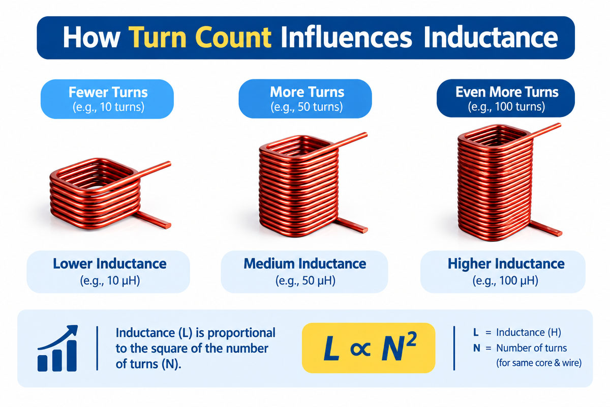
The turn count is usually selected to achieve the desired inductance and not just to fill the available space.
The inductance normally increases rapidly with the increase in turns. However, in a flat spiral, more turns also change the average diameter, fill ratio, conductor length, and mutual coupling.
Therefore, the assumption that the inductance depends only on the turn number could be incorrect.
In the models of planar inductors, parameters like turn number, average diameter, and fill ratio are considered. Mohan and co-workers analyzed a design range where their approximations of the spiral inductor agree with field-solver calculations within a few percent. However, they were dealing with integrated planar inductors; therefore, the custom wound coils should be modeled considering their actual conductor dimensions and geometry and should be validated experimentally.
A practical engineering approach in the development of custom flat air coils would be to define the physical geometry, estimate the inductance by means of an appropriate model, create a prototype, and measure the finished coil at the required test frequency.
This is especially important since the inductance measured at one frequency may behave differently at another frequency.
Chapter 7: The Effect of Pitch on Electrical Performance
Pitch is not just a mechanical specification.
Pitch: reducing pitch brings the adjacent turns closer. Increased density and magnetic coupling, but also increased electrical interaction between adjacent conductors and parasitic capacitance.
Increased pitch will make the separation larger. But it will also increase the size of a coil with a certain number of turns or reduce the number of turns that can be made within the allowed envelope.
Therefore, the ideal pitch of custom flat air coils is the function of the frequency and available space.
With low frequencies, resistance, current rating, inductance, and temperature rise may play a more dominant role.
With high frequencies, other factors become more important, among them:
Skin effects
- proximity effect
- parasitic capacitance
- self-resonant frequency
- the shape of the lead
- the conductive materials around
The best electrical design is not necessarily the smallest pitch that can be produced.
Chapter 8: Conductor Size, Resistance, and Current Rating
Increased cross-sectional area of a conductor decreases its DC resistance. But a wider conductor will require more radial space.
This is one of the key design criteria for custom flat air coils.
Increased conductor sizes can help reduce copper losses and increase current rating. But they can also reduce the number of turns within the inner and outer diameters.
Define the shape of the spiral. Estimate the length of the conductor and resistance.
The radius of each turn varies. Detailed calculation should take into account the varying length of each turn. In addition, the length of the lead should be taken into account.
The simplified approximation will multiply the average circumference of a turn by the number of turns. Detailed turn-by-turn calculation using CAD or a similar technique is much more accurate.
At high frequencies, conductor losses include not only DC resistance. Additional losses can be caused by skin and proximity effects.
Chapter 9: Manufacturing Tolerances Matter

A winding can be mathematically ideal and difficult to produce.
The conductor dimensions have manufacturing tolerance. Insulation has thickness tolerance. The winding machine has positioning stops. Springback, pressure forming, adhesive flow, curing, and handling can change the dimensions of the finished part.
Therefore, custom flat air coils should take into account reasonable production tolerance, not every fraction of a millimeter.
According to theoretical calculation, it is possible to put 20.98 turns into the allowed space. But specifying 21 turns means there is no production tolerance left.
Depending on the application, important specifications may include:
- Outer Diameter
- Inner Diameter
- General thicknesses
- Number of turns
- Pitched
- Spacing between turns
- Lead
- DC resistance
- Inductance
- Electrical tolerance
Mechanical and electrical tolerances should be considered together.
Chapter 10: Common Mistakes in Calculation of Number of Turns and Pitch
The most common mistake when designing custom flat air coils is the usage of the conductor width instead of its finished dimensions.
Bare conductor dimensions can be used to calculate the conductor area and resistance. But the insulation occupies space. Ignore it and you get too large a number of turns that can fit.
Another common mistake is the treatment of pitch and gap as one dimension.
Do not forget:
Pitch = conductor width + spacing
Some designers try to round up the theoretical number of turns without redoing the calculation of the total radial build.
Another common mistake is optimizing custom flat air coils only for inductance. More turns = longer conductor. This adds resistance. This adds to copper losses and temperature rise.
The inner lead is another often forgotten aspect. It may or may not require a crossover, insulated bridge, additional layer, or special termination technique. This feature also requires some space and affects the electrical behavior of the coil.
Chapter 11: Practical Workflow of Coil Design
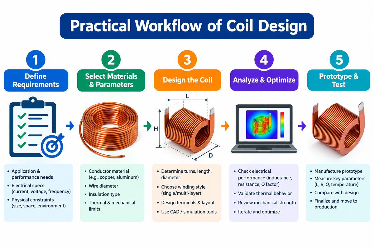
The design process of custom flat air coils is driven by the application, not by an arbitrary number of turns.
First of all, you should define the key criteria of the design:
- Inductance and test frequency objectives
- Maximum load resistance
- Operating current
- Operating frequency
- Outer Diameter
- Inside Opening
- Maximum thickness
- Duty cycle
- Temperature range
- Lead requirements
Chapter 12: Then select the appropriate conductor and insulation system.
Calculate the available radial winding width. Choose the initial gap. Calculate the pitch. Number of turns that fit. Estimate inductance, conductor length, resistance, current density, and thermal performance.
If the electrical performance is not on-target, add or remove turns, pitch, conductor dimensions, or inner/outer diameters.
After convergence of the design, make and test a prototype in the conditions that are as close as possible to the final application.
This is especially true when the custom flat air coils are used in the neighborhood of the conductive housings, magnets, shields, ferrites, or other materials that can affect the electromagnetics of the finished assembly.
Chapter 13: Conclusion
The calculation of turn count and pitch of custom flat air coils is based on the basic geometry, but good coil design requires integration of electrical, thermal, mechanical, and manufacturing criteria.
The basic equations of the calculation are
B = (Dout – Din)/2
p = w + s
Bcoil = w + (N – 1)p
N = 1 + (B − w)/p
p = (B − w)/(N − 1)
These equations describe the available radial winding width, conductor size, number of turns, pitch, and turn-to-turn spacing.
But the geometric fit is only the first step. The resulting design should be verified by the estimation of inductance, resistance, operating frequency, current capability, temperature rise, lead, and manufacturing tolerances.
Calculation is the first step in designing custom flat air coils. Modeling, prototyping, and measurement verify that the final winding will match the criteria of the actual application.
Chapter 14: Custom Flat Air Coils FAQs
1. What do you do to determine the number of turns in a flat air coil?
For dimensions defined on the edges, first calculate the available radial width B = (Dout – Din)/2. If w is the width of the insulated conductor and p is the pitch, N = 1 + (B – w)/p. Round down as needed and verify the radial build.
2. How to calculate the coil pitch?
Pitch is the distance between the centers of two successive turns. If the conductor width is w and the clear spacing is s, then p = w + s. If turn count and the available radial width are fixed, then use p = (B − w)/(N − 1).
3. Does the coil pitch equal the distance between the turns?
No. The pitch is measured from center to center of one conductor to the next. The spacing is the clear distance between the edges of adjacent conductors. For a uniform winding: gap = pitch – conductor width
4. What size wire should I use: bare or insulated?
Use finished insulated dimensions for physical winding fit calculations. Bare conductor dimensions are useful for resistance and cross-sectional calculations of copper, but insulation takes the actual space for the pitch and number of turns.
5. More turns always mean more inductance, right?
Additional turns increase inductance. But the exact increase depends on the coil geometry. The number of turns influences the average diameter, conductor length, resistance, magnetic coupling, and parasitic effects. Therefore, the last turn should be modeled and measured.
6. What is the optimal turn-to-turn spacing?
The optimal spacing depends on the conductor sizes, insulation, the operating voltage, target inductance, frequency, parasitic capacitance, thermal requirements, manufacturing capability, and available space. There is no universal gap that would work for all applications.
7. Why prototype after the calculation of custom flat air coils?
Nominal dimensions and simplified assumptions are used in the calculation. But measured performance can be influenced by the conductor tolerances, leads, surrounding materials, winding fixtures, manufacturing process, and frequency-dependent effects. Verification of the design is done by prototyping before mass production.
8. What information do I need to provide a custom coil maker?
Custom Flat Air Coil Inductors Specify the target inductance and test frequency, resistance limit, operating current and frequency, outside and inside dimensions, maximum thickness, conductor preference, turn count if known, lead and termination requirements, duty cycle, temperature range, operating environment, and expected production quantity.


