Chapter 1: Introduction
Air core coil winding is one of the most exact methods of manufacturing air core coils. Unlike the coils with iron or ferrite cores, the air core coil winding creates the magnetic field using winding. Due to the simplicity, air core coils provide good performances at high frequencies, have low losses, and have well-known electromagnetic properties.
Using Air Core Coils: The air core coils are widely used in RF circuits, antennas, wireless communication equipment, filters, sensors, power electronics, and other industrial applications. However, if you want to achieve high reliability of inductance and mechanical properties of the coil, it is a rather complicated issue.
The inductance, resistance, Q factor, and other parameters of the coil depend on many factors, such as wire diameter, turns count, winding pitch, winding tension, coil dimensions, insulation, and winding termination.
This manual describes the basic technologies and steps of the air core coil creation.
Chapter 2: What Is Air Core Coil Winding?
The coil winding is the process of formation of insulated conductive wire in the specific coil shape. The air core winding is the process of winding without the ferromagnetic or magnetic core inside the coil.
The most frequently used conductive materials are the enameled copper wires due to their good conductivity and wide variety of diameters. The conductors may have different shapes—round, rectangular, and others.
In the air core coil winding process, the wire is wound around the mandrel or winding fixture with a predefined number of turns. When the current is passed through this coil, which is wound in this way, it produces a magnetic field.
As you can see, this kind of coil does not use a magnetic core, and it allows avoiding many problems connected with core saturation and magnetic losses. Therefore, the air core coils are highly effective for high-frequency applications.
Chapter 3: The Importance of Precision in Air Core Coil Winding
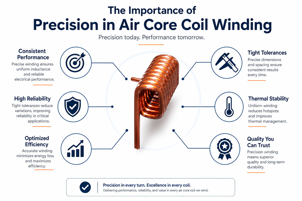
The principal of work is clear; however, the industrial air core coil winding is quite sensitive to variations in the manufacturing.
The important parameters include
Wire gage
Turns
Coil diameter (inner and outer)
Helix pitch
Coil length
Winding tension
Gap between turns
Orientations of winding
Lead length
Arrangement of connection terminals
Insulation type
For example, the turns number can be varied greatly to vary the inductance. The increase of the gap between the turns influences the parasitic capacitance of the coil.
Thus, the production requires accurate winding equipment and a controlled process.
Chapter 4 – Building of the Air Core Coil Winding Process
4.1 Definition of Specification
The electrical and mechanical parameters, which are necessary, have to be defined before winding air core coils.
The following are the examples of the specifications:
Inductance Target
Operating frequency
Current rating
Resistance Needs
Q factor (Q)
Wire Diameter
Number of turns
Coil Size
Tolerances Required
Operating Temperature
Terminal Specification
The operating frequency is an especially important parameter, since the spacing and geometry of the coil can be adjusted accordingly.
4.2 Selecting the Copper Wire
The wire selected will directly influence the electrical resistance, current-carrying capabilities, size of the winding, and quality of the insulation.
For the air core coil winding, the most frequently used wire is enameled copper wire. The thin insulation allows winding many turns in a small space.
The diameter of the wire should be chosen according to:
Current requirements
Resistance limitations
Available winding space
Required number of turns
Thermal environment
“Robustness”
The thin wire means the high resistance and low current-carrying capability. The thick wire makes it impossible to get the required geometry.
4.3 Winding Mandrel Preparation
The inner diameter of the coil is defined by the mandrel or winding former.
The dimensional accuracy and quality of the surface of the mandrel are very important during the air core coil winding process. The wire should be removed from the mandrel without damage to the insulation and deformation of the coil.
The material for the mandrel depends on the manufacturing method. The mandrels used by the manufacturers can be made of metal, engineering plastic, or special tool material.
Usually, in high-volume manufacturing, specialized tooling is used for getting dimensional accuracy and efficiency.
4.4 Defining Winding Parameters
The parameters required should be programmed into the winding machine before manufacturing.
The parameters include:
RPM
Number of passes
Strained wires
Travel speed
Pitch
Starting and ending points
Direction of rotation
Wire length
The particularly important parameter is the wire tension, which should be controlled. The excessive wire tension will stretch the wire and damage the insulation. The insufficient tension will make the turns loose or irregular.
Therefore, the tension control system is the key factor of air core coil winding.
4.5 Air Core Coil Winding
After preparation of the equipment, the wire is wound around the mandrel according to the specified winding pattern.
The following technologies of winding can be used by the manufacturers for winding the coils:
Close winding
Progressive coiling
Distributed winding
Single-layer winding
Multi-layer windings
For applications where dimensional accuracy and predictable high-frequency properties are important, the single-layer winding is preferable.
The winding machine should maintain the constant speed and wire tension during the winding of the air core coil. The operators or automated inspection system should control the coil for crossed turns, spacing, overlapping wire, or damaged insulation.
4.6 Fixing of Coil
When the required number of turns is done, the winding should be fixed to maintain the shape of the coil.
The manufacturers have the following methods to use depending on the application:
Glued
Thermal processing
Self-bonding glaze
Mechanical Fasteners 8.1. Introduction
Protective layer
This fixing method should not influence negatively the electrical properties or operating temperature of the coil.
4.7 Creation and Termination of the Leads
The beginning and ending wires should be processed according to customer requirements.
The following are the examples of the termination methods:
Exposed wire ends
Tinned leads
Soldered terminals
Crimp terminals
PCB mount terminals
The leads should be controlled, since the wrong configuration of leads causes assembling problems.
4.8 Inspection and Testing of Finished Coil
The air core coil winding is the process of quality control of the coil.
The following are the typical tests:
Inductance Test: Verifies that the coil is within its electrical values.
DC Resistance Test: Verifies the resistance from the wrong wire size, poor connections, or winding faults.
Visual inspection: Verifies winding consistency, insulation condition, positions, and physical dimensions of leads.
High-frequency test: The manufacturers can perform the test of Q factor, impedance, self-resonant frequency, and other properties for RF application.
Dimension inspection: Verifies the diameter, length, pitch, and position of terminals on the coil.
Chapter 5: Expert Tips to Improve Air Core Coil Winding Wire Tension Control
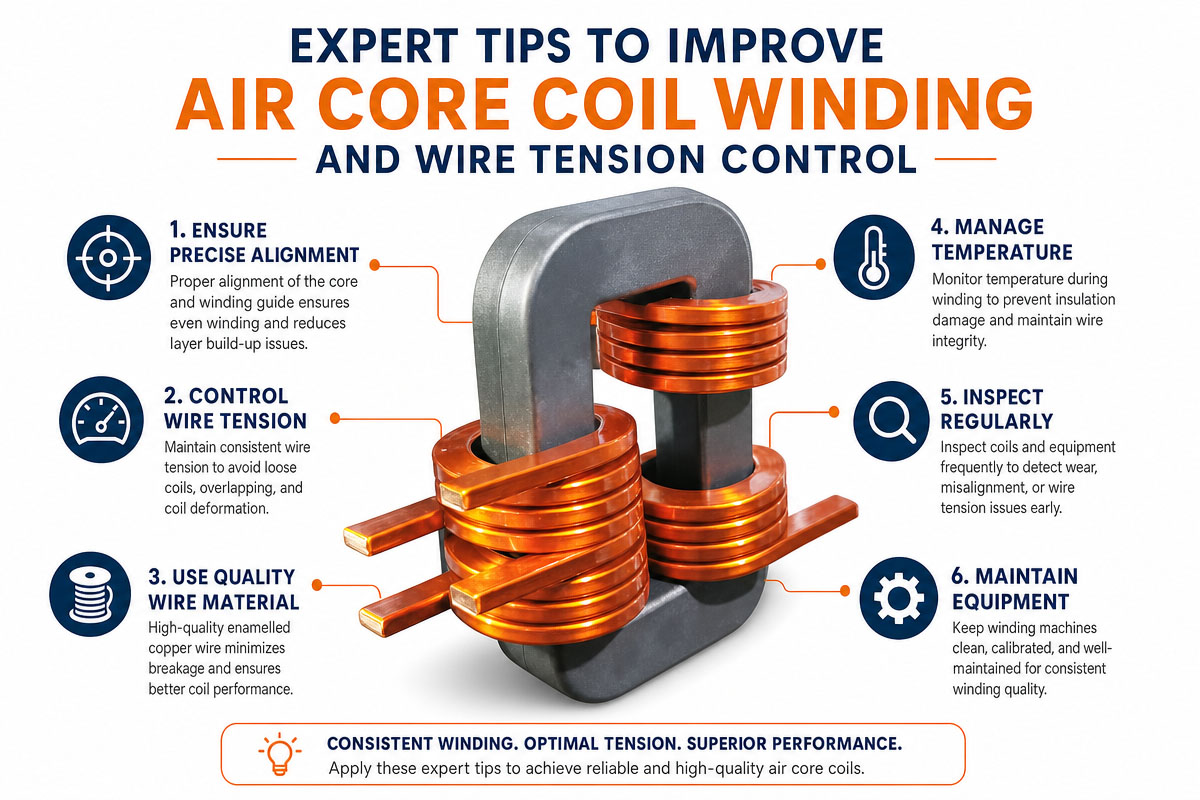
The important parameter of the air core coil winding is the constant wire tension. The automatic tension control system helps to minimize the coil-to-coil variation and deformation of the wire.
Turn Count Tracking Precisely
The turn count should be automatically controlled whenever possible. The error in the turn count can result in the out-of-tolerance inductance of the finished coil.
Winding Pitch Optimization
The electrical properties of the coil depend on the pitch of the turns. Tight winding allows obtaining small dimensions of the coil, while spaced winding decreases parasitic capacitance and improves high-frequency properties.
Using the Precision Tools
The precise mandrels and winding tools improve the dimensional uniformity of the coils. The specialized tooling improves the quality and efficiency of the custom industrial coils.
Wire Insulation Monitoring
This damage to the enamel can result in short circuits between the turns or problems with reliability. Therefore, smooth wire guides and tooling with appropriate contact pressure are required.
Chapter 6: Common Problems of Air-Core Coil Winding
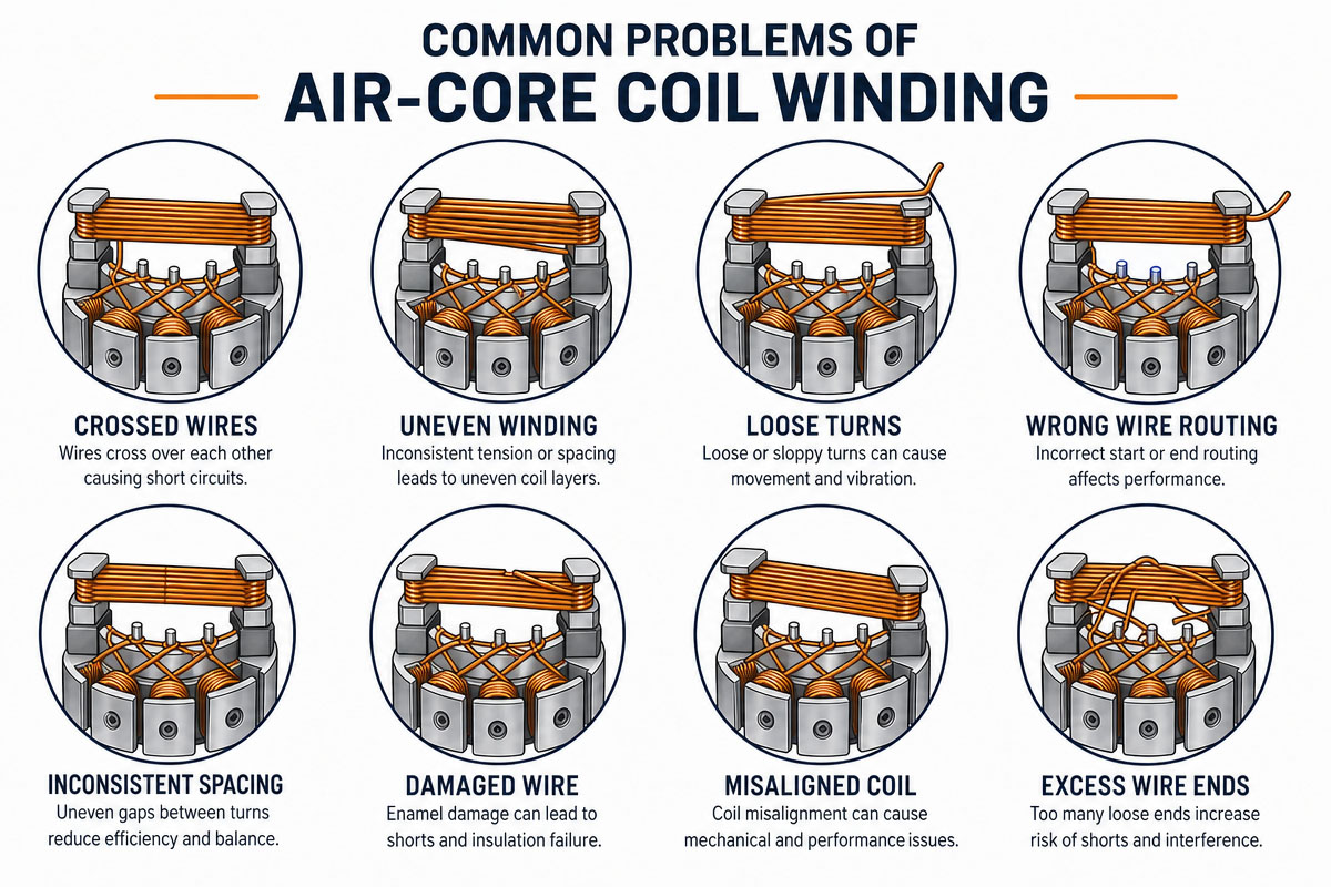
Turns Inegal
The uneven winding can be caused by the unstable wire tension, wrong pitch settings, or wrong machine calibration.
Solution: Check the tension system, traverse settings, and winding program.
Poor Inductance
Wrong turn count, coil dimensions, winding spacing, or wrong position of wire causes variation of inductance.
Solution: Verify all winding parameters. Check the coil dimensions after winding.
Torn wire insulation
The excessive tension, sharp tool edges, and rough wire handling can damage the insulation.
Solution: Minimize the mechanical stress. Check the wire path and winding tools.
Unraveling
Loose turns cause changes of the geometry of the coil and inconsistency of the electrical properties.
Solution: Increase the winding tension. Do not overtighten winding tension.
Lead Problems
The wrong lead length or position makes the automated assembly impossible.
Solution: Add lead dimensions and connection terminal requirements on the original winding drawing.
Chapter 7. Applications of Air-Core Coils
The high-quality air-core coil winding has a great number of industry applications.
RF and Wireless Communications
The RF filters, matching networks, oscillators, and antennas use air-core inductors.
Sensors
The coils are used for sensing changes in the electromagnetic environment. They are used in many sensors.
Automotive Electronics
The custom coils can be integrated into electronic control systems, communication modules, and sensors.
Biomedical Electronics
The special electronic equipment, which requires stable electrical properties, uses precision coils.
Power Electronics: Air core inductors are highly effective in some high-frequency power applications to avoid the limitations of magnetic cores.
Chapter 8: How to Select the Air Core Coil Manufacturer
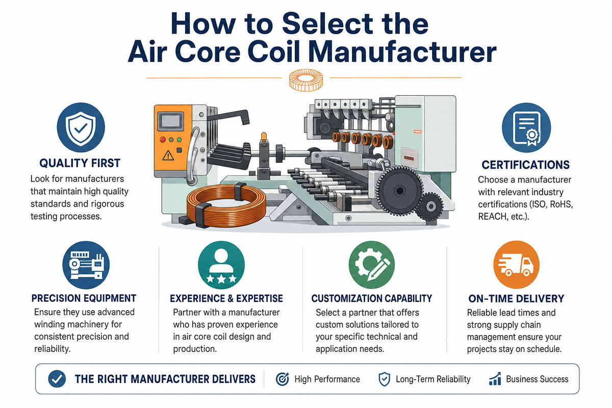
When you purchase the custom coils, do not pay attention to the price per unit.
Ask the manufacturer to supply you with the following information:
Wire size capacity
Winding diameter range
Accuracy of turn count
Tension control capacity
Inductance tolerance
High Frequency Test
- Inspection of dimensions
Prototyping capacity
Production capabilities
Quality control procedures
The manufacturer with air core coil winding equipment, precision tooling, testing equipment, and process control can provide high-quality products for demanding applications.
Chapter 9: FAQ of Air Core Coil Winding
9.1 What is air core coil winding
The air core coil winding is the winding of the insulated conductive wire in the coil without a magnetic core. It produces the coil. When the current is applied to this coil, the electromagnetic field is created.
9.2 Which wire is used for air core coil winding?
The most frequently used wire is the enameled copper wire, due to its high conductivity, flexibility, and compact insulation. The wire diameter depends on the current, resistance, and dimension requirements.
9.3 The effect of turn count on air core coil?
“The higher the turns, the higher the inductance generally. But the inductance of the last coil depends on many parameters, such as the diameter, the length, the spacing, and the geometry of the winding.”
9.4 Why is the tension of the wire important?
To ensure even turns and to maintain the same coil dimensions, the wire is kept at constant tension. If the tension is too high, it will damage or stretch the wire. If the tension is too low, the winding will be loose and uneven.
9.5 Are the air core coils customized?
Yes. The manufacturer can customize wire diameter, turns, coil size, winding pitch, lead configuration, insulation, and electrical properties for application requirements.
9.6 How to test an air core coil?
The usual tests are inductance, DC resistance, dimensions, visual inspection, insulation integrity, and high-frequency properties, such as Q factor and self-resonant frequency.
9.7 What industries use air core coils?
The air core coils are used in RF communications, antennas, sensors, automotive electronics, medical electronics, industrial controls, and other high-frequency circuits.
9.8 What causes the change of inductance in the air core coil?
The most frequent causes are inconsistent turn count, variations in wire diameter, wrong winding pitch, dimensional variations, unstable tension, and changes in coil geometry.
9.9 Winding Air Core Coils—Automatic or Manual Winding?
The manual winding can be used for prototyping purposes. The automated winding provides better consistency, accuracy of turn count, tension control, and dimensional consistency in the manufacturing.
9.10 What information do I need to give for making a custom air core coil?
Inductance needed
Tolerance
Operating frequency
Current
Wire diameter (if known)
Turns number (if known)
Coil dimensions
Winding pitch
Leads configuration
Operating temperature
Annual quantity. Technical drawings or samples can also be useful.
Chapter 10: Conclusion
The air core coil winding is a combination of electrical design and precise mechanical manufacturing. The turn count is only one of the parameters. Many others depend on the performance of the finished coil. The final result depends on such parameters as wire selection, winding tension, pitch, coil geometry, insulation, termination, and testing, etc.
The controlled winding process is required for prototypes and industrial production in order to get stable inductance, reliable mechanical dimensions, and electrical properties.
The sophisticated testing, accurate winding equipment, controlled wire tension, and designed tooling allow the manufacturers to produce air core coils for high-demand RF, sensor, automotive, communication, and electronic applications.