Skip image slider
Copper Air Core Coil Manufacturing Process Explained
Precision Copper Air Core Coil in Electronic Devices Guide
High-Q Copper Air Core Coil for Wireless Solutions
Copper Air Core Coils Design for Wireless Communication
Custom Copper Air Core Coils for Industrial Electronics
Copper Air Core Coil for High-Frequency Power System guide

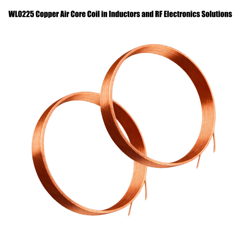
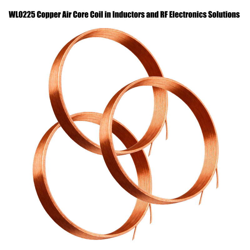
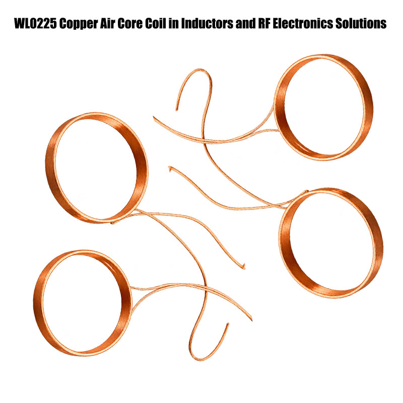
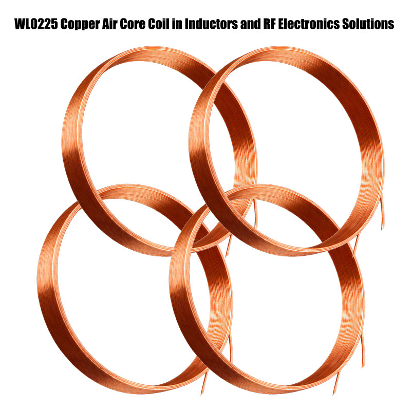
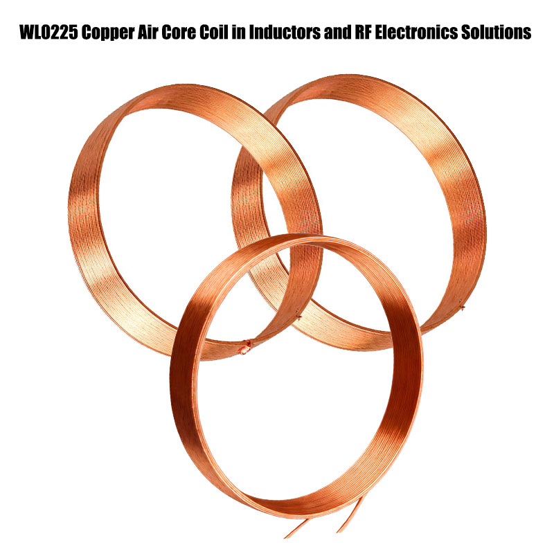
WL0225 High-Frequency Copper Air Core Coil for RF System Guide

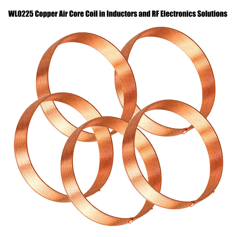
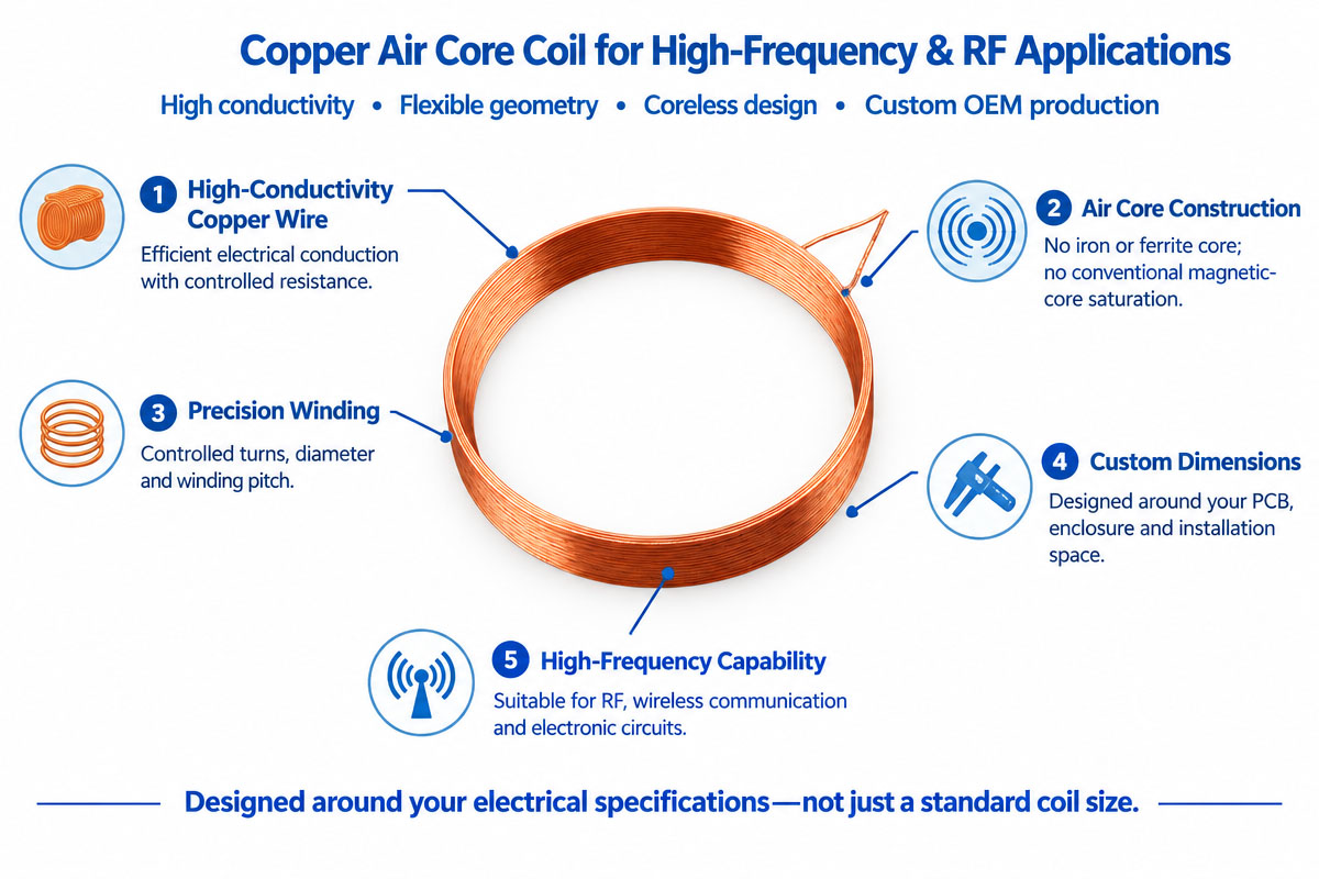
A copper air core coil is an electrical device that consists of a precision-wound coil and is used to produce inductance and magnetic fields without using iron, ferrite, or any other core material. The copper coil is usually made of the enamelled copper wire due to the high electrical conductivity and effective current flow. The air core construction is especially important in high-frequency applications where magnetic core losses, saturation, and frequency dependence can affect circuit performance.

Electrical properties of a copper air-core coil are defined by such parameters as wire diameter, number of turns, diameter of the coil, winding length, spacing, geometry, and operating frequency. An engineer can set such parameters to receive a desired inductance, resistance, Q factor, current capacity, and physical dimensions.

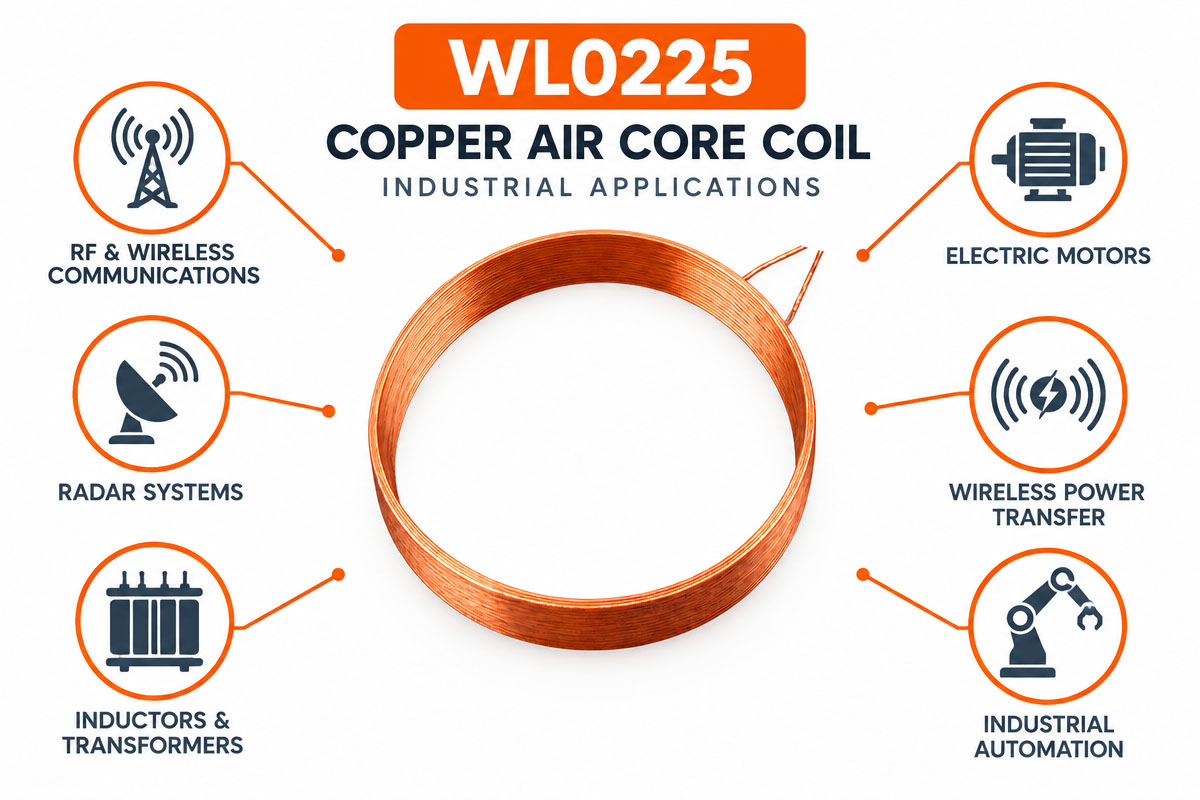
Typical applications are RF communication, wireless systems, antennas, RFID, NFC, sensors, filters, oscillators, impedance matching networks, and special industrial electronics. For OEM projects the coil can be designed to meet the customer’s circuit, installation space, electrical specifications, and production requirements.

High-Frequency Copper Air Core Coil Product Overview

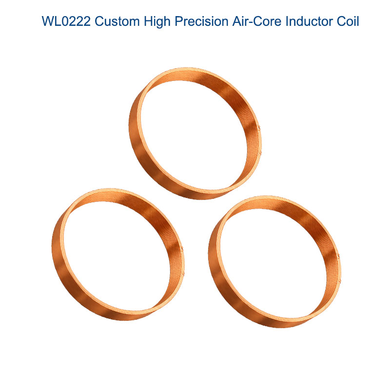
Copper Air Core Coil Flexible inductive component, made of the insulated copper wire wound in a certain shape without a magnetic core. It can be designed in order to optimize inductance, frequency, resistance, current, Q factor, dimensions, and environmental conditions.

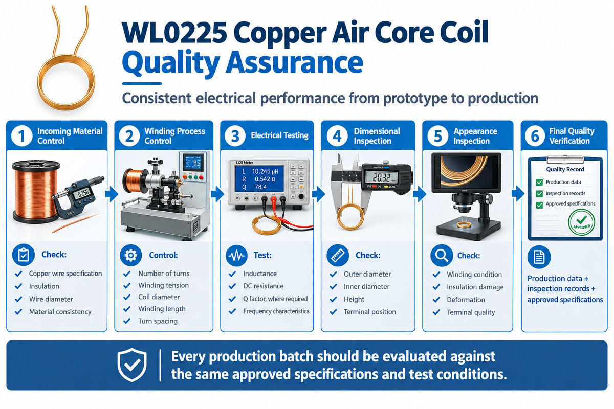
Industrial production includes automatic winding of wire, tension control, forming, terminal preparation, soldering or welding, electrical testing, and dimensional inspection. Depending on the application, manufacturers can provide single-layer, multi-layer, close-wound, or spaced-winding configurations.

For OEM applications, the coil should be designed according to the customer’s electrical specifications, mechanical drawing, installation limitations, and production volume, rather than only selected by appearance and nominal dimensions.

How Does a Copper Air Core Coil Work?

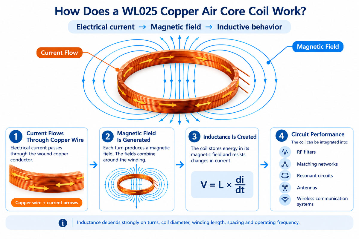
When current passes through the copper coil, a magnetic field is generated around the conductor. In the case of winding of the copper wire into several turns, the interaction of magnetic fields of each turn creates a stronger magnetic field around the coil.

Thus, a coil has inductance and stores energy in the magnetic field of the coil.

The equation that describes the connection between change in voltage and change in current is the following:

V = L * di/dt In which:

V = e.m.f.

L = inductance

di/dt = rate of change of current

As against the air core coil, the magnetic field is not focused by any ferromagnetic material. Therefore, its inductance is very sensitive to its geometry.

Such parameters as:

turns;

diameter of wire;

diameter of the coil;

length of winding;

turning spacing;

working frequency;

resistance of copper;

parasitic capacitance;

quality factor (Q-factor);

installation surroundings

are of great importance.

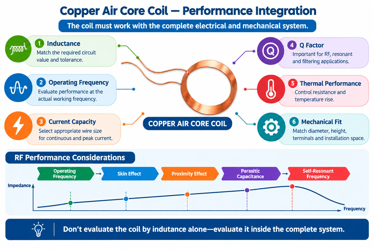
Moreover, at high frequencies, engineers have to consider skin effect, proximity effect, parasitic capacitance, and self-resonant frequency.

Main Features of Copper Air Core Coil

Features of copper air-core coils. Air core coils do not have a core and are highly magnetic and highly conductive electrically. Main features are low hysteresis loss, good high-frequency performance, predictable electromagnetic characteristics, and flexible physical geometry. Engineers can set the wire diameter, turns, winding diameter, winding length, pitch, insulation, and terminal configuration. The air core construction helps to avoid magnetic core saturation and is thus perfect for applications requiring stable magnetic characteristics within a certain range.

Depending on the design, copper air core coils can provide high Q factors, low parasitic magnetic effects, and high repeatability. For OEM production, precision winding machines can guarantee consistent coil dimensions and electrical properties.


High-Frequency Copper Air Core Coil Product Video

High-Frequency Copper Air Core Coil Detailed Display

High-Frequency Copper Air Core Coil Data Sheet

Item Description
SMD Air Inductor Coil Enameled copper wire
Wire Diameter 0.1 (AWG options available)
Winding Type Single-layer round or sectional ย winding
Core Material Air (non-magnetic) copper wire
Footprint length 30-50 mm
Encapsulation Optional varnish, epoxy, or coating
Mounting Through-hole / Custom

Electrical Specifications (Typical)

Parameter Description
Inductance Range 10 ยตH โ€“ 100 ยตH (customizable)
Inductance Tolerance ยฑ2%, ยฑ5%, ยฑ10%
DC Resistance (DCR) Custom
Q Factor High Q, optimized for frequency range
Self-Resonant Frequency High, application-dependent
Operating Frequency kHz to MHz range
Rated Current Custom per design
Insulation Resistance โ‰ฅ10 Mฮฉ

Copper Air Core Coil vs Iron Core Coil: Full Comparison Guide

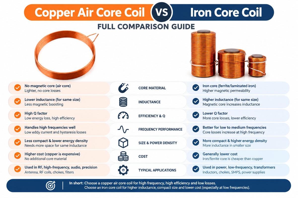
Copper Air Core Coil vs Iron Core Coil Comparison

Both copper air-core coils and iron-core coils are inductive components, but their designs are different, and they also have very different performance. The correct choice depends on frequency, inductance, current, physical dimensions, magnetic requirements, and circuit design.

1. Core Construction

The copper air-core coil is coreless. The magnetic field is mainly through air and surrounding space.

The iron-core coil uses a magnetic core made of iron or other magnetic material. The core increases the effective permeability and allows increasing the inductance of the coil for a specified number of turns.

2. Introduction

The inductance of an air-core coil is mainly defined by coil geometry, such as diameter, length, turns, and spacing.

The iron core coils have the advantage that the core material has higher permeability. Thus, they can get relatively high inductance with fewer turns or smaller physical size.

3. Magnetic Saturation

As there is no ferromagnetic core, the air-core coils are not subject to conventional magnetic-core saturation.

The magnetic flux can become so large that the iron cores saturate. The inductance can drastically change after saturation.

This feature is important in applications where there are high currents or fast-changing magnetic fields.

4. High Frequency Performance

Coreless construction is often preferred for high-frequency applications, as it avoids many of the frequency-dependent losses associated with the magnetic materials.

Hysteresis and eddy-current losses can appear in iron cores. The severity depends on core material, frequency, magnetic flux density, and the design.

Hence, the air core coils are often considered in RF and high-frequency circuits.

5. “Q-Factor”

Well-designed copper air-core coils can have a high Q factor due to the fact that there is no magnetic core, which adds additional magnetic losses.

At high frequencies, however, the Q factor is still limited by the conductor losses, skin effect, proximity effect, and parasitic capacitance.

Q. Iron core coils can have additional core losses, which influence the Q factor.

6. Size of Physical

As the magnetic permeability of the iron core increases, the magnetic inductance of the iron core coils is usually higher in the small volume.

Large inductance can lead to larger dimensions of the air core coils.

However, for many RF applications the required inductance is quite small, which makes an air-core structure feasible.

7. Thermal Properties

In the case of the coil with the air core or iron core, there are Iยฒ * R losses in the copper wire. In addition, iron core designs can lead to core losses.

For high-frequency operation, the designer must consider conductor and core losses where it is applicable.

8. Electromagnetic Properties

As there is no magnetic material to concentrate the flux, the air core coils have larger external magnetic coupling.

This feature can be useful in some antenna and wireless applications but requires careful positioning in order to avoid unwanted electromagnetic coupling.

An iron core concentrates the magnetic flux and therefore has different coupling characteristics.

9. Differences in Application

Copper air core coils are often considered for:

RF circuits

Wireless Communications

Antennas

RFID

NFC

High Frequency Filters

Resonant Circuits

Matching Networks

High Frequency Sensors

Iron core coils are widely used where high inductance, high magnetic coupling, or small magnetic structures are required at the suitable frequencies.

10. Technical Decisions

The choice must not be made solely based on efficiency of the respective design. First, the engineer should determine:

Required inductance

Operating Frequency

Modern-day

Q Factor

Temperature rise

Physical Size/Dimensions

Magnetic coupling

Tolerance

Price

Environmental conditions

Volume of production

The copper air core coil is often preferable when high-frequency characteristics, predictable geometry, and freedom from magnetic core saturation are essential. When high inductance and magnetic concentration are required, an iron core coil may be better.

The best solution for OEM development is the balanced use of both concepts with the real electrical and mechanical requirements of the end product. Prototype testing will verify the inductance, Q factor, resistance, temperature rise, and frequency response.

11. Custom Copper Air Core Coils Buying Guide

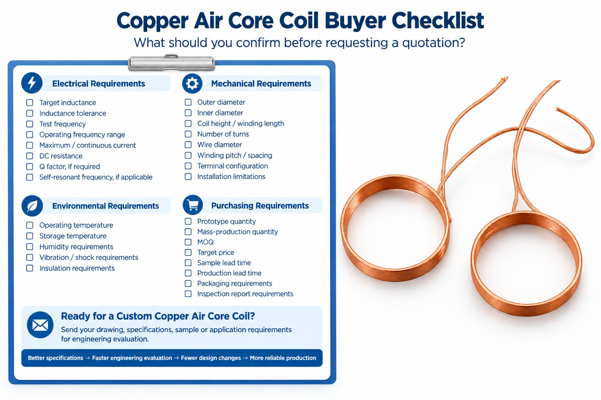
Prior to sending a quotation request, the buyer needs to have:

Desired inductance to be achieved

Tolerance of inductance

How often to test

Range of operating frequency

Maximum Current

DC requirement for resistance

Desired Q factor

Desired Self-Resonant Frequency, where applicable

Diameter of wire

Outer diameter of coil

Inner Diameter of coil

Length of winding

Number of turns

Winding pitch

Configuration of the terminals

Insulation requirements

Operating Temperature

Temperature for storage

Required life

Mechanical drawing 2.2.

Description of application

Quantity per year

Number of prototypes

MOQ for production

Inspection report, mandatory

This will allow the manufacturer to evaluate the coil from the electrical and manufacturing perspectives and will help to reduce the redesign in the development stage.

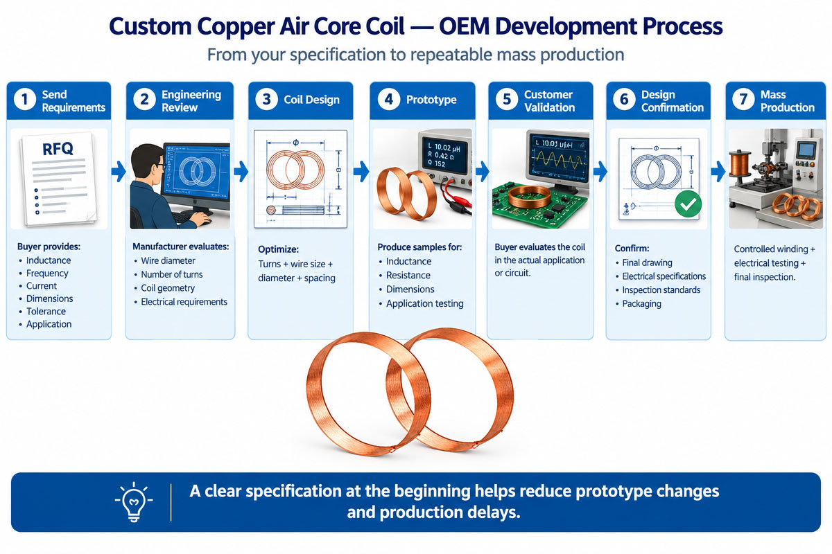
12. Suggested OEM Development Procedure

Step 1 โ€“ Requirements Review

Review of electrical, mechanical, environmental & commercial requirements.

Step 2โ€”Computation of the Coils

Verification of turns, wire diameter, diameter, inductance, resistance, and frequency characteristics of the coil.

Step 3โ€”Designing Engineering

Design of the winding structure and terminal configuration and the mechanical drawing.

Step 4 โ€“ Prototyping

Creation of prototypes for electrical and mechanical verification.

Step 5 โ€“ Application Testing

Testing of the prototype in the real customer circuit or equipment.

Step 6 โ€” Optimization of the Design

Modification of wire diameter, turns, spacing, or dimensions according to the results of testing.

Step 7 โ€” Validation of Production

Verification of tooling, winding process, testing, and quality standards.

Step 8. ย Production in Mass

Ensuring the batch-to-batch consistency with controlled winding and inspection processes.

Step 9โ€”QC

Testing of the inductance, resistance, dimensions, appearance, and other parameters specific to the application.

Step 10 Continuous Improvement

Monitoring of production data and consumer feedback for continuous improvement.

13. Conclusions

A copper air core coil is a flexible inductive component for high-frequency, RF, wireless, and industrial electronic applications. Its coreless design allows avoiding the common magnetic core saturation and can provide good high-frequency characteristics if the coil is designed properly.

However, making a good coil is more complicated than just selecting copper wire and specifying inductance value. Wire diameter, turns, coil geometry, frequency, current, Q factor, parasitic capacitance, thermal characteristics, and mechanical tolerances should all be taken into account.

Customer-specific copper air core coils must be designed for OEM application according to the full electrical and mechanical requirements of the customer’s system. A prototype test and a controlled mass production process in early engineering collaboration can help to ensure stable characteristics and repeatability.

High-Frequency Copper Air Core Coil E;electronics Application

Custom Copper Air Core Coil Industrial Application

Predictable inductance, good high-frequency performance, and lack of magnetic-core loss make copper air-core coils widely used in electronic and industrial systems.

RF & Wireless Communication

In RF circuits, air-core coils are used in tuning circuits, oscillators, filters, and impedance matching networks. As there is no core in the coil, it operates perfectly at high frequencies without saturation characteristics of magnetic cores.

Antenna Systems

Antennas for transmitting, receiving, and tuning include copper air-core windings. The geometry of the coil can be customized depending on the frequency and installation space.

RFID and NFC

RFID and NFC systems often require electromagnetic coupling through precisely controlled coils. Coil dimensions, number of turns, and resistance directly influence system efficiency.

Sensors

Inductive sensors use air-core coils to detect position, motion, metallic objects, or changes in electrical characteristics.

Power Electronics

High-frequency power circuits can employ air-core inductors to control the current and energy without causing magnetic-core saturation.

Filters and Matching Networks

LC filters, impedance matching circuits, and frequency selective networks use copper air-core coils.

Industrial Electronics

They can be customized for test equipment, communication modules, measurement equipment, control systems, and specialized OEM electronic assemblies.

ย Reasons Why Copper Air Core Coils Are Popular in Wireless Communication Systems

Modern RF systems often operate at frequencies where magnetic-core properties can lead to losses, saturation, or non-linearity. Copper air-core coils are popular for wireless communication.

The absence of core makes it possible to define the electromagnetic properties of the coil mostly by its geometry and conductor. It gives engineers a lot of flexibility in designing RF matching circuits, filters, resonant circuits, antennas, and coupling structures.

Copper has a high conductivity, which can help to reduce losses in the conductors. However, for the high-frequency applications, the designer must take into account the skin effect and proximity effect, as the AC resistance can be very different from the DC resistance.

The wireless applications often require small physical size and strict electrical specifications. A copper air core coil can be customized by optimization of wire diameter, number of turns, diameter of the coil, winding pitch, and spacing.

The repeatability is another great advantage of the coil. Using the automatic winding machines and controlled inspection, the manufacturer can make the coils with uniform geometry and electrical characteristics.

Therefore, copper air core construction is often considered for:

RF comms modules

Systems for wireless charging

RFID devices

Near Field Communication Devices

Antenna circuits

RF filters

Oscillators

Matching impedance circuits

Sensor systems

Electronic equipment, high frequency

For OEM applications, the coil must be designed as a part of the RF circuit as a whole, not as a separate element.


High-Frequency Copper Air Core Coil Advantage and Disadvantage

Custom Copper air core coil advantages and disadvantages

High-Frequency Copper Air Core Coil Advantages

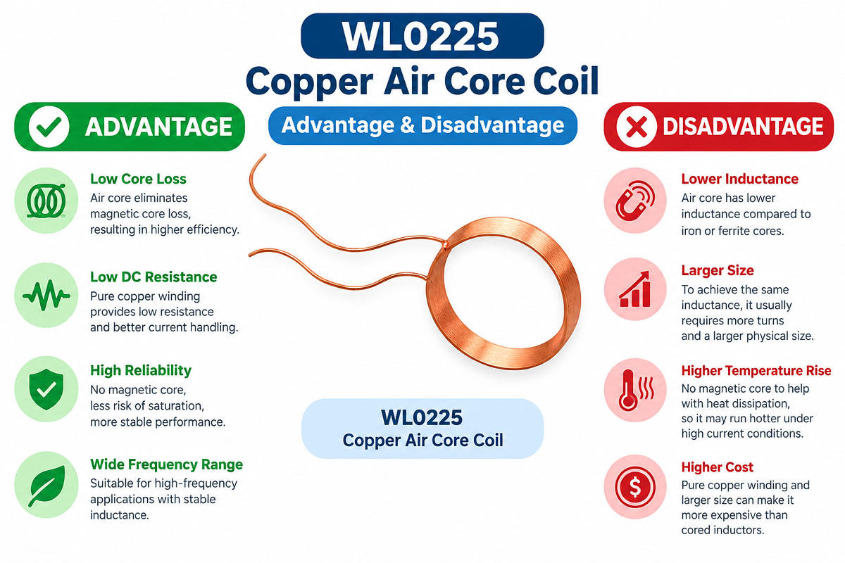
There are some advantages that make the copper air-core coils more preferable for industrial electronic applications. As there is no magnetic core, there are no core saturation or dependency on the magnetic material properties. These properties make the copper air core coils particularly advantageous for high-frequency circuits.

Copper has a high conductivity, which will help to reduce the resistance of the conductor. The winding geometry is highly customizable, providing engineers with the possibility to tune inductance, Q factor, current rating, and geometrical dimensions.

Another advantage is the flexibility. There are many kinds of copper air core coils in different diameters, winding lengths, turn numbers, and configurations. They can be used for RF circuits, antennas, filters, wireless systems, and other kinds of electronic assemblies.

High-Frequency Copper Air Core Coil Disadvantages

The main drawback of Copper Air Core Coils is that the inductance of such coils is normally less than that of coils with high-permeability magnetic cores of equal physical volume. The inductance of air-core coils can also be more dependent on the coil geometry and surrounding material.

The current, passing through the winding, causes heating by the copper resistance. The skin effect and proximity effect can cause the increased AC resistance of the coil at high frequencies.

There is no magnetic core, so the magnetic field of the coil is not concentrated, and it can also generate or receive electromagnetic interference.

Hence, copper air core coils have the following good advantages: high frequency and customization, but physical size, thermal characteristics, electromagnetic coupling, and high-frequency parasitic effects must also be taken into account during the design.

Copper Air Core Coil Troubleshooting Guide

Custom Copper Air Core Coil Troubleshooting Guide

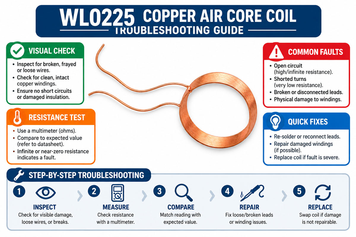
Problem 1: Absence of Inductance

The reasons are too few turns, too large a diameter of the coil, wrong winding length, or dimensional deviations. First of all, it is necessary to calculate the turns and measure the physical dimensions.

Problem 2: Too Much Inductance

Too many turns, a small diameter of winding, or improper spacing can increase the inductance. It is necessary to compare the geometry of the winding with approved drawings.

Problem 3: Too Much Resistance

It is necessary to check wire diameter, wire length, solder joints, and terminal connections. The smaller conductor or longer winding can lead to higher resistance.

Problem 4: Heating

It is necessary to check the current, resistance, cooling, and wire size, which can lead to overheating. DC & AC loss must be checked.

Problem 5: Bad RF Characteristics

It is necessary to examine the Q factor, parasitic capacitance, self-resonant frequency, winding spacing, and effects of installation. The frequency of measurement must be appropriate to the application.

Problem 6: Different inductance from one batch to another

It is necessary to check winding tension, coil diameter, turn spacing, wire specifications, and measuring equipment. Automated winding and controlled inspection can help to increase the repeatability.

Problem 7: Deformation

It is necessary to check the forming fixture, packing, and handling methods of preservation of coil geometry during transportation and assembly.

Problem 8: Misoperation of the Circuit

It is necessary to check the influence of nearby metal parts, PCB traces, or other magnetic and electromagnetic parts on the coil. Copper air core coils are highly sensitive to electromagnetic conditions of the environment.

The systematic failure analysis should include the comparison of the failed coil with a qualified reference sample and electrical, dimensional, and environmental tests.

High-Frequency Copper Air Core Coil FAQs

1. How to Select the Right Copper Air Core Coil for My Application?

Required inductance, operating frequency, current, resistance, Q factor, physical size, tolerance, and operating temperature. Parasitic capacitance, self-resonant frequency, skin effect, and proximity effect should also be considered for RF applications. One can also send their circuit requirements or mechanical drawing to the manufacturer for calculation of the right wire diameter, number of turns, coil diameter, and winding configuration.

2. Can you manufacture me a Copper Air Core Coil according to my requirements?

Yes. Copper air core coils can be custom designed for inductance, wire diameter, turns, coil diameter, winding length, turn spacing, terminal configuration, insulation, and mechanical dimensions. OEM manufacturers can make prototypes from customer drawings or requirements prior to mass production.

3. What information should I provide for a quotation?

The buyer must specify the desired inductance and tolerance, operating frequency, maximum current, DC resistance, Q factor, if required, dimensions of the coil, wire requirements, terminals configuration, operating temperature, yearly quantity, prototype quantity, and delivery requirements. A mechanical drawing or existing sample is helpful for accurate quotation and engineering.

4. Can Copper Air Core Coils be used in high frequency applications?

Yes. They are widely used in RF and high-frequency circuits, as they do not have a magnetic core and, therefore, cannot saturate and have magnetic losses. However, the high-frequency design should take into account skin effect, proximity effect, parasitic capacitance, and self-resonant frequency. It is necessary to test the coil at its actual operating frequency.

5. What affects the inductance of Copper Air Core Coil?

The inductance depends mostly on the number of turns, the diameter of the coil, the winding length, the turn spacing, and the general geometry of the coil. The presence of nearby magnetic or conductive material can also influence the inductance. Therefore, if the tight tolerance of inductance is required, care should be taken of mechanical tolerances.

6. How can I ensure the consistency of each production batch?

Specify electrical and mechanical acceptance criteria before mass production. These should include inductance tolerance, test frequency, DC resistance, dimensions, wire specification, appearance, and terminal requirements. It is also necessary to verify the winding process, testing equipment, and production control of the manufacturer.

7. What is the lead time for a custom Copper Air Core Coil?

The lead time depends on the complexity of the coil, the requirement for the tooling or fixtures, the quantity of prototypes, the material availability, the requirements for testing, and the quantity for production. The simple prototypes can be manufactured relatively fast, while customized coils requiring new tooling, special winding processes, or validation can take longer to develop. The buyer is recommended to verify lead times of the prototypes and mass production before ordering.

8. How can I optimize the cost of a custom Copper Air Core Coil?

The cost is often optimized through optimization of wire diameter, turns, winding process, terminal configuration, tolerances, packaging, and quantity for production. Special materials and tight tolerances should be avoided unless the application requires it. Accurate specifications at the initial stage of the project will help to reduce engineering changes, prototypes, and production rework.

ย How to Select a Copper Air Core Coil

Selection of the appropriate copper air core coil is more than matching a nominal inductance value. One has to take into account the integrated electrical, mechanical, thermal, and manufacturing requirements.

1. Required Inductance Definition

One should start with required inductance and tolerance. For instance, the application requires 10 ยตH ยฑ 5%. Required tolerance should be confirmed under actual operating frequency and test condition.

2. Operating Frequency

Frequency is an influential factor for the coil’s performance. Due to the skin effect, proximity effect, and parasitic capacitance, a coil designed for low-frequency operation may not perform the same way at RF frequencies.

3. Wire Diameter Selection

Wire diameter determines the resistance, current-carrying capacity, thermal performance, and physical size. A thicker wire usually provides lower DC resistance but occupies more space during winding.

4. Number of Turns

More turns increase inductance, wire length, resistance, and parasitic capacitance. The optimal number of turns should be calculated but not selected arbitrarily.

5. Coil Dimensions Verification

Outer diameter, inner diameter, length of winding, height, and terminal position. Mechanical tolerances should be marked on the drawing.

6. Existing Conditions Analysis

The maximum peak and continuous current have to be indicated. The manufacturer has to evaluate copper loss and temperature rise at the anticipated operating condition.

7. Q Factor Review

In some cases, the Q factor can be a crucial parameter for RF applications. For resonant and filtering applications, a higher Q factor is desirable. The required Q factor depends on the circuit.

8. Self-Resonant Frequency Verification

All coils have parasitic capacitances. Operating frequency has to be different from the coil’s self-resonant frequency.

9. Environmental Factors

Materials and construction should be chosen depending on temperature, humidity, vibration, insulation requirements, and installation conditions.

10. Production Necessities

For OEM projects, before the design is finalized, one should verify the quantity, tolerance, inspection method, packaging, lead configuration, and repeatability.

How to Avoid the Common Design Mistakes

Design mistakes can negatively affect the performance or manufacturability of a copper air core coil.

Mistake #1: Inductance Only Specification

Inductance alone is not sufficient. One has to define the frequency, current, resistance, Q factor, and tolerance.

Error 2: No Attention to Operating Frequency

A coil meeting inductance specification at one frequency may not meet it at another frequency.

Mistake 3: Wire That Is Too Thin

Thin wire can increase the resistance and temperature rise, especially in the case of continuous current.

Mistake #4: No Attention to Self-Resonance

At high frequencies parasitic capacitance can significantly influence the coil.

Error 5 โ€“ Excessive Winding Density

Too tight winding can cause increased parasitic capacitance and proximity effects. Winding configuration should be chosen based on the application.

Mistake 6: Bad Mechanical Tolerances

Even small changes in diameter, spacing, and length of winding will change the inductance. Thus, tolerance specifications are necessary for critical dimensions.

Mistake 7: Overlooking of Thermal Conditions

Electrical performance should be verified at the real operation temperature, but not only at the room temperature.

Error 8: Design Without Manufacturing Inputs

Theoretical design may not be economically reasonable and stable for mass production. Early communication with the coil manufacturer can help to avoid redesign.

Error 9: Poor Testing Specifications

The drawing should specify the test frequency, method of measurement, tolerance, and acceptance criteria.

Error 10: Selection of the Coil by Size Only

Coils having similar dimensions can have quite different electrical characteristics depending on wire size, the number of turns, spacing, and construction.
 

Get A Free Quote Now

Contact Form

Related Products

Related News

Scroll to Top

Get A Free Quote Now !

Contact Form
If you have any questions, please do not hesitate to contact us.
Weilong Solenoid Company Culture