Air Core Coil: Complete Non-Magnetic Inductor Guide


Chapter 1: What is an air core coil?
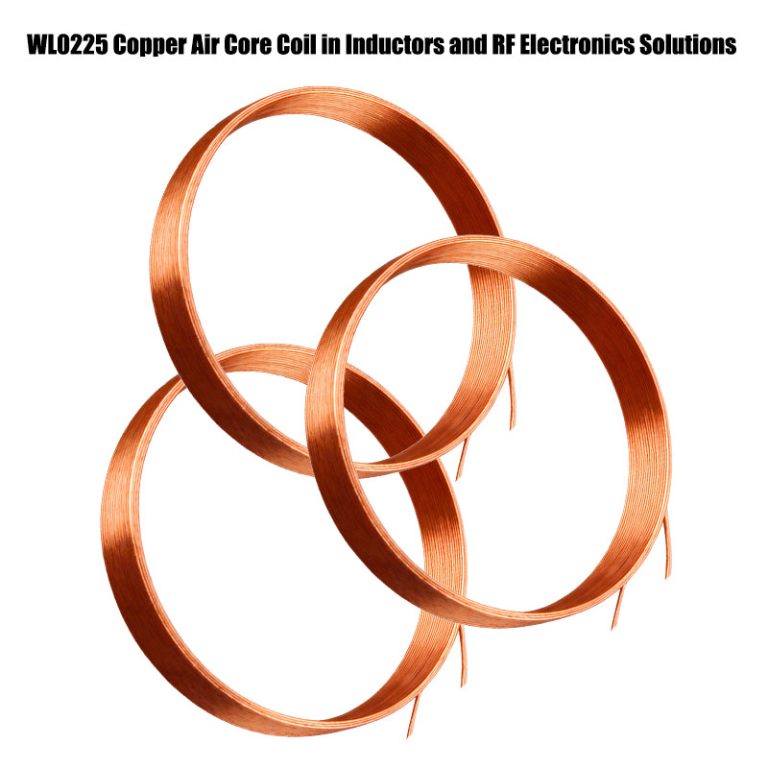
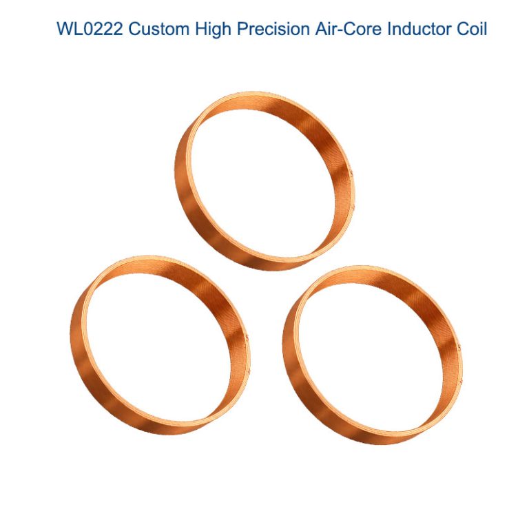
An air-core coil inductor has its winding wound around a non-magnetic core, such as air or a non-ferrous substance. This differentiates it from iron or ferrite-core inductors. In an air-core coil inductor, there are no magnetic materials in its core. This inductor works solely because of the self-inductance provided by its wound wires. Air-core coil inductors are used in applications in which high accuracy and linearity are required.
Chapter 2: Operating Principle
Air core coils rely on basic electromagnetic phenomena in the absence of magnetic core interactions between the coil and current paths, such as
Figure: Deepak
Self-inductance is denoted by the symbol L. As the alternating current passes through the coil, a varying magnetic field is produced around the coil. As a result, the back-electromotive force is created in opposition to the flow of the current.
Impedance (Z)
At frequency , the coil impedance expression becomes
Z = 2πfL
where L is theQ Factor (Quality Factor): It has been defined as Q = (ωL)/R, where R is the resistance of the coil.
Important Attributes:
No Core Saturation: If there is no core material, the value of the inductance does not change with
Linear B-H Relationship: Proportionality between magnetic flux density (B) and magnetic field strength (H) such that B
- Température stability: Variations faibles dans la tempér
Frequency independence: There are no core losses dependent on the frequency.
Chapter 3 : Structure and Construction
3.1 Core Components:
Wire: Copper (bare/enameled), Litz wire, silver-plated copper, or aluminum
Winding Form: Self-supporting, plastic former, ceramic, or fiberglass bobbin
Support Structure: Epoxy coating, varnish impregnation, or mechanical framework
Terminations: Solderable leads, PCB pins, or surface mount terminations
3.2 Common Geometries:
Solenoid/Wound Coil: Cylindrical helix winding (most common)
Flat Spiral: Planar spiral for PCB integration
Toroidal: Doughnut-shaped with uniform containment of magnetic field
Basket/Spider Web: Open construction for minimal capacitance
Variable Air Core: Adjustable with movable tap or sliding contact
Construction Techniques:
Machine Winding: Precision winding for reproducibility of parameters
Hand Winding: For prototypes or custom values
Litz Wire Construction: Several insulated strands in parallel to reduce skin effect
Self-Supporting: Rigid wire (copper tubing) holds shape sans former
Chapter 4: Air Core Coil Datasheet
Coil Type: Solenoid / Toroid / Planar / Helical Inductance (L): 0.1 μH – 10 mH (depends on model) Rated Current: 0.1 – 5 A Operating Frequency: 10 kHz – 1 GHz Wire Material: Copper / Silver-plated copper Coil Form Material: Plastic, Ceramic, Epoxy DC Resistance (Rdc): 0.01 – 10 Ω Temperature Range: -40°C to 125°C Mounting Type: Through-hole / Surface-mount Application: RF circuits, wireless charging, antennas, electronics
Chapter 5 ; Different types of coils with air cores
Based on their shape, winding style, and use, there are different kinds of air core coils, which are also called non-magnetic inductors. Each type has its own advantages for different systems and circuits.
1. Air Core Coil for Solenoids
Shape: A cylinder with wire winding around it.
Some features are:
Easy to make and not too hard
Gives a straight magnetic field along the axis
For RF circuits, small inductors, sensors, and electronics that need to be very accurate.
2. A Toroid with an Air Core Coil
Shape: A winding that looks like a donut.
Features:
There is very little electromagnetic interference (EMI).
Keeps the magnetic field inside the core.
Low stray field and high efficiency
Uses: RF transformers, circuits that work at high frequencies, and fragile electronic devices.
3. Planar Air Core Coil
Shape: A flat spiral coil, which is common on a PCB or substrate.
Features:
Small and not very noticeable
Can be used in circuit boards
Works well to transfer power wirelessly
Uses: IoT electronics, RF devices, PCB inductors, and wireless charging.
4. A coil with a helical air core
Shape: a winding that is open and spiral or helical.
Characteristics:
You can change the coil’s diameter or spacing to change the inductance.
How well it works at high frequencies
Uses include antennas, RF tuning circuits, oscillators, and signal conditioning.
5. Coil with many layers of air core
Shape: A lot of layers of wire winding on top of each other to make the inductance higher.
Features:
Adds inductance without making the coil bigger.
Can handle a fair amount of current
Uses: RF circuits, matching impedances, and electronics that need to be very precise.
6. Air core coil that is printed or built in
Shape: The conductive traces on the PCB are printed in a spiral or toroidal shape.
Characteristics:
Very small and light
Great for automated production
Not enough capacity right now
Uses: wireless charging pads, sensors, and small electronics.
the type of air core coil Summary:
Solenoid: Easy to use, straight, and at low frequencies
Toroidal: High efficiency, low EMI
Planar: small, integrated into the PCB, and charges wirelessly
Helical: adjustable and RF-tunable
Multi-Layer: More inductance and a moderate amount of current
Printed: Small, lightweight applications based on PCBs
Chapter 6: Advantages and Disadvantages
Advantages
High Linearity: No saturation of the core means linear values of inductance regardless of the current flow
Excellent High-Frequency Performance: Functions properly at GHz frequencies without any core losses
Low Distortion: Harmonic and Inter-modulation Distortion that is
Temperature Stability: Usually ±50 ppm/°C compared to ±200 – 500 ppm/°
Loss Without Hysteresis Cycles: Reduces energy loss caused by reorientation of
Non-Eddy Current Loss: Without conductive core material
Clos
Predictable Behavior: Parameters calculable with high accuracy from physical size
Lightweight: Much lighter than equivalent iron-core inductors
Disadvantage
Lower Inductance Density: It takes more turns/volume for a given inductance compared with magnetic
Large Size: For Similar Values of Inductance
Magnetic Field Radiation: Uncontained fields will interfere/crosstalk
Less Q at Low Frequencies:
Resistance Takes Over Due to Increased Wire Usage
The reason for a
Mechanical Fragility
Typically must have additional support or potting material
Cost: The more copper/wire that is used for a given inductance
Tuning Sensitivity: Susceptible to hand capacitance effects in RF circuits
Chapter 7: Applications of air core coil
Radio Frequency Circuits:
Tank Circuits: LC oscillators and resonant circuits in transmitters/receivers
RF Chokes: Blocking RF while passing DC in amplifier circuits
Antenna Systems : Loading coils, impedance matching networks
Filter Networks: Bandpass, low-pass, and notch filters
Test & Measurement:
Standard Inductors: Precision reference inductors for calibration
Current Sensing: Rogowski coils for AC current measurement
Probes: Magnetic field sensing and near-field probes
High Fidelity Audio:
Crossover Networks: Loudspeaker crossovers requiring linear phase response
Tube Amplifiers: The role of high voltage chokes in vacuum tube circuits
Scientific & Medical:
MRI Systems: Gradient coils and RF coils
Laboratory Equipment: NMR probes, magnetic field generation
Particle Physics: Detector coils and magnetic field sensors
Power & Industrial:
Snubber Circuits: Suppression of high-frequency switchings
Resonant Converters: LLC and other resonant power supplies
Power Factor Correction: High-current line frequency applications
Specialised Applications:
Tesla Coils: High-voltage resonant transformers
Metal Detectors: Search coils and discrimination circuits
Wireless Power: Transmitter and receiver coils
Chapter 8 : Why Air Core Coils Are Becoming More Popular
Air core coils, or non-magnetic inductors, are gaining popularity in electronic circuits, radio frequency circuits, wireless charging systems, etc., due to a few advantages offered by these coils over others:
- No Magnetic Saturation
Air core coils don’t suffer from saturation at higher currents like iron core coils or ferrite core coils.
The inductance remains constant in these coils even when the current changes in the circuit.
Suitable for circuits where consistency is required in operation.
- Air Core Coils Perform at High Frequencies
Air core coils have low core losses, making them suitable for radio frequency circuits, antennas, etc., where wireless communication is required.
Air core coils can operate at higher frequencies compared to magnetic core inductors.
- Air Core Coils Are Small in Size and Light in Weight
The coils require a smaller amount of space because no core is required in these coils.
The coils are lighter in weight because no core is used in these coils.
The smaller size makes them easier to integrate with printed circuit boards.
- Less Magnetic Interference
Air core coils don’t have a core in them, so they don’t interfere with other components in a circuit because no stray magnetic fields are generated by these coils.
These coils can be used in space because no interference is generated by these coils.
- Oscillators, Filters, Tuners, etc.
Oscillators, filters, tuners, etc., make use of air core coils.
They provide a linear inductance that is predictable and linear, which is very important when it comes to devices that need to be very accurate.
- Good for the Environment and Long-Lasting
They are good for the environment since they do not contain ferrite and iron cores, which means they do not contain heavy metals.
Also, they do not break easily since they do not contain magnetic cores that can overheat.
Chapter 9 : How to Pick the Best Air Core Coil
It is very important that you pick the best air core coil that will not only work best but also perform its functions with the highest accuracy and last as long as you want it to last. Here’s how you can pick the best coil that suits your needs:
1. Determine the Operating Frequency
For the best results, air core coils can be used when the frequency is high, i.e., kHz and GHz.
To ensure that your coil works best and with minimal losses, you need to pick the best coil that is suitable for the desired frequency.
For example, you can consider using it with RF circuits, antennas, and wireless chargers that work with MHz and GHz.
2. Determine the Inductance You Need
To ensure that your coil works best, you need to determine the required inductance that your circuit can handle.
The inductance is determined by the following parameters:
N is the number of turns.
D is the diameter.
Length of the coil (l)
3.Pick the Right Kind of Coil
Solenoid coils are cylindrical in form and are suitable for use in small circuits.
Toroidal coils are very resistant to EMI, making them suitable for use in applications where EMI is a concern.
Planar coils are flat in form and are suitable for use in PCB designs, wireless charging, and other small applications.
Helical coils are open spiral coils, often used in antennas.
4. Material and Gauge of the Wire
Copper is the standard, but better results can be achieved with silver-coated copper.
Higher gauges are better because, in this case, bigger is better.
5. Weather Considerations
The range of temperature in which it can be used must be taken into consideration.
6. Mounting and Shape Considerations
The mounting style must be chosen: Through-hole, Surface Mount, or Planar.
The coil must be able to fit in the space allocated in the PCB or device design.
7. Feedback or Tuning Requirements
Some applications may require inductance that can be tuned.
Coils must be chosen with a tolerance that does not change much with temperature.
8. Consider the Data Sheets from the Manufacturer
For any coil, the following must be checked:
Inductance
Resistance in DC
Maximum current
Range of frequency
Mounting and size requirements
Fixing problems with air core coils
Air core coils are normally reliable since they are simple and lack any magnet. However, issues may arise when these coils are used for high-frequency, RF, or wireless charging applications. Here are some ways to troubleshoot common issues:
Chapter 10 : Troubleshooting of air core coil Not Within Specifications
1. Symptoms: The circuit does not tune well, signal frequency is shifting, and efficiency is low.
What Could Be Going On:
The number of turns is incorrect
The length or diameter of the coil was modified
The spacing between wires is uneven
Answer:
Use an LCR meter to measure inductance and compare it to the data sheet
Change or rewind the coil
- Getting Too Hot
Symptoms: The coil gets too hot, performance is poor, and it may destroy the insulation
What Could Be Going On:
Too much current for its rated capacity
Lack of proper ventilation or heat dissipation
Answer:
Reduce duty cycle or current
Ensure proper air circulation around the coil
If it persists, use thicker wire or insulation
- Open Circuit or Broken Coil
Symptoms: The circuit does not work at all, and no current flows
What Could Be Going On:
Bad solder joints or broken wire
Broken coil from stress or vibration
Answer:
Check for bad solder joints or broken wire
Change or repair the coil if it is broken
- Interference from Electromagnetic Fields (EMI)
Symptoms: Distortion of the circuit, noise in signal wires, and instability of RF
Some possible causes are:
Materials are conductive or magnetic
Exposed coil in sensitive electronics
Answer:
Remove the coil from items that could cause interference.
Use ferrite beads and electromagnetic shielding.
To reduce the number of stray fields, the coil can be toroidal or planar.
- RF Circuits that Change Signals
Signs: bad tuning, frequency drift, and low Q factor.
Possible Reasons:
Poor coil shape
Alterations in the distance between the coil turns and the number of coil turns
Proximity to metals and other inductive devices
Answer:
Verify and keep the coil geometry the same.
Verify that you are at the correct distance from metals.
If there is still distortion, change the coil.
- Damage to the Body
Signs: cracked coil form, bent wire, and damage to the wire’s insulation.
Possible Reasons:
Stress due to machines, being dropped, and heat
Answer:
Check the coil form with your eyes.
Replace the coils.
Consider using ceramics and epoxy resin as coil forms.
Chapter 11: Conclusion
Air core coils are the closest one can get to an ideal inductor, and they are linear and high-frequency whenever a magnetic core becomes an obstacle. Though they lack the compactness of a ferrite or an iron-core coil, they are accurate and stable enough to be indispensable.
Design & Selection Guidelines:
Frequency Range: Preferred use: above 1 MHz; magnetic cores: below 100 kHz
Linearity requirements: Necessary for standard measurements as well as low distortion circuits
Size Constraints: Should accept larger volume for better performance characteristics
Interference Management: Use of shielding or physical barriers in dense sub-systems
Optimization of the Q factor. Litz wire for frequencies up to several MHz; larger diameters for lower frequencies.
Future Directions:
3D-Printed Formers
Custom geometries for optimized magnetic field distribution
Advanced Wire Materials: Higher Conductivity Composites and Superconductors
Integration Technologies: Embedded air-core structures in multilayer PCBs
Automated Optimization: AI-based winding designs for particular performance characteristics
Nano-fabrication: Micro-scale air core coils for integrated circuits
Chapter 12 : Technical References
Inductance Range Typical Uses:
1 nH – 100 nH: Ultra high frequency circuits above 500 MHz, impedance matching
100 nH – 10 µH: VHF/UHF circuits (30-500 MHz
10 µH – 1 mH:
HF circuits (1-30 MHz), filters, audio
1mH ~ 100mH : Applications in low-frequency, power, or measurement standards
- C. (Altern
RF Small Coils (1-100 nH): Q = 50-150 at 100
Medium RF Coils (1-10 µH): Q=100-300 @
Litz Wire Coils: Q = 200-500 at 1 MHz
Large Power Coils: Q = 20-100 at lower frequencies
*Wire Selection Guide:*
<1 MHz: Solid round wire (Cost-effective)
1-10 MHz: Litz wire or large diameter solid wire
> 10 MHz: Silver-plated wire or tubing – skin effect predominant.
High Current: Rectangular/square wires or tubing for increased packing
Common Standards:
Military: MIL-
Commercial: IEC 60182,
Test Methods: IEC 62024, ASTM
Design Note:
The self-resonant frequency (SRF) of an air-core coil is where the capacitance between the turns resonates with the inductance. Always operate below the SRF (about 80% of SRF).
For precision applications, one must consider controlled environment winding, such as temperature and humidity, and post-winding stabilization, which entails thermal cycling.
FAQ of Air Core Coil
A: Air core coils eliminate core saturation, hysteretic losses, and issues with permeability vs. temperature-frequency. These coils are needed for applications in which linearity, high Q at high frequencies, or predictable temperatures are important.
A: For single layer solenoid, *L (µH) = \(\dfrac{d² × n²}{18d+40l}\)*, whereas d is diameter in inches, n is number of turns, and l is length in inches
A: Yes, within the limits of wire gauge and cooling. Core saturation current does not affect inductance—at all, compared to magnetic cores. For high current, a wide-diameter wire or a copper tube.
A: Litz wire is made up of many strands that are separately insulated to lower skin effect power dissipation at radio frequencies [typically 50 kHz to 2 MHz]. Used for high Q designs at such frequencies.
A: Electrostatic shielding (Faraday shield) using a non-magnetic conductive material (copper or aluminum) and a gap to prevent eddy currents. Magnetic shielding is hard and mostly accomplished by distance and orientation.
A: These designs reduce inter-winding capacitances that tend to produce self-resonance at lower frequencies. This enhances the operational frequency range and maximizes values of Q.
A: Minimal direct effect (only expansion coefficients affect dimensions). Temperature expansion coefficients are +50 ppm/°C (0.005%/°C), while ferrites are 200-800 ppm/°C. The resistance of copper rises with temperature (0.4
A: Yes. As flat spiral coils or as miniature wound elements with non-magnetic ceramic or plastic formers. Such coils possess the features of air-core coils but in a much smaller or packaged form.