Introduction to Push-Pull Linear Solenoid vs. Pull Solenoid
Electromagnetic solenoids are used in industry, automotive systems, medical equipment, electronic locks, and many other areas of mechanical control.
They convert electrical energy into mechanical energy, thus allowing the machine to do work like open valves, unlock locks, move elements, and switch.
There are two popular types of actuators among those that perform linear movements—pull solenoids and push-pull linear solenoids.
Both operate on the principle of electromagnetic interaction, but the mechanical design, directions of movement, and requirements of the application can differ.
When energized, a pull solenoid is typically designed to pull a moveable plunger into the solenoid coil or magnetic housing. A push-pull linear solenoid allows the generation of pushing and pulling movement according to mechanical requirements.
It is critical to know the difference between the two solenoids in order to choose an appropriate actuator for your OEM project. Otherwise, the wrong choice of solenoid can lead to insufficient force generation, wrong direction of movement, complicated installation, or high power consumption.
In this article we will explore the difference between two types of actuators, how they work, their advantages and disadvantages, and selection criteria.
1. What Is a Pull Solenoid?
A pull solenoid is an electromagnetic actuator that, when energized by its coil, produces a pulling motion.
It operates on the principle of electromagnetic attraction. The current flowing through the coil creates a magnetic field. The magnetic field attracts a moveable ferromagnetic plunger toward the powered magnetic pole.
The structure of a conventional pull solenoid includes:
Copper coil: the magnetic field is created due to the current passing through the winding.
Movable plunger: a ferromagnetic metal part that moves towards the magnetic housing.
Magnetic housing: assists in focusing magnetic flux and creates a magnetic return path.
Return spring: returns the plunger to its initial position after removing power.
Bobbin: provides support to the coil winding and electrical insulation.
Electrical connections: connect the coil to the power supply.
1.1 How Pull Solenoid Works?
The process of its operation is fairly simple.
First, DC voltage is applied to the coil, causing the current to flow through the copper winding.
Second, the coil creates a magnetic field attracting the moveable plunger.
Third, the plunger moves towards the magnetic pole, creating mechanical pulling motion.
Finally, after turning off power, the plunger returns to its initial position under the action of the return spring.
Such a design is quite typical and is known as a spring-return pull-type solenoid.
1.2 Typical Applications of Pull Solenoids
The most popular uses of pull solenoids include:
Electronic locks on doors.
Mechanical release mechanisms.
Automotive locking systems.
Industrial switches.
Valves controlling systems.
Vending Machines.
Automatic dispensing apparatus.
Because of its relatively simple design, it is used in cases when only a simple pulling motion is required.
2. What Is a Push-Pull Type Linear Solenoid?
Push-Pull Linear Solenoid: An electromagnetic actuator that is designed to produce linear mechanical displacement in a push or pull direction or both depending on the actuator design.
A push-pull design, opposite to the conventional pull solenoid that primarily creates inward pulling motion, can be designed to create an outward pushing motion or other motion functions depending on the application.
A typical push-pull linear solenoid includes:
Electromagnetic coil: generating a magnetic field.
Plunger assembly: translates electromagnetic force into mechanical motion.
Magnetic housing: forms a part of the magnetic path.
Return spring or mechanical return system: gives the return motion.
Bobbin: holds the copper winding.
Mounting structure: allows installing the actuator in the client’s equipment.
2.1 Working Principle of Push-Pull Linear Solenoid
It depends on the magnetic and mechanical design of the solenoid.
Typically, with spring return, energizing the coil pulls the plunger toward the magnetic pole. The motion can be created to provide a pulling or pushing force at the point of connection.
For example, a link or shaft design can transduce the inward movement of the plunger into outward pushing.
Other designs can use other magnetic constructions for two-powered movement directions.
It is crucial to understand that a standard single coil solenoid does not inherently create a powered force in any direction. The exact working principle has to be defined by the internal design and return mechanism.
Properly engineered push-pull linear solenoids can be customized for specific force, stroke, voltage, and installation requirements.
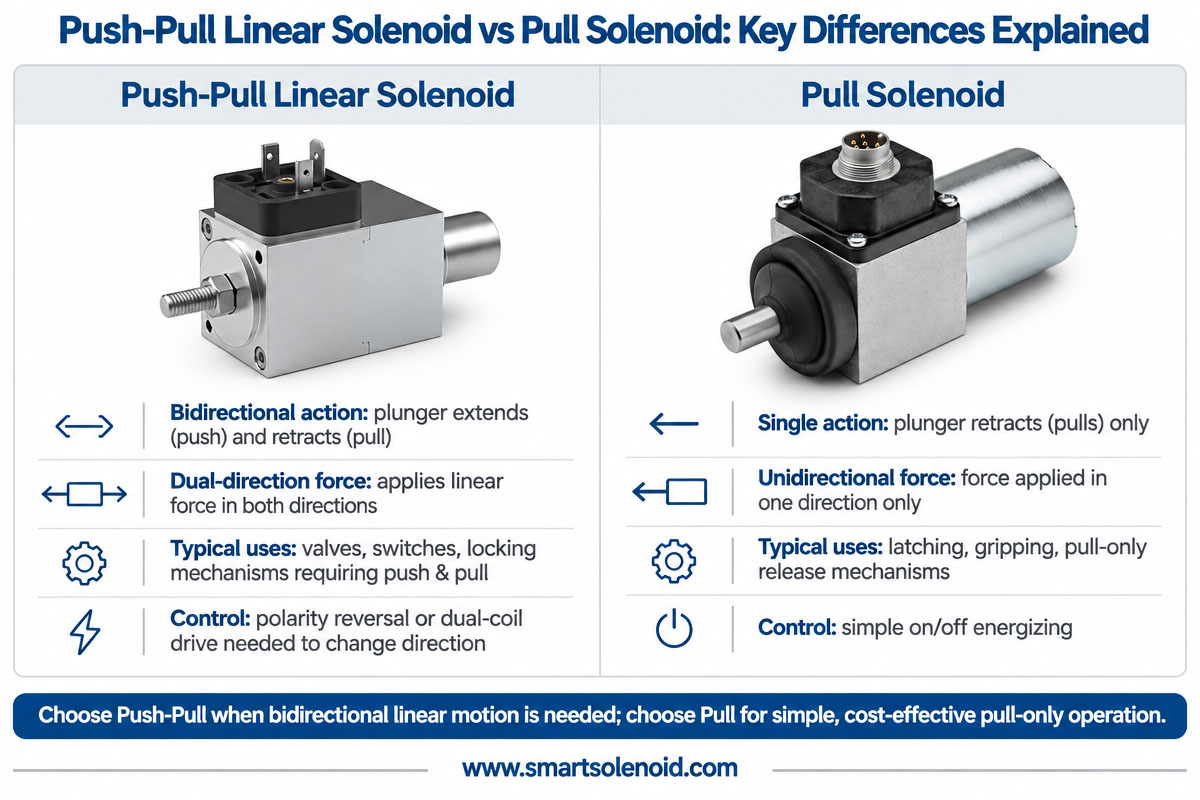
3. Push-Pull Linear Solenoid vs. Pull Solenoid: Differences
Both actuators use electromagnetic force but differ in a few important aspects.
Comparison of Push-Pull Linear Solenoids: Solenoid, Pull
Main Function: Adjustable linear push-pull behavior Mainly pulling movement
Direction of Movement Depends on mechanical and magnetic configuration Usually inward to the coil
Mechanical Design: A special plunger or linkage arrangement may be required. Generally, a simpler plunger structure
Return mechanism spring, external force, or special magnetic designs Spring return normally
Application flexibility can be used for different movement needs. Ideal for simple towing jobs
Design Complexity: Complexity can increase according to requirements. Easier generally
Customization: Custom force, stroke, direction, and mounting Force, stroke, and mounting are customizable.
Typical Applications: Positioning, dispensing, locking, and mechanical actuation Mechanical release, lock release, and changeover.
The main difference is not only the direction of the plunger movement. It is the way the internal structure of the actuator transfers electromagnetic force to the external mechanism.
Engineers have to define precisely the required direction of movement and the presence or absence of powered movement in one or both directions while selecting a push-pull linear solenoid.
4. Differences in working principle and magnetic structure
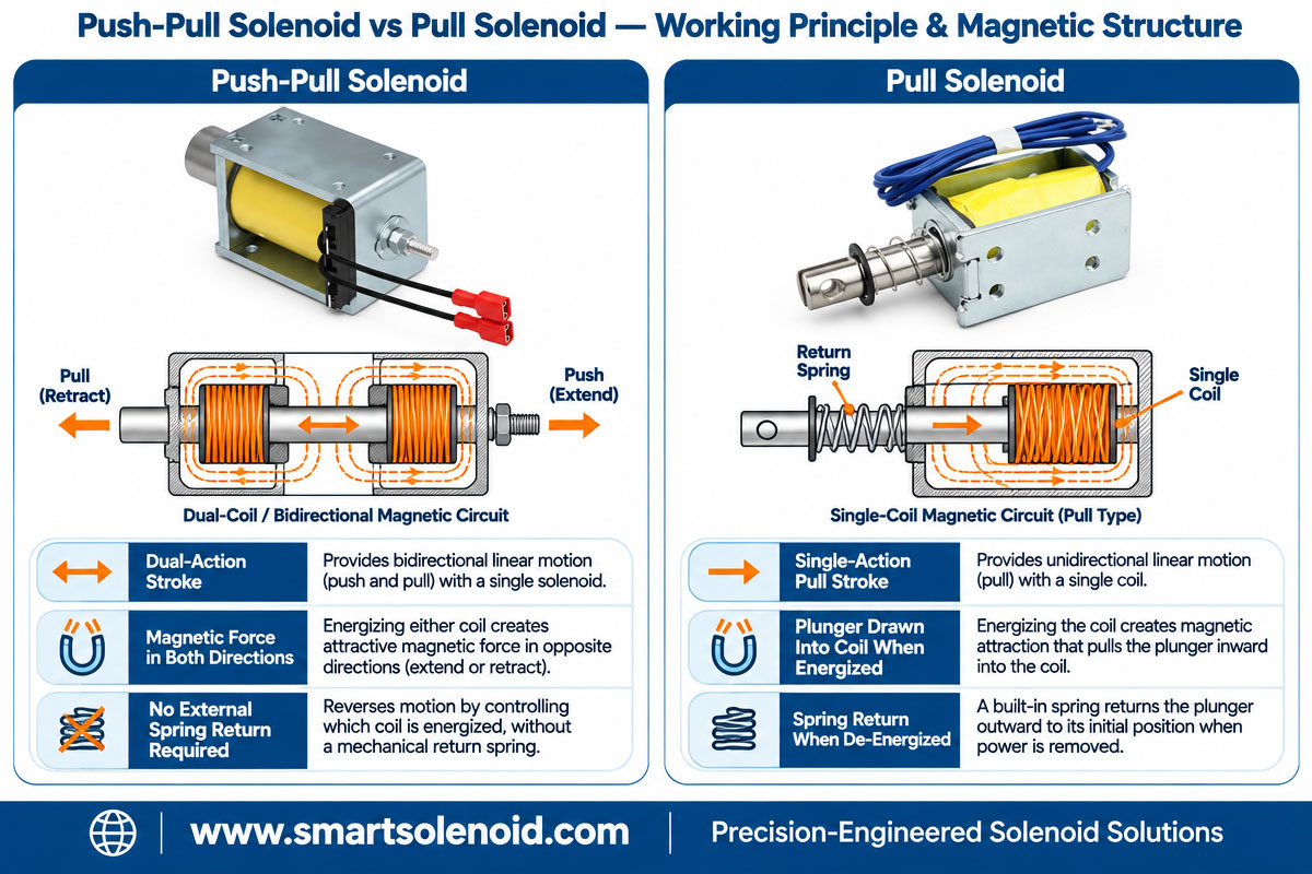
Both actuators are based on the same electromagnetic principle but differ in their magnetic and mechanical designs.
Magnetic Structure of Pull Solenoid
It is a typical pull solenoid. It uses a coil and magnetic housing to create an attracting magnetic field.
The plunger, when energized, moves toward the magnetic pole, decreasing the reluctance of the magnetic circuit.
Generally the smaller the air gap, the stronger the magnetic attraction.
When the coil is not energized, a return spring pushes the plunger outward.
This design is suitable for applications that require only one of the powered movement directions.
Push-Pull Solenoid Magnetic Structure
A push-pull linear solenoid can have a different plunger arrangement, mechanical linkage, or magnetic design to obtain the required output movement.
The design can include, depending on the application:
Long output shaft.
Custom plunger setup.
Different spring configurations.
Dual-coil magnetic design.
Special features for mounting and connection.
If you need to move some object in both directions, you can use two coils or some other special bi-directional setup.
The magnetic circuit has to be designed according to the force and stroke requirement.
This is especially important when the actuator has to overcome the mechanical load over the entire motion.
5. Variations in Force and Stroke Performance
Force and stroke are two of the most important characteristics while selecting an electromagnetic actuator.
Forces Characteristics
The output force of a solenoid depends on a number of factors:
Current in the coil.
Number of winding turns.
Magnetic substance.
Air gap.
Diameter of plunger.
Area of magnetic poles.
Design of magnetic circuits.
The simplified magnetic force relation is:
F = (B² A)/(2μ₀)
where
F = Electromagnetic force.
B = Magnetic flux density.
A = area of effective magnetic pole.
μ₀ = Permeability in free space.
This simplified formula allows understanding why the electromagnetic force depends on the magnetic flux density and pole area. The geometry, leakage flux, magnetic saturation, and plunger position influence the real performance of the solenoid.
Both types of actuators can be designed to meet different force requirements. There is no rule that one kind will always give larger force than another.
Stroke Performance
The stroke is the distance the piston moves.
A solenoid can be designed, for example, for 3 mm, 5 mm, 10 mm, or 15 mm stroke.
The longer stroke tends to make it harder to obtain enough force during the movement.
Engineers have to take into account the whole force-stroke characteristic and not choose a solenoid only by its maximum force.
A custom push-pull linear solenoid can be designed according to the actual mechanical requirements of the client’s equipment.
6. Electrical Characteristics and Duty Cycle
Also it is important to consider the electrical characteristics of the actuator.
Both pull solenoids and push-pull solenoids can be made for different operating voltages, including 5 V, 12 V, and 24 V DC.
The current in the coil under steady-state conditions is obtained using Ohm’s Law:
I = V/R, where
I = Current.
V = Voltage applied.
R = Resistance of coil.
The electrical power is
P = V · I = V · I
For example, the 12 V solenoid with a coil resistance of 24 ohms draws about 6 W of power in steady state.
Also, the duty cycle has to be considered.
Typical configurations include .
10% duty cycle for short intermittent use.
DUTY CYCLE FOR MODERATE INTERMITTENT OPERATION: 25%
50% duty cycle for more frequent triggering.
OPERATION CONTINUOUSLY WITHIN THERMAL LIMITS 100% duty cycle.
For coil winding in continuous energization applications, the diameter of the copper wire, insulation class, and heat dissipation have to be carefully estimated.
In some applications PWM control can also be used to provide high initial activation current and low holding current. It can allow the decrease of power consumption and temperature rise.
7. Advantages and Disadvantages of Different Solenoid Types

The right choice of the solenoid actuator depends on the exact application.
Benefits of Push-Pull Linear Solenoids
Versatility of motion configuration. It can be specially made to fit various push and pull applications.
Customizability. It allows tailoring of the solenoid force, stroke, and installation parameters.
A large scope of applicability. They find use in automatic machines, locking systems, and mechanical positioning devices
Design for OEM needs. It can be specially customized for any installation and connection requirements.
Potential Limitation
Complicated design of the structure might increase production costs
Special designs of bidirectional linear solenoids might have additional coils.
Parameters for force and stroke should be carefully optimized
Benefits of Pull Solenoids
Simplest possible design. Consists of the simplest coil and plunger.
Guaranteed functioning. They are used in cooperation with conventional spring return designs.
Simplification of control. The device operates on electricity through simple switching mechanisms.
Good cost-efficiency. A pulling-only solenoid may be cost-effective for some uses.
Limitations of Pull Solenoids
Limited directions of mechanical movement. Works only in one direction, pulling.
Some applications might require the use of some mechanical elements for the outward push motion.
Not all pull solenoids can be used for the powered bidirectional motion.
8. Selecting the Right Solenoid for Your Industrial Application
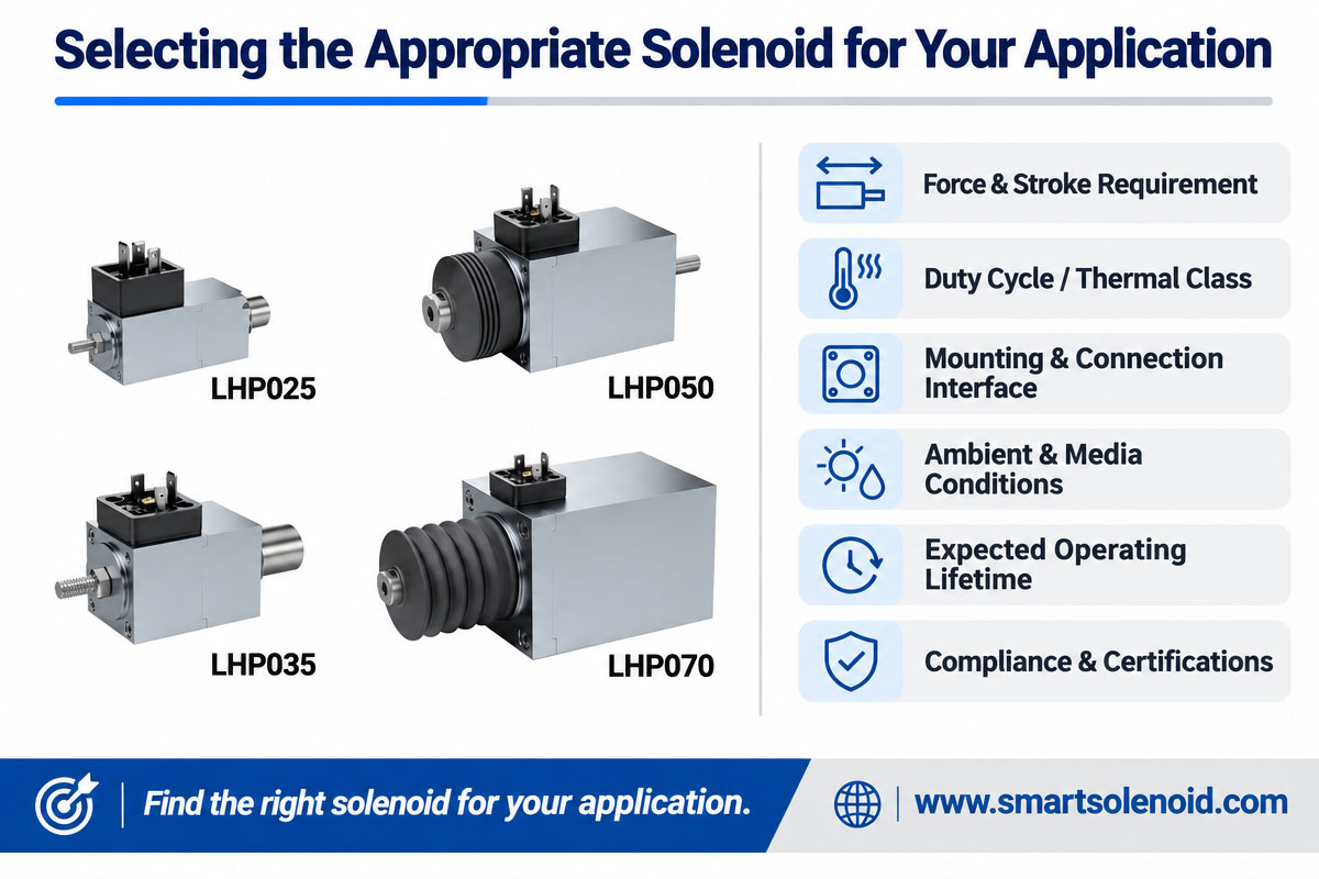
Each industry has different solenoid actuator requirements.
8.1 Automation Industry
For the machinery, linear motion actuation is required in order to perform positioning tasks or to control mechanical switches and release locking mechanisms.
The right actuator here would be the push-pull linear solenoid if there is a need for a particular configuration of mechanical push or pull output.
A conventional pulling solenoid may suffice for performing a simple operation of releasing or returning some item back.
8.2 Automobile Equipment and Components
There are many applications for solenoids in the automobile industry, including door locks, transmission units, mechanical release devices, and other electronically controlled devices.
The actuator in this case has to be made specially to withstand vibrations and other stresses associated with automotive devices.
8.3 Medical Devices
When working with medical devices, solenoids are needed for controlling the fluid and sample movement, as well as performing mechanical positioning.
Selection criteria for such devices are noise, heat resistance, working frequency, and reliability.
8.4 Security Systems and Electronic Locks
Solenoids are often used in security systems to disengage a locking component.
If there is a need for a particular pushing mechanism or a special installation design, then the push-pull linear solenoid is recommended for this use.
8.5 Automatic Vending and Dispensing Devices
These devices often have mechanical release levers, which require the use of an electromechanical solenoid actuator.
The device has to be capable of performing mechanical movement over and over again in order to satisfy the requirements of the machine.
8.6 Industrial Valves
An electromagnetic solenoid actuator may be applied to control the valves through operating the internal plunger or valve itself.
It depends on the type of the flow control structure, pressure, required force, and operating conditions.
9. Selection checking list for the appropriate solenoid
Before selecting a solenoid, it is necessary to define the complete set of technical requirements.
This includes the following information:
- Voltage: 5V, 12V, 24V, or other required voltages.
- Required force. Establish a minimum force of pushing or pulling during the operation.
- Stroke. Specify the required stroke in millimeters.
- Operating mode. Whether the solenoid is operated periodically or constantly.
- Operation frequency. Specify how many times it should be activated per minute or hour.
- Requirements for mounting and installation. Specify dimensions of the actuator and plunger.
- Direction of movement. Push, pull, spring return, or one- and two-way mechanical movement.
- Environment requirements. Temperature, humidity, vibrations, corrosion, etc.
- Lifespan. Required mechanical life.
By providing the manufacturer with a 2D drawing, 3D model, or even a sample, it would be easier for them to analyze your project and provide a suitable solution.
When there are special force, stroke, and mounting requirements, then a custom push-pull linear solenoid would fit the OEM application better.
10. Why choose Weilong for your custom push-pull linear solenoid supplier?
Weilong Intelligent Technology (Dongguan) Co., Ltd. has been a leading manufacturer of solenoids and inductors since 2007.
We are designing and developing custom electromechanical solenoid actuators for various industries such as automation, automotive equipment, medical devices, security systems, and others.
Manufacturing capabilities of our company include
metal stamping and tooling
injection molding of plastic
CNC milling
copper coil winding
assembling of the solenoid
performing testing and product evaluation
By means of these capabilities we can manage the production process and manufacture custom push-pull linear solenoids to fit customer needs.
Our engineering staff will analyze your project based on the voltage, current, force, stroke, duty cycle, dimensions of installation, environmental requirements, and lifetime.
We can customize
pull-type solenoid
push-type solenoids
linear solenoids—push-pull
tubular solenoids
latch solenoids
rotary solenoids
custom electromagnetic coils
In case your project requires a small solenoid, a powerful electromagnetic mechanism, or special installation configurations, we can cooperate with your team to develop the right solenoid solution for you.
We have certificates for quality management and product compliance, including ISO 9001, IATF 16949, CE, RoHS, and REACH.
Need the reliable push-pull linear solenoid manufacturing company?
Contact Weilong Intelligent Technology and discuss your project. Our staff will analyze your technical specifications and provide you with a custom electromechanical solenoid solution.
Web site: https://www.smartsolenoid.com Email: [email protected]
11: Frequently Asked Questions (FAQs)
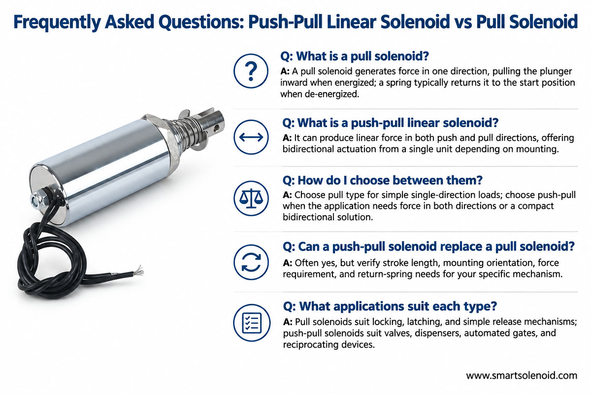
Q1. What is the difference between a push-pull linear solenoid and a pull-type solenoid?
A pull-type solenoid is made in order to produce the pulling motion inside when powered. The mechanics and magnetic structure of the push-pull linear solenoid allow producing the push or pull output motion.
Q2: Can the pull solenoid provide pushing motion?
The conventional pull solenoid, with the help of special mechanic linkages or installation, might provide pushing output. In general, its internal mechanics produce the inward pulling motion.
Q3: Is there a way to perform electrically driven motion of the push-pull linear solenoid in both directions?
There are bidirectional devices that can perform the powered motion in both directions. They use dual coils or special magnetic structures. With the help of a single coil spring return configuration, the solenoid performs powered motion in one direction and spring-driven movement in another.
Q4: Which solenoid produces more force?
Neither of these types is inherently stronger. Output force depends on coil design, magnetic structure, dimensions of the plunger, air gap, current, and stroke. Both can be designed to meet various force requirements.
Q5: Which stroke lengths are available?
Depending on the solenoid type, a stroke can be made to satisfy various stroke lengths, such as 2 mm, 5 mm, 10 mm, or longer stroke lengths. The force should be analyzed for the whole stroke.
Q6: Can a push-pull linear solenoid operate in continuous duty mode?
Yes, solenoid designs can be made to perform 100% duty-cycle operation. Proper coil winding, insulation, and operation conditions have to be defined for design.
Q7: What is the service life of a push-pull linear solenoid?
Service life depends on the operating frequency, mechanical loads, coil temperature, plunger design, and material quality. Such products can be designed for several hundreds of thousands of strokes or more than 1 million strokes depending on the application.
The service life should be analyzed by means of testing.
Q8: Does Weilong supply custom push-pull linear solenoids?
Yes, Weilong specializes in custom electromechanical actuators. We can customize voltage, current, force, stroke, coil winding, housing and mounting dimensions, and return mechanisms.
Q9: What information is needed for a custom solenoid quotation?
The client should provide voltage, required force, stroke, duty cycle, operating frequency, dimensions of installation, and environmental conditions. A drawing or sample of the product is also useful.
12: Conclusion
Both pull-solenoid and push-pull linear solenoids perform mechanically the same way using the electromagnetic force; however, the solenoid designs are different as well as the application requirements.
If your application requires the simple inward pulling and spring-return movement, then the right choice for you will be the conventional pull solenoid.
A push-pull linear solenoid gives more freedom in mechanical design and can be customized for pulling, pushing, and even powered bidirectional output.
The right solution depends on real force, stroke, electrical requirements, mounting, and operation environment.
If you are developing specialty equipment, then collaborating with the manufacturer of the solenoids will enhance the performance of your actuator design and avoid unnecessary design changes.
Weilong Intelligent Technology has a lot of experience in making electromechanical products and provides you with custom solenoids for industrial product development.
Contact Weilong now and discuss your requirements for push-pull linear solenoids.