Introduction to Ferrite Coil Inductance-Based Knowledge
Ferrite coil inductance is the electrical parameter that makes today’s electronics work well. Inductance affects energy stored in the magnetic field and the reaction of the coil to the variation of currents as well as interaction with other circuit parts. Ferrite-core coils have become rather popular among all kinds of inductors since they are capable of providing high inductance in comparatively small volume.
Ferrite coil inductance has an interest for engineers and designers of power supplies, electromagnetic components, and communications gear.
There are certain magnetic features of the material. Namely, they include relatively low electrical conductance and high magnetic permeability, which allow using ferrite cores in many high-frequency components and improve their performance as electromagnetic coils.
Below we are going to discuss in this guide the inductance of the ferrite core coil, the way it functions, the parameters affecting the performance, methods of its calculation, as well as the selection of an appropriate ferrite core for the particular application.
1. What Is Ferrite Coil Inductance?
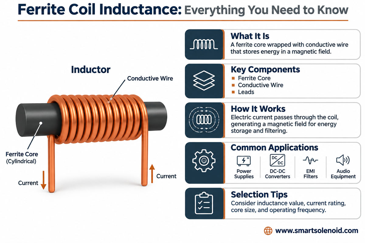
The ferrite coil inductance is the capability of a coil wrapped around a ferrite core to store energy in the magnetic field formed when electric current flows through the coil.
Ferrite coil inductance has its unit, which is the henry (H). However, smaller values are usually indicated in millihenries (mH) and microhenries (µH).
Flowing through the ferrite coil inductance, electricity creates a magnetic field. The core is providing a magnetic circuit if the coil is wound around it and helps to focus and increase magnetic flux.
With everything equal (layout, geometry, etc.), a coil on a ferrite core is always going to have much higher inductance compared to a similar coil wrapped around an air core.
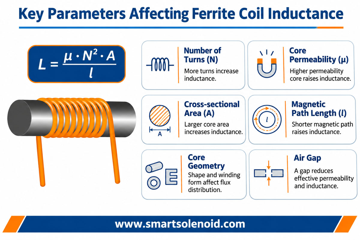
The ferrite coil inductance value depends on such factors:
Permeability of the magnet and ferrite material Number of turns on winding
Form and size of the core
Magnetic length
Air gap in the magnetic circuit
Working temperature and frequency Present level and magnetic saturation
The above-mentioned factors have to be used in order to design the coil since the required electrical characteristics cannot be achieved just by choosing a ferrite core for the given geometric characteristics.
2. How Does a Ferrite Coil Inductance Work?
Ferrite coil inductance is a kind of ceramic magnetic material composed usually of iron and some other oxides such as manganese, zinc, or nickel. Ferrite has magnetic properties that provide relatively high magnetic flux permeability. Wrapping the coil around the core makes magnetic flux from the winding trapped in the core.
This improves the inductance of the coil as well as the magnetic coupling of the windings.
The simple relationship of these features is shown below:
L = μN^2a/l
where:
L = inductance μ = magnetic permeability
N = Number of turns on the winding
A = cross-sectional area of core
l = effective length of magnetic circuit
The above relationship gives a simple explanation of the relation between core characteristics and winding layout. The actual value of inductance is dependent on the entire magnetic circuit with its air gap, magnetic flux leakage, winding geometry, and frequency characteristics of the core.
For example, the inductance of the ferrite core can be greatly increased by increasing the number of winding turns. However, the addition of turns is going to increase also the length of the wire, its resistivity, available space for winding, and maybe even additional parasitic capacitance.
Therefore, it is necessary to make some trade-offs between electrical performance and physical size and manufacturability of the core so as to get the optimal ferrite core design.
3. Key Parameters Affecting the Ferrite Coil Inductance
Some key design parameters define the final inductance value. Knowledge of these parameters is helpful for designers in order to design particular coils.
3.1. Ferrite Material Permeability
The permeability is the ability of magnetic material to provide passage for the magnetic flux.
Ferrite materials with different grades have different magnetic characteristics. Thus, some types of ferrite are used in the high-frequency power supplies; there are some types for signal processing, filtering, or electromagnetic components.
High permeability may help inductance to grow without the addition of new turns on the winding. However, high permeability does not necessarily mean high performance.
Selection of the particular material depends on frequency, temperature, magnetic flux density, core loss, and required stability of the inductance.
3.2 Number of Windings Turns
The number of turns affects inductance quite a lot.
If the magnetic circuit is simplified, then inductance is directly proportional to the square of the number of turns. Therefore, the inductance can be significantly raised using more winding turns.
However, adding turns brings some difficulties:
Additional wires are needed.
Additional resistance can be caused.
The space available for winding is restricted.
Possible increase of parasitic capacitance.
Production cost and time can grow.
The designer should define the optimal number of turns.
3.3 Form of Ferrite Core
Core form affects the magnetic circuit and cross-section area.
Some basic forms of ferrite cores are as follows:
E-cores are widely used in power transformers and inductors.
Toroidal cores provide a closed magnetic circuit with lower magnetic flux leakage.
U cores are used in many magnetic and electromagnetic assemblies.
Pot cores help to contain the magnetic field and to create compact magnetic structures.
In case of some antenna and signal applications, rod cores are used.
The proper choice depends on the coil’s purpose, available space for installation, magnetic characteristics, and assembly constraints.
3.4. Air Gap in the Magnetic Circuit
An air gap is the nonmagnetic gap introduced in the magnetic circuit of a core.
The introduction of an air gap usually decreases the permeability and inductance of the core for a given winding setup. However, it raises the tolerance of the magnetic circuit for DC-biased current before the saturation.
Air gaps are particularly crucial for the power inductors and some electromagnetic applications requiring exact controlling of current level and stored energy.
3.5. Working Temperature and Frequency
Frequency and temperature influence the magnetic properties of ferrites.
The core loss and permeability depend on temperature. There are various ferrite grades with distinct frequency bands.
Thus, it is required for the engineer to calculate the inductance of the component under realistic conditions instead of simple room-temperature conditions.
4. Calculation of Ferrite Coil Inductance
The quick calculation gives an estimate of ferrite core inductance prior to creation of the prototype.
For the simplified magnetic structure
L = μ₀ μᵣ N² A / l
where
μ₀ = magnetic permeability of free space μᵣ = magnetic permeability of ferrite material
N = number of turns
A = cross-sectional area of core (m²) l = length of magnetic circuit (m)
For instance, for a simplified ferrite core
Relative permeability = 1.500
Number of turns = 100
Cross-sectional area = 25 mm² Length of magnetic circuit = 50 mm
According to the simplified equation, the inductance equals approximately 9.42 mH.
The above calculation is approximate. The difference from the measured value can be caused by air gaps, magnetic leakage, core tolerance, winding setup, and working conditions.
For production purposes engineers prefer to use the AL value provided by the core manufacturer.
AL value is the inductance per squared turn, and it is given in nH per squared turn.
Calculation can be done in the following way:
L = AL × N²
For the core with AL value = 1,000 nH/turn² and with 100 turns, the inductance is estimated as:
100² * 1000 = 10,000,000 nH = 10 mH
The above-mentioned calculation can be used for preliminary calculations only. Actually, the inductance has to be measured in order to verify its real value.
5. Measurement of a ferrite coil inductance
Inductance accurate measurement is necessary for quality control, prototype testing, and production.
The common measuring tool for capacitance, resistance, and inductance is an LCR meter.
The basic steps of the measuring procedure are as follows:
Loosen the coil from its operating circuit.
Make an inspection for possible damage and problems with the connection.
Choose the inductance measuring range.
Connect the coil to the LCR meter.
Select measuring frequency.
Measure the value of inductance.
There is frequency dependence of magnetic properties of the material. So, it is necessary to consider measuring frequency. The coil can have various inductance depending on the test frequency.
Designers may want to check some more difficult characteristics for special applications:
Resistance, DC.
Dependence of impedance on frequency.
Quality factor (Q)
Losses At Heart
Saturation characteristics
Stability with respect to temperature
Inductance with DC bias
Measurement of inductance is not sufficient for electromagnetic component design since it has to be tested under working conditions.
6. Typical Application of Ferrite Core Coil
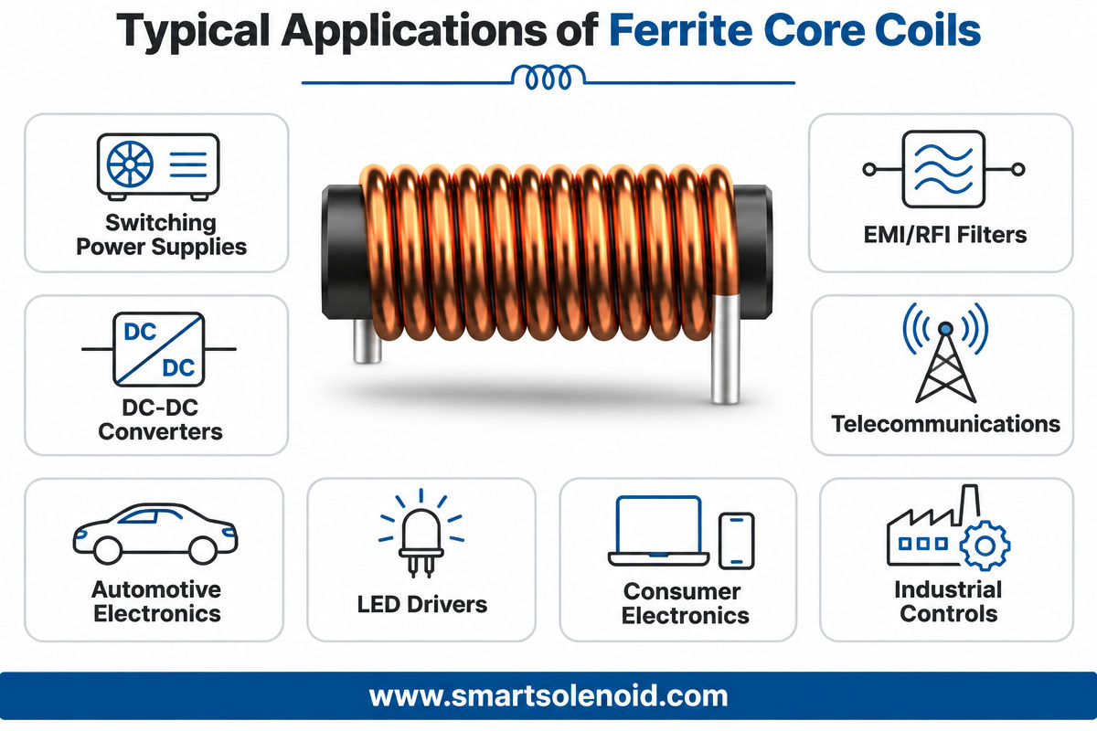
Ferrite core coils have wide application in various industries due to their magnetic features and the opportunity of making small components.
6.1 DC-DC Converters & Power Supplies
The ferrite core inductors are widely used elements in switching power supplies and DC-DC converters. They are applied to store and transmit energy and eliminate current ripple.
Choosing the right ferrite material allows reducing losses in the core at the desired switching frequency.
6.2 Electromagnetic Interference (EMI) Filter
Ferrite components are often used to suppress high-frequency electromagnetic noises.
They can increase electromagnetic compatibility of electronic devices, industrial equipment, and automotive systems.
6.3 Communications Equipment
Depending on the material grade and operating frequency, ferrite-core coils are used in some RF and signal processing circuits.
They provide filtering, impedance matching, and other magnetic functions.
6.4 Automotive Electronics
Modern vehicles are equipped with electronic control systems, sensors, and power management devices.
Ferrite parts are used in automotive power supplies, noise suppression, and other electronic assemblies. Such parts should be designed to withstand the required temperature, vibration, and electrical conditions.
6.5 Electromagnetic Actuator & Custom Ferrite Core Coil
Ferrite materials are also present in some special electromagnetic assemblies. However, the right core material is defined by the magnetic function.
For example, many linear solenoids use soft magnetic metal parts as cores, as they require a magnetic circuit that can produce mechanical force.
Thus, ferrite core coil and solenoid actuator coils are not the same products. Their magnetic design and requirements for performance can differ greatly.
7. Air Core vs. Iron Core vs. Ferrite Core Coil
One of the important aspects of coil design is choosing the right core material.
7.1 Main Material Ferrite
Ferrite cores are used in the manufacture of high-frequency magnetic components. They have a high electrical resistivity. At appropriate frequencies, they reduce eddy current losses compared to conductive magnetic materials.
7.2 Iron Heart
Iron-based magnetic materials can provide high magnetic flux density and were used in many low-frequency and high-power magnetic applications. Performance will depend on material and construction.
7.3 Air Core Coil
Air-core coils do not have any magnetic core material. They generally have a lower inductance for the same winding geometry, but they do not experience magnetic core saturation or core losses.
The best choice depends on frequency, current, magnetic flux density, size, efficiency, and cost.
8. Common Problems in Ferrite Coil Design
Even a well-designed coil can have performance problems if some important design factors are ignored.
Wrong Ferrite Material. Selecting the wrong material for the wrong frequency range can lead to excessive losses or unstable performance.
Magnetic Saturation. Excessive magnetic flux density can decrease the effective permeability and lead to inductance reduction.
Too much winding resistance. Thin or long wire will create excessive winding resistance. It leads to increased copper losses and higher temperature rise.
Poor thermal design. High current and core losses can cause overheating and reduce reliability and component lifetime.
Bad measuring conditions: Different test frequencies, temperatures, or methods can result in different results.
To prevent these problems, the engineers should define electrical specifications, select appropriate magnetic materials, calculate winding, and test the finished component.
9. How to Choose the Right Ferrite Coil Inductance
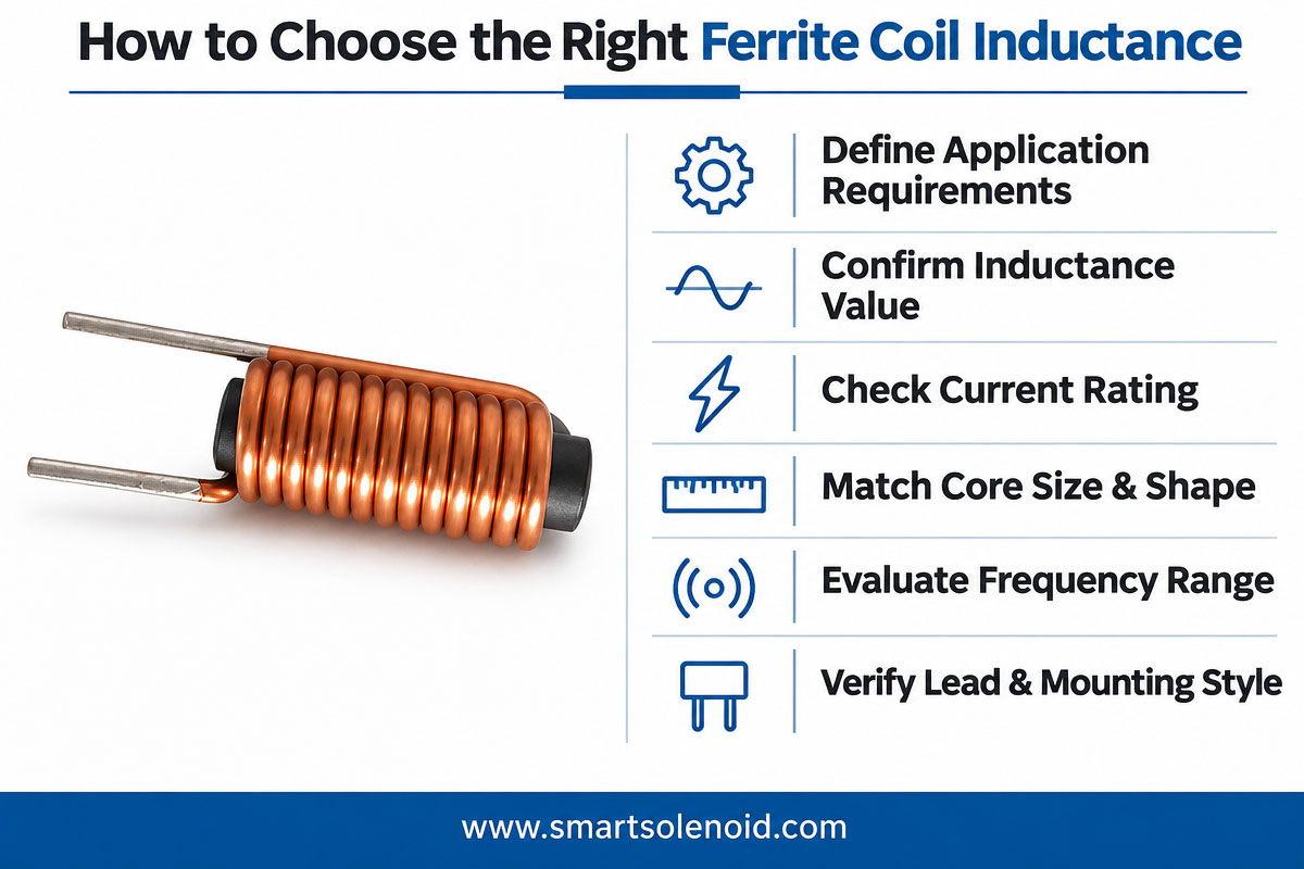
When selecting ferrite core coils for a new product, buyers and engineers should consider the following parameters:
Required inductance and tolerance
Operating frequency
Rated and maximum current
DC resistance
Material & core geometry
Max. operating temperature
Physical Dimension
Mounting and connection requirements
expected service life
Target price and volume of production
It is also important to provide the supplier with the intended application and operating conditions.
Complete specification will allow the manufacturer to determine whether the proposed core and winding design can meet the required performance.
If the design is not yet completed, it is recommended to make a prototype. With prototyping, engineers can test the key parameters, such as inductance, resistance, temperature rise, etc., before mass production.
10. Weilong Customized Electromagnetic Coil Maker
Weilong Intelligent Technology (Dongguan) Co., Ltd. produces solenoids and electromagnetic coils since 2007.
Weilong offers customized electromagnetic solutions for industrial automation, automotive systems, medical equipment, consumer products, and other industries.
The company has the following manufacturing capabilities:
Metal Stampings & Tooling
Plastic injection molding
Machine CNC
Copper winding coil
Electromagnetic Component Assembly
Product testing and performance assessment
Weilong’s engineering and manufacturing teams cooperate with customers to design components to meet their specific requirements, including voltage, current, inductance, resistance, force, stroke, duty cycle, dimensions, operating temperature, and installation environment.
Products include DC linear solenoids, tubular solenoids, rotary solenoids, latching solenoids, and customized electromagnetic coils.
When customers design a ferrite-core coil or other custom magnetic component, the first step is to define the required electrical characteristics and mechanical limitations. Weilong can review the demand of application and select the right manufacturing approach.
The company has quality management systems and certifications and compliance credentials, including ISO 9001, IATF 16949, CE, RoHS, and REACH, where applicable to products and operations.
For more information, visit www.smartsolenoid.com or contact Weilong to discuss your custom coil and solenoid requirements.
11. FAQ’s (Frequently Asked Questions) on ferrite coil inductance
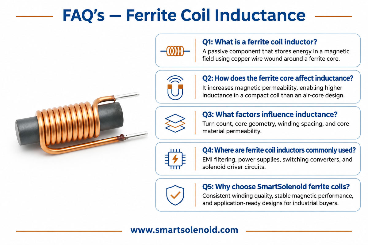
Q1: What factors determine the inductance of a ferrite coil?
The main factors are the permeability of the ferrite material, number of windings, geometry of the core, magnetic path length, operating frequency, temperature, and magnetic bias conditions.
Q2: How do you find the ferrite coil inductance?
Rough calculation gives $L \sim \mu_0 \mu_r N^2 A/l$. In real life, engineers usually use the AL value provided by the manufacturer for the ferrite core and calculate the inductance by the following formula: L = AL * N^2.
Q3: What makes a ferrite coil suitable for high-frequency inductors?
Ferrite has relatively high electrical resistivity, so eddy current losses are reduced compared to many conductive magnetic materials. Thus, proper grades of ferrite can be effectively used for high-frequency applications.
Q4. Does inductance increase on adding more turns?
Most times. Yes. In a simple magnetic circuit, inductance is proportional to the square of the number of turns in the coil. But more turns also increase the wire length, resistance, and space requirements of the winding.
A5: Yes, ferrite coil inductance is temperature dependent.
Yes. Ferrite permeability and magnetic losses are temperature dependent. The amount of change is a function of the ferrite material and the operating conditions.
A6: An inductance meter is used to measure the inductance of the ferrite coil.
The LCR meter is typically used. The measurement frequency and test conditions shall be according to the component specification for meaningful results. Yes, Weilong can make customized electromagnetic coils.
Yes. Weilong is a custom solenoid and electromagnet coil manufacturer. Customers can specify their electrical, mechanical, and environmental requirements for engineering review and product development.
12: Last Words
Ferrite core coil is a important components in modern electronic systems due to their useful magnetic features, small size, and good performance in many high-frequency applications.
To design a reliable magnetic component, you need to know the ferrite material, the number of winding turns, the core geometry, the air gap, and the operating frequency and temperature.
The correct calculation is a good first step, but it is also important to measure and test the prototype to validate the final performance.
When you are looking for custom electromagnetic parts, cooperating with the expert manufacturer can reduce risks in development and improve product consistency. Weilong Intelligent Technology has the manufacturing and engineering expertise to offer customized solenoid and coil manufacturing solutions.
Contact Weilong at www.smartsolenoid.com for your next ferite coil project.