Compact Tubular Pull Solenoid for Industrial Automation
Custom Tubular Pull Solenoid for Industrial Equipment
Tubular Pull Solenoid for Robotics and Automation Systems
Energy Efficient Tubular Pull Solenoid for Automation solution
Heavy Duty Tubular Pull Solenoid for Factory Machines guide
Precision Tubular Pull Solenoid for Industrial Control solution
Compact Tubular Pull Solenoid for Industrial Automation
Custom Tubular Pull Solenoid for Industrial Equipment
Tubular Pull Solenoid for Robotics and Automation Systems
Energy Efficient Tubular Pull Solenoid for Automation solution
Heavy Duty Tubular Pull Solenoid for Factory Machines guide
Precision Tubular Pull Solenoid for Industrial Control solution

WL2530 Industrial DC Tubular Pull Solenoid for Automation Solutions

The DC Tubular Pull Solenoid is a compact electromagnetic actuator that generates reliable linear pulling motion for industrial and automation equipment. The cylindrical design makes it possible to integrate a coil, magnetic circuit, and plunger in one unit. When current passes through a coil, a magnetic field is generated, attracting the plunger to the center of a solenoid. Such linear motion can move locks, latches, valves, clamps, and switches.

There are different diameters, lengths, voltages, strokes, and force ratings for tubular pull solenoids. Designers can also specify spring, mounting bracket, shaft, connectors, wire configuration, and finish. For industrial purposes designers take into consideration such parameters as starting force, holding force, duty cycle, operating temperature, response time, and operating life of the solenoid. Such a small size, simple control, and repeatable motion make tubular pull solenoids ideal for factory automation, material handling, robotics, access systems, dispensing machines, and custom electromechanical equipment.

DC Tubular Pull Solenoid Product Overview

The DC Tubular Pull Solenoid is a compact linear electromagnetic actuator for dependable pull applications. Inside the cylindrical body, there is an electromagnetic coil and a magnetic plunger designed to create controlled axial movement when excited. The product can be customized according to the application for different operating voltages, stroke lengths, pulling forces, duty cycles, and mounting requirements. There are options of return springs, custom shafts, connectors, lead wires, and mounting brackets. Tubular construction makes it possible to be installed efficiently in machinery with limited space without losing plunger movement ability. The device is designed for use in automation equipment, industrial locks, valves, robotics, conveyors, packaging machinery, dispensing equipment, mechanical release systems, and other customized electromechanical applications.

How does the DC tubular pull solenoid work?

1. Power is supplied.

Application of a DC voltage to the solenoid coil causes an electric current to pass through it.

2. Generation of the magnetic field

Exciting causes the creation of a magnetic field around the inner magnetic circuit.

3. The plunger is pulled in.

A magnetic field generates an electromagnetic force that pulls the ferromagnetic plunger towards the center of the coil.

4. Linear movement occurs.

The plunger moves along the axis into the tube-shaped housing. Thus providing the necessary pull motion to the mechanical mechanism.

5. Mechanical load transmission

A plunger drives a latch, valve, lever, clamp, lock, or other mechanical mechanism.

6. Power is switched off.

When the electric power is cut off, magnetic force decreases. If a return spring is installed, the spring pushes the plunger back to its initial position.

Actual force depends on coil power, air gap, magnetic material, stroke, plunger shape, voltage, and temperature.

Main Features of Tubular Pull Solenoid

Thanks to its features, the tubular pull solenoid is well adapted to the purposes of industrial automation. The cylindrical shape of the solenoid makes it small and optimizes space utilization for installation. They can generate a controlled linear pull force and fast electromagnetic response. Coils of the solenoids allow operation with standard DC voltages, such as 12V, 24V, and others. The stroke length, force, spring characteristics, mounting configuration, and electrical connections can be customized to the requirements. The tubular shape makes it possible to achieve a uniform alignment of the plunger to the magnetic core. Solenoids are designed for intermittent or continuous duty, high temperatures, long operating life, and harsh industrial environments, depending on design requirements.


DC Tubular Pull Solenoid Product Video Presentation

Industrial DC Tubular Pull Solenoid Datasheet

Brand Weilong Technology Model Number WL2530
Rated Voltage (V) DC 12 V, 24 V, 48 V, and 60 V Rated Power (W) 20-30 W
Work Model Tubular Pull Type Holding Force (N) 1-6 N
Stroke (mm) 2-6 MM Reset Time(s) 0.3
Service Life 300 Thousand Times Certification CE, RoHS, ISO9001,
Material Carbon Steel Housing with Zinc-Plated Coating Power Contact DC Socket
Install Style Adjustable Screw and Cap Tolerance of Dimension ± 0.1 MM
Water-proof None Insulation Class F
Hi-Pot Test AC 600V 50/60Hz 2s Non-excitation Holding Force 0
Working Temperature -10°C-100°C Duty Cycle 1-100%
Thread Depth (mm) 3-5 mm Payment Term TT, or LC at Sight
Sample Order Yes. Warranty 1 Year
MOQ 1000 pcs Supply Ability 5000 pcs per week
Delivery Time 30 Days Port of Loading Shenzhen

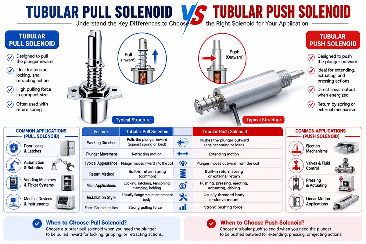
Tubular Pull Solenoid vs. Tubular Push

Solenoid

Tubular Pull Solenoid vs. Tubular Push Solenoid

The main difference is the direction and configuration of the plunger’s working movement.

Feature Tubular Pull Solenoid Tubular Push Solenoid
Main action Pulls the plunger inward Pushes the plunger outward
Typical mechanism The plunger retracts into the housing. The plunger extends from the housing.
Common use Locks, latches, release mechanisms Valves, push mechanisms, ejectors
Installation Often positioned to pull a linkage Often positioned to push a linkage
Spring design Often uses a return spring to extend the plunger Often uses a return spring to retract the plunger
Mechanical direction Inward movement Outward movement
Typical applications Door locks, clamps, releases Pushers, switches, valves, ejectors
Design priority Pull force at the required stroke. Push force at required stroke

DC Tubular Pull Solenoid

The tubular pull solenoid is made so that current passing through the coil pulls the plunger in. It is especially useful when machine mechanisms need the cable, lever, latch, or linkage to be pulled.

Typical applications are

Automatic lock systems

Release mechanisms

Industrial latches:

Safety Features

Cable pulling systems

Valve systems.

Self-locking clamps

Tubular Push Solenoid

The useful mechanical movement in the outward direction is performed by a push-type solenoid. This is correct if the actuator is meant to push another component.

Typical applications are

Ejectors

Push buttons

Valve operation

Product launch

Machine stop

Switchgear, automated

Positioning mechanisms

How to choose between push or pull?

Selection should be made on the basis of the direction of the force, stroke, load, installation position, and return mechanism.

If the machine mechanism needs the actuator to pull a component in the direction of the solenoid, select a tubular pull-type solenoid.

If the machine mechanism needs the actuator to push a component away from the solenoid, a tubular push solenoid is usually preferable.

For OEM industrial applications the most important parameter is not “pull” or “push,” but the force required at the working stroke.

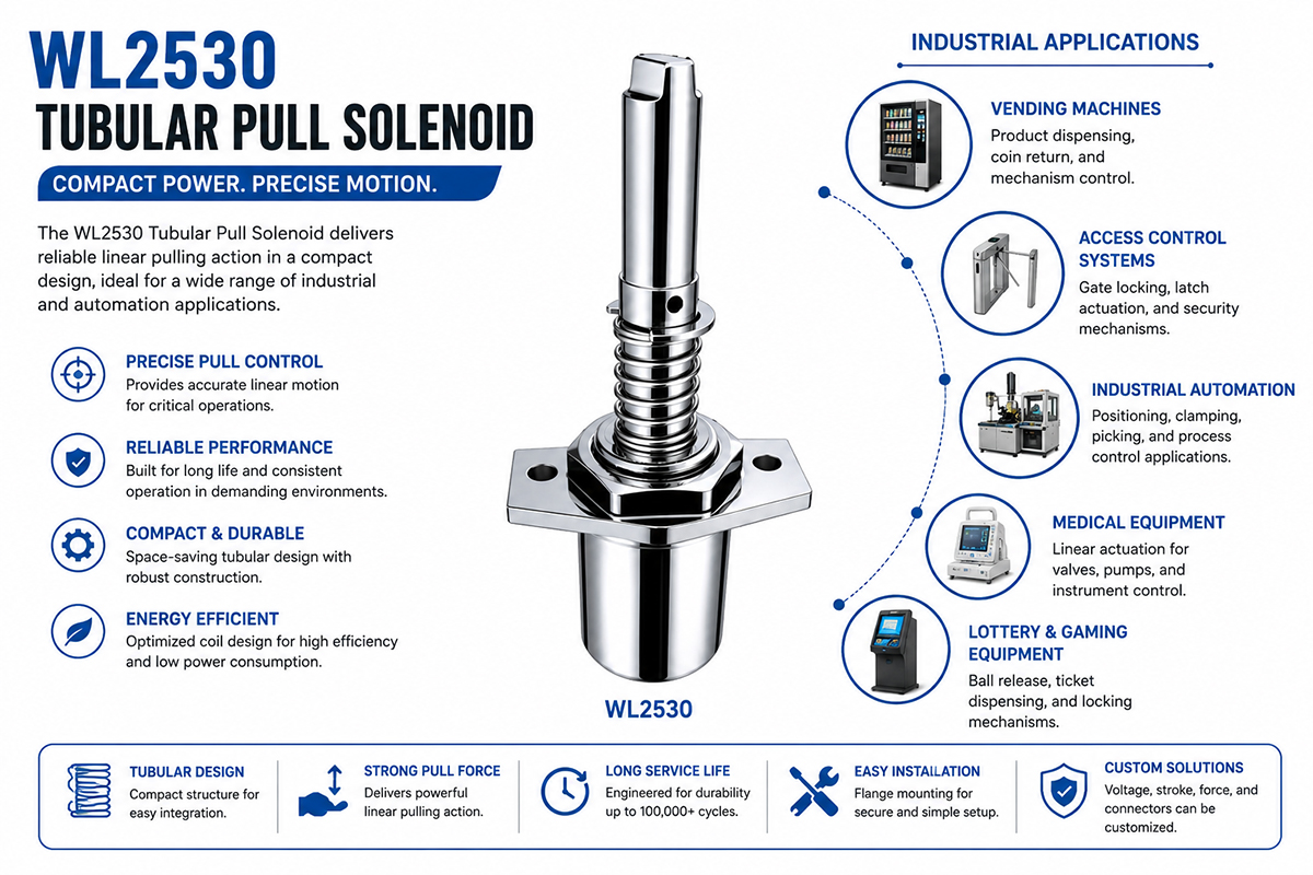
Industrial DC Tubular Pull Solenoid Industrial Application

DC Tubular Pull Solenoid Industrial Appliication Guide

DC tubular pull solenoids are widely used in industrial equipment due to their small size and controllable linear pull motion. In factory automation they can actuate mechanical locks, release mechanisms, positioning systems, and machine interlocks. Being repeatable, they are perfect for use in automated production lines where an electrical signal is needed to provide mechanical part motion.

Robotic tubular pull solenoids can actuate grippers, latches, mechanical release mechanisms, and auxiliary positioning devices. They can control gates, stops, locking mechanisms, and sorting mechanisms in material handling equipment.

Tubular pull solenoids can be used to control cutting, feeding, locking, clamping, and dispensing mechanisms of packaging machinery. Industrial valves have valve control assemblies that can be actuated by the suitable solenoids.

Also, they are used in access-control equipment, including automatic locks, door systems, and safety release systems. Small tubular solenoids are used in medical and laboratory equipment to control drawers, locks, valves, and positioning mechanisms with controlled linear movement.

Other applications include CNC machines, vending equipment, agricultural machinery, printing equipment, automated conveyors, parking systems, testing equipment, and custom industrial machines.

Force, stroke, voltage, dimensions, and duty cycle can be customized. Thus, it is possible to design tubular pull solenoids to meet the mechanical and electrical needs of specific industrial applications.

Why Are Tubular Pull Solenoids Getting Popular in Industrial Automation?

Modern machines require compact, controllable, and easily integrated actuators; thus, tubular pull solenoids have become more and more popular for industrial automation.

The space for installation of automation equipment is often limited. The tubular design allows placing the actuator directly inside or beside mechanical assemblies without increasing the actuator space.

Another significant advantage is the simplicity of electrical control. Solenoids can be energized by PLC, relay, transistor output, or specialized drivers. It means that an electrical signal directly causes mechanical movement.

They are also popular due to customization. Industrial equipment manufacturers often need a specific combination of force, stroke, voltage, duty cycle, dimensions, and mounting methods. All these requirements can be implemented around a tubular pull solenoid and not vice versa.

They also provide repeatable linear motion, which is very useful for automated locking, clamping, releasing, positioning, and switching mechanisms.

Also, a custom tubular pull solenoiwith the mechanical mechanical integration of OEM equipment. The plunger, spring, coil, housing, and mounting configuration can be optimized for a particular machine by the manufacturer.

Compact electromechanical actuators are a very important interface between the electrical control system and mechanical motion as the factories become more and more automated.


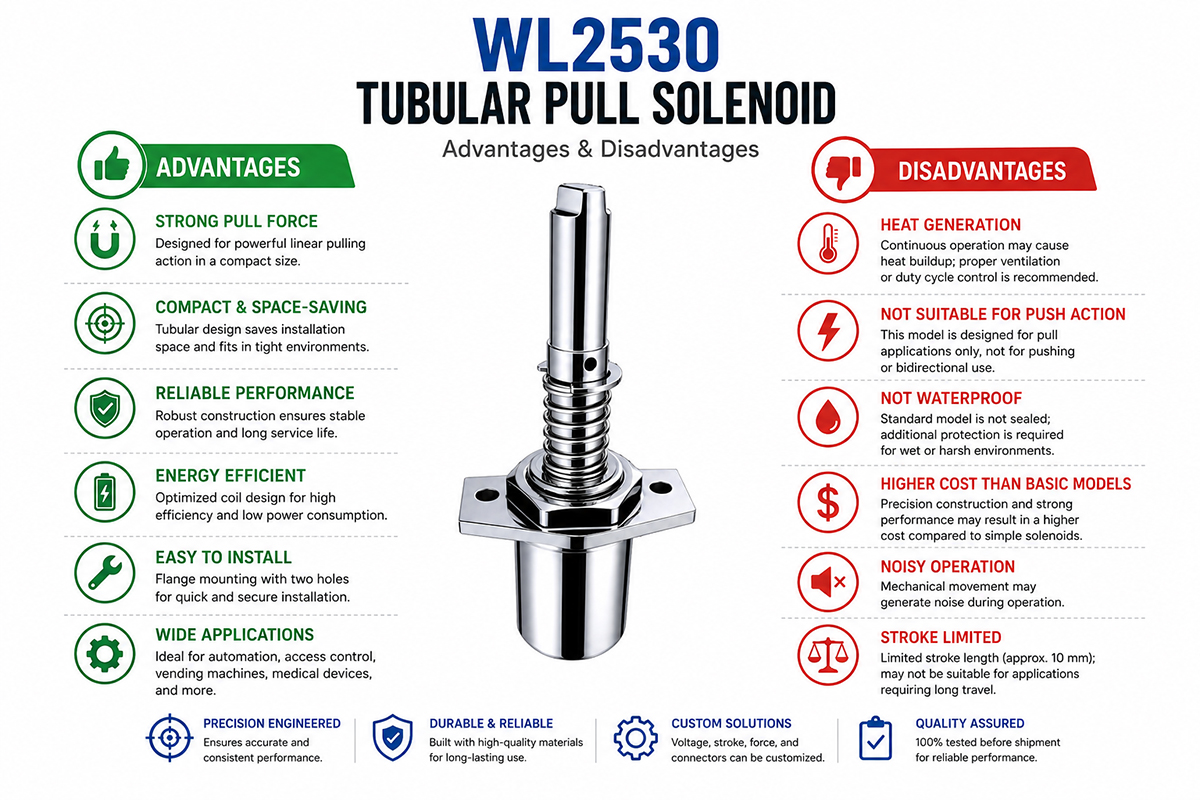
DC Tubular Pull Solenoid Advantage and Disadvantage

Tubular pull solenoids offer a good combination of compact design, controlled movement, and electrical actuation.

DC Tubular Pull Solenoid Advantages

Compact design: a cylindrical design allows using a tubular pull solenoid in narrow spaces in a machine.

Linear motion: The plunger producesdirect linear movement withoute mechanical transformation of forces.

Fast actuation: Electromagnetic actuation is capable of providing rapid movement for automated devices.

Customizable custom design for diverse applications: force, stroke, voltage, dimensions, spring force, terminals, and mounting configuration.

Simple control: Usually, a solenoid is controllable through an electrical switching circuit.

Movement repeatability: Well-designed units provide consistent movement over many operational cycles.

Integration capability: Tubular designs can be integrated into locks, valves, latches, clamps, and automated mechanisms.

DC Tubular Pull Solenoid Disadvantages

Force/Stroke dependence: The magnitude of the electromagnetic force of the solenoid is not constant over the plunger stroke.

Heat Generation: Continuous energization can produce considerable heat in the coil.

Power Consumption: A tubular pull solenoid, like any solenoid, as a device with power, consumes electrical energy to create magnetic force.

Mechanical wear: Piston surfaces, springs, and mechanisms can wear out after long operating periods.

Inefficiency: Some applications can have high electrical power consumption compared with mechanical output.

Sensitivity to environment: Dust, corrosion, temperature, and misalignment can affect performance.

For all these reasons, proper calculation of force, thermal characteristics, duty cycle, and mechanical parameters is needed before final design.

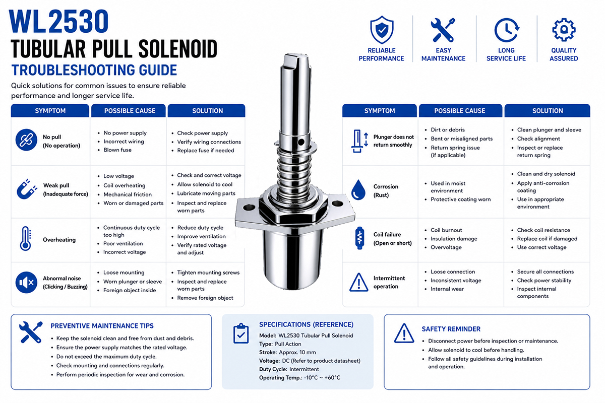
The DC Tubular Pull Solenoid Troubleshooting Guide

DC Tubular Pull Solenoid Troubleshooting Guide

First, the electrical system should be checked if a tubular pull solenoid doesn’t work correctly, followed by mechanical and thermal issues.

The solenoid is not working.

Check the power supply, connections, and control circuit. Measure the voltage across the solenoid terminals when powered. The solenoid may not move because of improper voltage or an open coil.

Not enough pulNot enough pulling power ensurer

Make sure that the load to be actuated is less than the solenoid force available at the stroke required. Check the condition of the plunger alignment, friction, spring force, and air gap.

Excessive heat generation

Overheating may be caused by improper duty cycle, high voltage, improper coil resistance, or improper heat dissipation. Check the real ON/OFF pattern of the operation.

Slow plunger

Causes of this problem can be mechanical friction, contamination, improper spring force, or low voltage. Please check the plunger and guide for any damage or interference.

Failure of plunger returning

If the return spring is present, verify the position and spring force. If the return spring is present, check the position and spring force. Ensure that the external mechanism doesn’t cause too much friction.

Too much noise.

Causes of the noise can be mechanical impact, improper mounting, high speed of the plunger, or magnetic vibration. Please check the stability of the mounting and end-stop construction.

Limited service life

Causes can be overheating, mechanical loading, misalignment, contamination, and improper materials.

If the problem still exists, test the solenoid under controlled conditions of voltage, load, stroke, and temperature to find out the reason for the malfunction.

6 Frequently Asked Questions About Tubular Pull Solenoids

1.What are the uses of Tubular Pull Solenoids?

Typical applications include industrial automation, robotics, machine locks, valves, packaging equipment, conveyors, dispensing systems, access-control equipment, and customized machinery.

2.What are the voltage options?

Tubular pull solenoids can be manufactured for a wide range of DC voltage requirements, such as 12VDC and 24VDC systems, which are commonly used. Custom voltage specifications can also be developed based on the application.

3.How to choose the correct Tubular Pull Solenoid?

Consider the following parameters: required pull force, stroke length, operating voltage, duty cycle, installation dimensions, return spring force, operating temperature, and service life. Force should be calculated at the real working stroke.

4.Can Tubular Pull Solenoid be made to order?

Yes. OEM solenoids can be made according to the specifications for diameter, length, stroke, force, voltage, spring, plunger, mounting configuration, lead wires, connectors, and other mechanical or electrical parameters.

5.How is a Pull Tubular Solenoid different from a Push Tubular Solenoid?

The tubular pull solenoid, being in the activated state, pulls the plunger inwards, while the tubular push solenoid is made to provide useful pushing outwards action. The correct type depends on the mechanical direction required.

6.How to extend the service life of Tubular Pull Solenoid?

Proper voltage and duty cycle should be used, no excessive mechanical loads should be applied, plungers should be aligned, and the operating temperature controlled. Reliability can also be improved by the use of suitable materials and testing of the solenoid in real working conditions.


How to Choose a DC Tubular Pull Solenoid

Choosing the right tubular pull solenoid goes far beyond the voltage and physical size of the device. The solenoid must match the mechanical and electrical requirements of the application.

1. Calculating necessary pulling force

At first, it is necessary to calculate the actual force needed to move the load. It is important to take into account such factors as friction, mechanical resistance, gravity, spring force, and safety margin. It is incorrect to choose a solenoid just because of the maximum force at zero stroke.

2. Setting the stroke

It is necessary to calculate the stroke of the plunger. In general, the stroke length changes the available force profile so it is necessary to assess the required force throughout the stroke.

3. Choosing operating voltage

It is necessary to specify the available power supply, such as 12VDC, 24VDC, or another voltage. The coil must be designed for the actual voltage and voltage tolerance.

4. Evaluating duty cycle

It is important to verify how often the solenoid is cycled and how long it stays energized. Intermittent duty and continuous duty applications require different thermal designs.

5. Checking installation area

It is important to measure the diameter, length, and mounting area available. Tubular solenoids are available in a variety of sizes, but their physical dimensions must be sufficient for the plunger stroke.

6. Observing return requirements

If it is necessary to move the mechanism when the power is off, you must choose between a return spring and external mechanical force.

7. Conditions of the environment

It is necessary to consider the temperature of operation, humidity, dust, vibrations, and corrosion exposure. The materials, coating, and insulation should be appropriate for the environment.

8. Finding the life expectancy

In industrial applications, tens of thousands or hundreds of thousands of cycles can be required. The mechanical design should not be finalized until the required life is specified.

9. Assessing the assembly and connection

It is necessary to specify mounting holes, brackets, threaded shafts, connectors, and wire length.

10. Testing complete assembly

Before mass production it is important to test the solenoid at actual voltage, load, stroke, temperature, and duty cycle.

Tips to avoid common design blunders

There are several common mistakes that can be made in the design of a tubular pull solenoid, which can result in poor performance, excessive heating, or early failure.

1. Avoid specifying only the maximum force

It is necessary to specify force at some stroke position. Solenoid force depends dramatically on the plunger position.

2. Duty cycle is often forgotten.

Continuous energization of the solenoid designed for intermittent duty can overheat the unit. Proper ON time, OFF time, and frequency of operation must be defined.

3. Don’t make the coil too big.

A big coil does not mean a suitable solution. Power consumption can increase and add to the heating and power costs.

4. Check the return spring.

A strong spring adds to the force needed. A spring that is too weak cannot return the plunger.

5. Provide adequate mechanical clearance.

Misalignment of the plunger with the external mechanism will increase friction and reduce life.

6. Think temperature

Coil resistance will increase due to temperature rise, and it will affect current and performance. Testing in thermal conditions is crucial.

7. Verify the actual power supply.

Nominal 24V. Voltage can vary. The solenoid should be tested in the expected operating voltage range.

8. Test the whole mechanism.

You cannot test the solenoid in isolation. Test the entire assembly consisting of load, spring, linkage, and mounting.

Get A Free Quote Now

Contact Form

Related Products

Related News

Scroll to Top

Get A Free Quote Now !

Contact Form
If you have any questions, please do not hesitate to contact us.
Weilong Solenoid Company Culture
