
Introduction on the Calculation of DC Linear Solenoid Force
The choice of a sufficiently powerful actuator is crucial to provide reliable operation of industrial equipment. The DC linear solenoid is a device that converts electrical energy into linear mechanical force. The force available is a function of the plunger’s stroke position, the coil, voltage, and load.
When the chosen actuator does not have enough force, it may fail to perform its whole stroke or operate unreliably. An oversized actuator, in its turn, will lead to unnecessary energy consumption, bulky installation, and an expensive project.
This guide shows how to calculate the required force of the DC linear solenoid, how to take into consideration the mechanical resistance, how to understand the dependence of the force on the stroke, and how to choose a reliable actuator.
1. Understand the resisting forces in a solenoid
Identify all the forces that prevent the plunger from moving before determining the required force.
The most widespread forces are, for instance,
External Load: The force needed to move the loaded part.
Spring resistance: The force to compress or expand a spring.
Friction—The resistance to sliding motion on guides, seals, sliding components, or attached mechanisms.
Gravity: The force if the actuator moves a mass upwards.
Acceleration: The force to move the masses to the desired velocity.
At each point of the stroke, the required electromagnetic force must overcome all resistance.
Here is the formula for calculating a simple system in one direction:
Required Force = External Load Force + Spring Force + Friction Force + Gravity Force + Acceleration Force
Use those terms only if they are relevant for your application. And keep in mind the directions of the forces.
2. Use the Basic Force Calculation Formula
For a DC linear solenoid to move a mass horizontally at a constant speed, the required force is calculated as follows:
Required Force = Load Force + Spring Force + Frictional Force
Suppose that your mechanism needs the following forces:
External load: 8N
Spring resistance: 3 N (0.67 lbs)
Friction: 1.5 N
The theoretical sum of forces is
Required Force = 8 + 3 + 1.5 = 12.5\text{ N}
It means that the actuator should be capable of producing at least 12.5 N of force at the given stroke position.
Engineers usually add enough margin to cover possible variations in friction, voltage, temperature, manufacturing tolerance, and load. It can’t be a fixed arbitrary margin since there is no universal one. Engineers should calculate the margin based on the risks and requirements of the application.
3. Determine the Spring Force
Spring-return solenoid systems often use a return spring. Also, Hooke’s law can be applied for estimating the force needed to compress the linear spring:
Spring force = Kx +
Location:
(Spring force = spring force in newtons (N) (k) = spring rate in newtons per meter (N/m) (x) = spring displacement in meters (m))
For instance, you have a spring with a spring rate of 800 N/m compressed by 5 mm, or .005 m.
[Spring force=8provides a resistance ofgives the resistance equal 4 N at this stroke.
In addition, you should also take into account the initial force of the pre-loaded spring. Sometimes, the spring force varies over the stroke. In this case you should calculate it at different stroke positions.
For the spring-return DC linear solenoid, the electromagnetic force is greater than the load force, the spring force, and the friction force for providing the required stroke.
4. Consider the Force-Stroke Relation
The relation between force and stroke length is one of the most important parameters for selecting an actuator.
Usually, the DC linear solenoid does not generate the same force over the whole stroke. For instance, it happens in most of the conventional DC linear solenoids, in which the force increases when the magnetic gap becomes smaller. It means that the force is smaller near the start and becomes larger near the fully attracted position of the plunger.
Here is the example of the force that can be provided at each point of the stroke:
Plunger Position Force available
0 mm 6 N
2 mm 10 N
4 mm 15 N
5 mm 18 N
These figures are for demonstrative purposes only and are not the specifications for the particular products.
If your mechanism requires 12.5 N in a 5 mm stroke, then the above-mentioned example of the actuator will not be sufficient at the start point of the stroke and at the position of 2 mm, although the final force is 18 N.
Therefore, always compare the force of your mechanism with the force of the actuator along the whole stroke. Preferably, try to get the force-stroke diagram from the manufacturer.
5. Acceleration and Mass in Motion
If the application requires quick motions, your actuator may have to provide some additional force to accelerate the moving masses.
From the second law of Newton we have:
Force = ma = acceleration force
Where:
(m) = total moving mass in kilograms kg
(a) = acceleration required in meters per second squared (m/s²)
Let’s suppose the moving mass is 0.2 kg and we want to accelerate it at 5 m/s²:
[Acceleration force }= 0.2 × 5 = 1 \text{ N]}
The additional 1 N is to be taken into account in the sum with load, spring resistance, and friction.
For high-speed applications the mechanical shock, rebound, and response time of the electromagnetic fields should be considered as well.
6. Verify Voltage, Current, and Duty Cycle
A particular DC linear solenoid cannot be selected only on the basis of mechanical calculations. The electromagnetic performance of the actuator depends on the operating electrical parameters.
Voltage and current: The coil has to be operated within the range of the specified voltage and current. The availability of the force drops with a decrease of the supply voltage, depending on the coil and magnetic designs.
Duty Cycle: The solenoid, which is designed for an intermittent duty, will overheat if it works continuously. The operation and the parameters of the coil depend on its temperature.
Temperature: Higher temperatures and insufficient cooling will affect the allowed operating current and/or the duration of energizing.
Installation conditions: Any misalignment, extra friction, and mechanical interferences prevent the actuator from completing its stroke.
Therefore, engineers should verify that the required force can be generated under actual conditions of the voltage, temperature, duty cycle, and installation as opposed to theoretical ones.
7. Practical checklist for selection of the DC linear solenoid

Have the following data ready before requesting a quotation or prototype:
Required force: State the minimum usable force in newtons or gram-forces.
Stroke Length: The required distance in millimeters.
Load conditions: State the external load. Does it change along the stroke?
Return mechanism: Find the spring rate or pre-load and/or return force.
Electrical requirements: Limits of DC voltage, current, or power and duty cycle.
Operating Speed: Find out the speed and frequency of operation needed.
Installation Dimensions. Maximum dimensions (length, width, height) and mounting details.
Environment: Ambient temperature, dust, moisture, vibration, etc.
Volume of production. The required volume of production and a prototype.
Then the manufacturer will evaluate the feasibility and suggest the design.
8. Weilong Custom DC Linear Solenoids

Weilong Intelligent Technology (Dongguan) Co., Ltd. specializes in the manufacture of solenoids and inductors of custom configuration for industrial and OEM applications. The company, established in 2007, manufactures devices for applications requiring particular force, stroke, voltage, dimensions, duty cycle, and mechanical configuration.
The company has manufacturing capacities as follows: metal stamping, tooling, plastic injection molding, CNC machining, coil winding, and assembly.
If you are developing the custom DC linear solenoid device, you are welcome to send us your application drawings, 3D models, required force and stroke, electrical parameters, and quantities.
Custom configurations depend on the particular project, but they usually include the plunger construction, return spring, magnetic circuit, coil, mounting, and electrical connections.
The feasibility of the project is the sum of force, stroke, power, temperature, size, and cost.
The OEM buyers test prototypes under realistic load conditions before mass production.
You can request such tests from the Weilong sales department by e-mail:
[email protected] or mobile phone/ Whatsapp: 86 136 42 98 0378 9
9. Conclusion on the Calculation of DC Linear Solenoid Force
The first step for calculating the required force of the DC linear solenoid is defining the resisting forces as external load force, spring force, friction force, the gravity force, and acceleration force. After that the sum is compared to the actual available force at the stroke position.
For reliable operation it is also important to verify voltage, current, duty cycle, temperature, and installation.
With the accurate definition of application requirements and verification of the parameters against manufacturers’ data and testing, the engineers will be able to choose the actuator balancing force, stroke, size, power, and cost.
Weilong Intelligent Technology (Dongguan) Co., Ltd. can review your requirements and suggest the appropriate solenoid solutions for your custom application.
10.Common Questions on the Calculation of DC Linear Solenoid Force
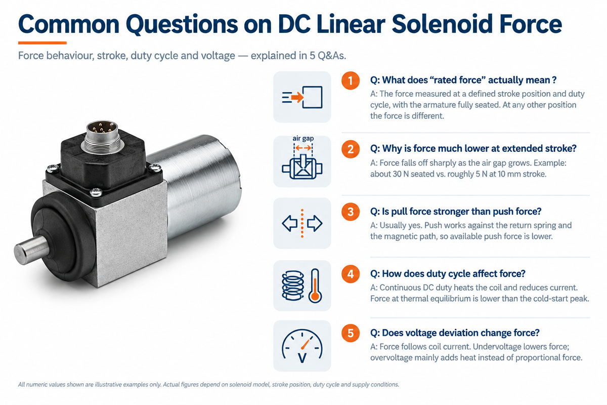
1. How do you calculate DC linear solenoid force?
To add up the external resisting load force, spring force, friction, gravity (if applicable), and acceleration force. Then to make sure that the actuator can provide the required force at all stroke points.
2. Is the force of the solenoid constant over the stroke?
No. The force is normally varying along the stroke because the magnetic air gap is changing. Therefore, the force-stroke diagram has to be always verified instead of trusting only one maximum force rating.
3. What safety factor should I use?
Correct margin is the compromise between the load variation, friction, voltage, temperature, manufacturing tolerances, and possible consequences of the failure. It should be defined based on the application requirements and validated by testing.
4. More voltage means more force, correct?
Not necessarily. The force depends on the coil design, current, magnetic geometry, temperature, and magnetic saturation. Use rated operating conditions and performance data provided by the manufacturer.
5. Can Weilong customize the stroke and force?
Custom Solenoids for OEM Applications Weilong manufactures. The technical feasibility can be evaluated by looking at the stroke and force requirements together with the voltage, duty cycle, installation dimensions, and quantity of production. For more information about Weilong Technology, please visit www.smartsolenoid.com.