
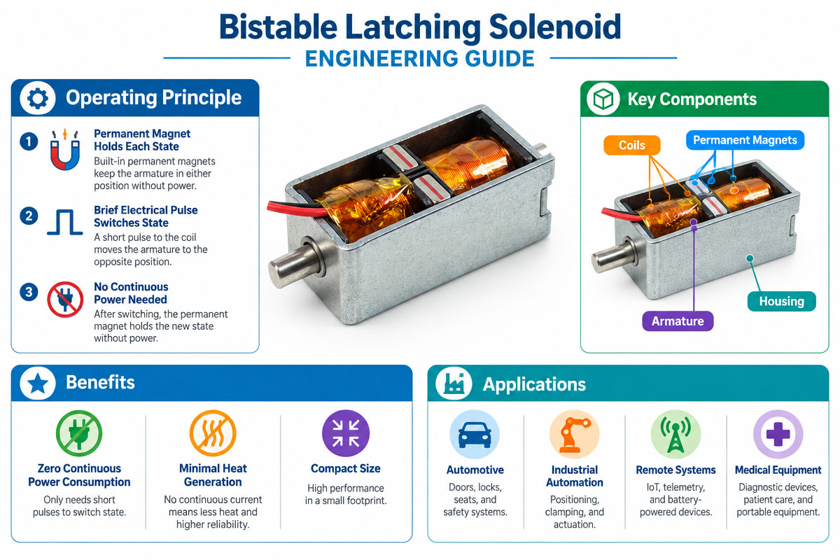
 Introduction to Latching Solenoid Engineering Solution
A bistable latching solenoid is an electromechanical actuator that operates in two mechanical states and retains its state without power consumption. Due to its features, this type of solenoid finds wide use in low-power, compact linear actuators and in other types of position holders.
DC solenoids need continuous power to the coil to hold the actuated state. In contrast, bistable solenoids usually operate by magnetic latching of the actuator position after the electrical pulse has terminated.
The second electrical signal moves the actuator to the other state.
This principle offers numerous advantages in battery-powered devices, access control systems, electronic locks, industrial automation, medical equipment, metering devices, safety devices, and in many other applications that require a power supply only in state-changing moments.
A bistable latching solenoid engineering solution takes into account force parameters, magnetic holding performance, pulse energy, coil design, mechanical load, temperature, tolerance, lifetime, control electronics, and operating environment. The following guide describes all these points.
1. What is a bistable latching solenoid, and how does it work?
A solenoid serves to convert electrical energy into mechanical energy in a linear way.
Current flowing through the coil creates the magnetic field, which interacts with the magnetic circuit and generates force on the movable actuator (armature or plunger).
In a usual spring-return solenoid, the removal of electrical power enables the spring or external load to bring back the plunger to its initial position.
But a bistable latching solenoid operates in the other way.
It shows two stable mechanical states. Once the actuator reaches one state, the magnetic system helps to keep this state without continuous coil current.
The second electrical signal sent by the control system changes the actuator state. Often, it means changing the polarity of the coil according to the magnetic circuit design.
This means that most of the power supply is spent on changing position.
And this is very beneficial for bistable operation since the device spends most of its time in one state and rarely changes its position.
2. The differences between the single latching vs. bistable latching solenoids
Engineers should know the difference between bistable and monostable operation.
A monostable solenoid shows only one primary stable position. When the electromagnetic force disappears, the spring or another mechanical force returns the actuator to that position.
In a bistable actuator, there are two stable positions.
Let’s look at an electronic locking system as an example.
The first electrical pulse moves the locking pin to its locked position. After this, the pin is held in its position even when the electrical pulse ends.
A reverse electrical pulse changes the actuator mechanism to the unlocked position, which is also held after the electrical pulse ends.
Neither position requires a continuous power supply to retain.
It is one of the reasons why bistable latching solenoids are useful in low-power devices.
However, designers should remember that the actuator retains its position even during power failure.
3. Determination of Required Stroke
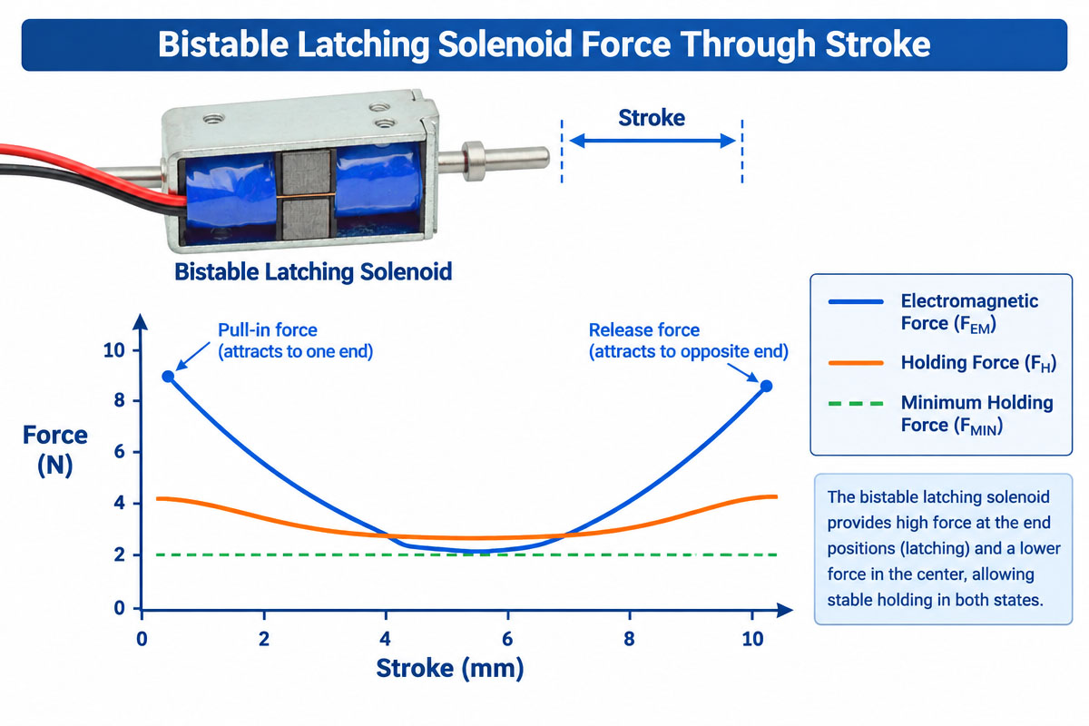
A stroke is the entire linear path from one stable position to the other.
Several millimeters of stroke may be enough for typical AP, but some mechanisms need longer strokes.
Engineers should not specify unnecessary travel.
Impact of stroke increasing:
Available force
Efficiency of magnetic circuit
Solenoid dimensions
Plunger weight
Response time
Required electrical power
If a lock needs 4 mm of stroke, designing a longer stroke increases the size or efficiency of the solenoid without any necessity.
During the design of a bistable latching solenoid, engineers should know the full mechanical mechanism and determine the minimum stroke value with proper tolerances.
4. Evaluation of the bistable latching solenoid force through the stroke
A solenoid usually does not show constant force during the whole travel.
Available electromagnetic force depends on the position of the plunger and magnetic air gap.
In any case, this can make the force specification misleading.
Suppose that the application requires the following:
stroke—6 mm
Start force—8 N
intermediate force—12 N
final force—20 N
In such a case, if the solenoid can provide 20 N only at the end of the stroke but cannot provide 8 N needed to start moving, it cannot work correctly.
Therefore, when it is possible, engineers should check the force/stroke graph.
Also, the mechanical load should include:
spring force
friction.
gravity
resistance of linkage
seal
mechanical tolerance
accelerating
contamination effects
The selected bistable latching solenoid should be able to provide enough force in the whole working range, not only at some point.
5. Understanding of Magnetic Holding Force
Actuating force is not equal to holding force.
Actuating force moves the plunger. But holding force retains the required position after the electrical pulse ends.
In bistable design, holding performance is probably the main engineering parameter.
Force required for holding depends on application.
A small internal switching mechanism requires relatively low force for holding. But a heavy lock or industrial mechanism requires much more.
Engineers should know if external loads, vibrations, shocks, springs, or mechanical tolerances overcome the magnetic holding force.
Therefore, the magnetic circuit of the bistable latching solenoid should be designed with consideration for both movement and position retention.
It is especially true for security or safety products because performance validation should always be performed on the whole mechanism.
6. Choice of Operating Voltage
Common DC operating voltages can be:
3 VDC
5 VDC
6 VDC
9 VDC
12 VDC
24 VDC
Other coil voltages are available.
Voltage choice should be coordinated with the electrical architecture of the product.
However, voltage alone is not a criterion for the selection of a solenoid by engineers.
Important electrical parameters are
voltage—potential supplied to the coil
coil resistance—together with applied voltage determines the behavior of current
affects electromagnetic force and power consumption
pulse length—defines how long the coil is energized during actuation
energy per pulse—confirms that there is enough mechanical work to make the transition
Current and pulse energy are especially important in battery-powered systems.
7. Optimization of the bistable latching solenoid Pulse Length
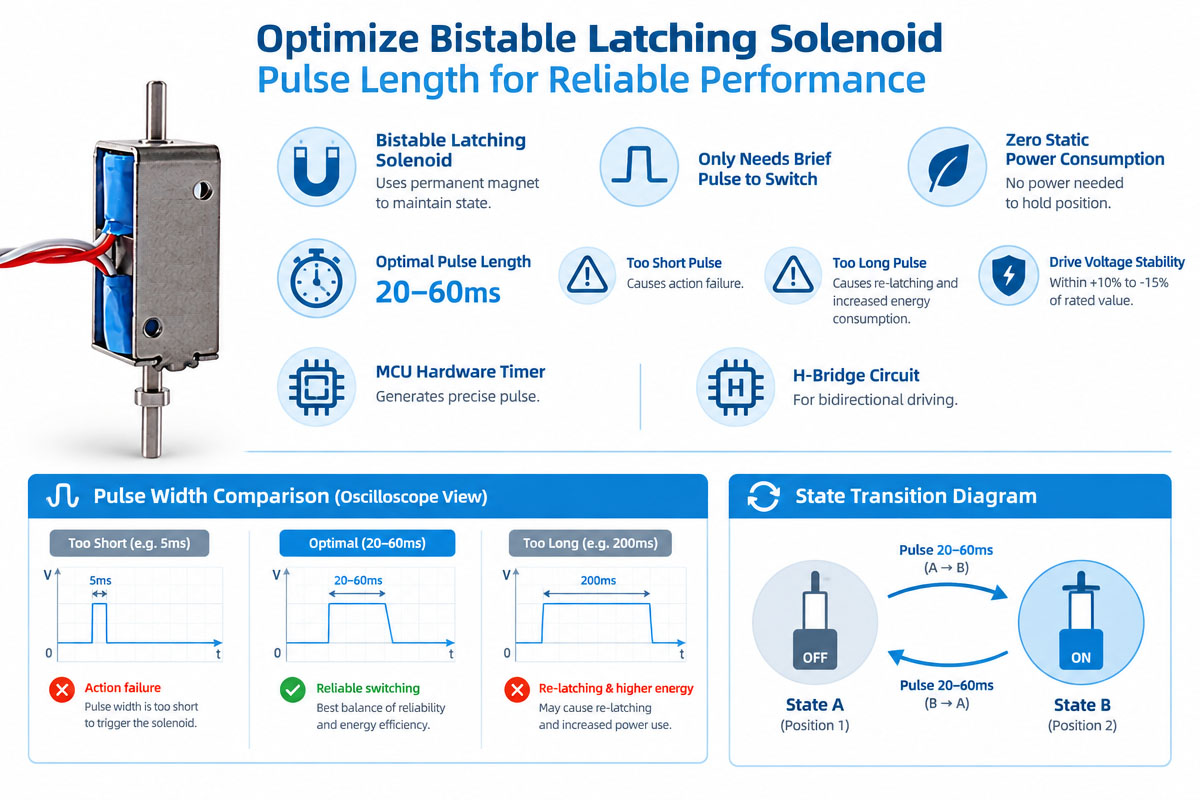
One of the main engineering advantages of this bistable design is that the coil does not require continuous power to stay in a stable state.
Or it is possible to use short pulses to change actuator position.
For example, one application can work with:
voltage – 12 V DC
pulse length—100 ms
operating frequency—20 times per day
For other applications, 300 ms pulse length is necessary due to heavier mechanical load or longer stroke.
Pulse length depends on the coil, magnetic circuit, mechanical load, stroke, voltage, and available current.
If the pulse is too short, the bistable latching solenoid may not complete its movement.
But a longer pulse wastes energy and causes excessive heat.
Prototype testing should establish reliable pulse length under worst-case conditions, not only minimal working pulse in one sample.
8. Pay Attention to Polarity Reversal and Drive Electronics
Many bistable solenoids change their state by polarity reversal of the current through the coil.
This means that drive electronics should be able to control polarity.
Dependent on the product architecture, engineers should use an H bridge or similar switching circuit.
Drive electronics design should be based on
coil voltage
maximum current
pulse length
switching frequency
inductive process
protection needs
available battery or power supply
Specific attention should be paid to inductive loads when the current is switched off.
A bistable latching solenoid and its driver electronics should be developed as one system, not as separate elements.
Under low-battery or worst-case voltage conditions, the mechanical operation may be unreliable if electrical drive electronics cannot provide enough current.
9. Assessment of Power and Energy Requirements
For low-power applications, instantaneous current is not the only figure of merit; engineers should also consider energy per operation.
A bistable actuator can spend relatively high current during a short time, spending little total energy per day due to the absence of the holding current.
It means that it is attractive for:
Smart locks (battery-powered)
IoT gadgets
Portable equipment
Electronic lockers:
Remote Control Systems
Smart meters
Automations aware of energy requirements
When selecting a bistable latching solenoid, engineers should estimate total daily energy consumption, including typical pulse length and number of operations.
Also, engineers should check worst-case battery-to-voltage and internal resistance. A new battery may have different voltage characteristics near its end of life.
10. Check the bistable latching solenoid’s Thermal Performance
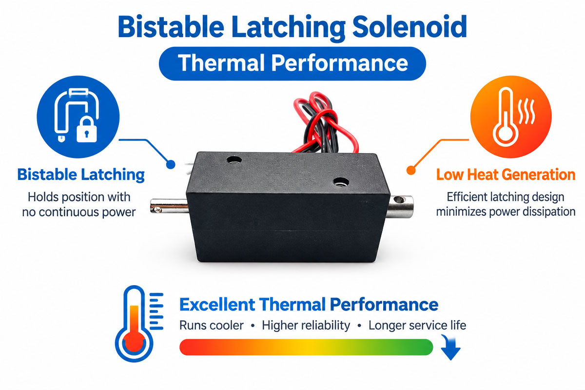
Proper thermal advantages can be gained with bistable solenoids since they are supplied with electricity for a short period of time.
Short pulses do not necessarily imply that temperature can always be ignored.
Temperature will become an issue when:
Pulse duration is too long.
Operating frequency is high.
Voltage exceeds the design value
Ambient temperature is high.
The housing of the actuator is
Limited cooling
The resistance of the coils is temperature dependent.
Therefore, it is important to test the actuator at the highest operating frequency and ambient temperature.
A properly designed bistable latching solenoid should provide the adequate actuating force at any temperature range.
11. Keep response time in mind
Fast state changes are sometimes required, but slow response and quiet operation are also required in some cases.
Response time may depend on:
Stroke length
Plunger weight.
Supply voltage
Properties of the coils
Mechanical stress
Spring tension (spring force)
Friction (n)
Holding force of the magnets
Driver design
Additional electrical energy can be helpful in some situations, but on the other hand, it may increase impact, noise, and heat generation.
Thus, there is a need in engineering optimization.
If the precision is critical, then both electrical and mechanical timing should be measured.
12. Design of Long Lifespan for the Bistable Latching Solenoid
An actuator that has passed 100 lab cycles is not necessarily suitable for mass production.
There are applications where the number of cycles may be hundreds of thousands or even millions.
The wear may appear at:
Guide of the plunger
Mechanical stops
Shafts.
Springs
Links
Contact surfaces
Side loading can cause serious problems.
A bistable latching solenoid is normally designed for axial linear motion.
If the customer’s mechanism creates a high side load of the plunger, then the effects of friction and wear may increase greatly.
Therefore, good mechanical alignment is a must.
Whenever possible, the life cycle test should be conducted under the same stroke, load, voltage, pulse duration, frequency, temperature, and mounting conditions as in the final product.
13. Noise and Mechanical Impact Control
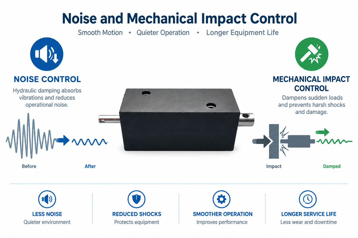
Actuation of the solenoid may cause audible clicking due to contact of the plunger with the stops at the end of the stroke.
It may be acceptable in industrial equipment but not in medical, smart home products, office equipment, or premium access control systems.
The sources of noise may be:
Plunger effect
Stop effect (mechanical)
Overclearance
Resonance of the housing
Linkage effect
High-speed switching
To minimize noise, it may be necessary to implement mechanical damping, optimize clearances, change the plunger speed, change the stops, or apply pulse control.
However, damping should not affect the bistable latching solenoid ability to achieve the final position.
Thus, there is a trade-off between noise minimization and force, speed, and reliability.
14. Environmental Conditions and Temperature Considerations
The operating environment should be defined early on.
The important conditions may be
Lowest temperature
Highest Temperature
Humidity
Dust.
Humidity
Vibrations.
Mechanical shock or/and
October 2023
Pollutants
Low temperatures may affect the properties of lubricant and mechanical friction.
High temperatures may affect the coil resistance and magnetic performance.
Dust and contaminants may limit plunger movement.
Full enclosure provides much of the environmental protection for outdoor applications.
However, the bistable latching solenoid has to be tested in conditions corresponding to the final product.
15. Customized vs. Standard Bistable Latching Solenoids
A standard actuator is often the best starting point because it can reduce the engineering time, tooling cost, and lead time for prototypes.
Nevertheless, OEM applications may require customization.
Some of the typical customization parameters are
Voltage
Resistance of coil
Strokes
Activation force
holding force
Geometry of plunger
Shaft length
Total dimensions
Dismissed
Spring
Lead wires
Connectors
16. Customization should be made for clear engineering reasons.
For instance, if the standard bistable latching solenoid meets all the requirements except the plunger length, then changing the plunger may be more economical than redesigning the magnetic structure from scratch.
Collaboration with the customer at an early stage can lead to a more efficient solution.
- Pre-production Design Validation
The engineering validation should be more than a simple functional test.
Depending on the application, the engineers may test:
Force test: Measure the force at certain points of stroke.
Holding force test: Verify the stability in both states.
Voltage test: Test at the lowest, nominal, and highest expected voltages.
Pulse test: Verify the operation over intended pulse range.
Temperature test: Test performance at environmental extremes.
Life test: Simulate long-term operation.
Vibration and shock tests: They are necessary for mobile and industrial equipment.
Noise test: It is necessary for noise-sensitive products.
Application test: Test the actuator in the end product.
A very important aspect is the test of the bistable latching solenoid in conjunction with the customer’s mechanism, since the actuator may behave differently after the installation.
17. Bistable Latching Solenoid Key Parameters in Engineering RFQ
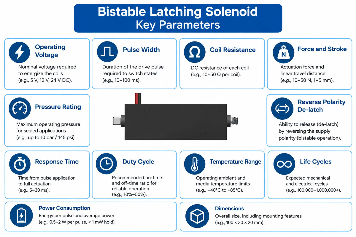
When ordering a new or customized solenoid, provide sufficient technical data to enable meaningful assessment.
Useful specifications may include:
Application: Electronic lock
Type of the solenoid: Bistable latching
Voltage: 12 VDC.
Maximum available current: 1.2A
Stroke: 5 mm
Starting force: 8N
Required grip force: 20 N
Length of pulse: 150-250 ms
Maximum frequency: 10 cycles per minute
Expected lifetime: 500,000 cycles
Operating temperature range: -20°C ~ 60°C
Maximum size: 35x25x20 mm
Low-noise requirement
Annual quantity: 100,000 pieces
More efficient engineering can be achieved by supplying CAD files, mechanism drawings, photos, and load information.
Engineering Selection Check List
Before you approve the design, make sure:
The demand on stroke is well defined.
There is enough power for the working stroke.
– Holding force is sufficient in both required states.
Voltage is compatible with the electronic system.
The driver is capable of accepting the peak current.
Pulse time is the guaranteed way to move.
Polarity control is implemented correctly.
The low-battery condition is tested.
The thermal performance is good.
Response time satisfies the system requirements.
Mechanical alignment prevents overload of side loading.
Environmental conditions are considered.
Noise is acceptable.
The operating lifetime is proven.
Production tolerance is considered.
The whole assembly is tested.
18. Summary
A bistable latching solenoid is an energy-efficient solution for applications requiring two stable mechanical positions and low holding power.
The basic engineering advantage of the bistable solenoid is simple: electrical energy is mainly used to change state, not to maintain it.
However, successful implementation of the actuator is far more than just selecting the correct voltage.
The engineers should evaluate the force throughout the stroke, holding force, pulse energy, polarity control, driver electronics, temperature, mechanical load, response time, environmental conditions, and lifetime.
Moreover, the actuator and the mechanism of the customer have to be considered as one electromechanical system.
For OEM applications, it is necessary to conduct prototype testing under realistic conditions.
The engineers should test minimum and maximum voltage, temperature extremes, mechanical load, production tolerances, and the expected operating frequency.
When properly engineered and validated, bistable technology provides reliable linear actuation with reduced power consumption and energy management.
19: Frequently Asked Questions About Bistable Latching
solenoid engineer solutions
1. What is a bistable latching solenoid?
A bistable latching solenoid is an electromagnetic actuator that has two stable states.
It can hold itself in the chosen position even after the electrical pulse is over, thus reducing or eliminating the need for continuous holding current.
2. How does a bistable latching solenoid work?
The armature, or plunger, is moved by the magnetic field generated by electric current passing through the coil.
Magnetic latching retains the chosen position after removal of power.
The actuator can be switched to the other stable state by the electrical pulse.
3. Does a bistable solenoid require constant power?
Generally speaking, the power of the coil does not have to be continuous to hold the stable position.
The main use of electrical energy is the change of the states.
Exact behavior depends on the magnetic and mechanical design of the actuator.
4. What is the difference between a bistable and an ordinary solenoid?
An ordinary spring-return solenoid usually returns to the resting position when the power is removed.
A bistable solenoid can retain itself in one of two stable positions without need of the continuous supply of power.
5. Why do you need a bistable latching solenoid for battery-powered products?
Electric energy is mainly used during state changes, which leads to reduced average power consumption in applications that remain in one position for a long time.
This is useful for smart locks, portable equipment, IoT products, and other battery-powered systems.
6. How do I select the proper solenoid force?
You should calculate the load throughout the stroke length, including springs, friction, gravity, linkage forces, and acceleration.
Then assess the actuator force vs stroke characteristics and allow for the proper engineering margin.
7. What’s the holding force of the bistable solenoid?
Holding Force – The force that retains the actuator in its latched position after removal of the coil power.
It should be considered separately from the electromagnetic force with which the plunger is moved.
8. Does a bistable latching solenoid require reverse polarity?
Many designs change the state by reversing the polarity of the current.
The details of the control depend on the magnetic and coil design.
Therefore, the driver circuit should be designed for the selected actuator.
9. What length should the electrical pulse be?
Pulse duration is a function of voltage, current, stroke length, mechanical load, coil properties, and magnetic design.
It should be long enough to reliably move the plunger under the worst case conditions without unnecessary energy consumption and overheating.
Bistable solenoids are customizable indeed.
Yes.
Parameters such as voltage, coil resistance, stroke, force, holding force, plunger geometry, dimensions, mounting, wiring, connectors, and so on can be customized depending on manufacturing capabilities and application requirements.
10. What are the typical applications of bistable latching solenoids?
Typical applications are smart locks, access control systems, industrial automation, medical equipment, electronic enclosures, metering devices, safety mechanisms, portable equipment, and other low-power electromechanical systems.
11. What tests should engineers carry out before mass production?
Engineers should check force, stroke, holding force, minimum and maximum voltages, pulse duration, temperature, lifetime, mechanical alignment, vibration, noise, and environmental performance.
The final testing should be performed with the actuator mounted in the final product.


