Latching Solenoid for Security Lock Devices
Latching DC Solenoid in Energy Efficient Systems
atching Solenoid for HVAC Control Systems
DC Latching Solenoid in Smart Home Devices
Industrial Valve Control Using Latching Solenoid
Latching Solenoid for Medical Equipment Use
Latching Solenoid for Security Lock Devices
Latching DC Solenoid in Energy Efficient Systems
atching Solenoid for HVAC Control Systems
DC Latching Solenoid in Smart Home Devices
Industrial Valve Control Using Latching Solenoid
Latching Solenoid for Medical Equipment Use

WL1037 Latching DC Solenoid for Locking Solutions

A latching DC solenoid is an electric actuator whose primary difference from ordinary solenoids is the use of permanent magnets, which create a strong magnetic field and ensure that the device retains its position regardless of power. Unlike conventional types, it doesn’t need a current flow to stay activated; instead, once moved to a particular position, it will remain stationary until another command is issued. It consists of two main states—”pushed out” and “pulled in.” Energy is consumed solely when transitioning from one state to another. As long as the position is latched, no power supply is required since the magnet retains the plunger without consuming any electricity.

Main Characteristics of Latching DC Solenoid

Two-position bistable operation: a latching DC solenoid retains its position without a power supply. Low energy consumption: A pulse of several milliseconds activates the device. Zero holding current: No constant current flow is needed to keep the device activated. High holding force: Magnetic latching ensures sufficient retention strength. Compatibility with pulse-driven circuits: Actuation from capacitors or batteries is supported.

Fail-last operation: The latching DC solenoid retains its final position in case of power failure. Options for operation: single- or dual-coil configuration depending on control requirements (reverse polarity is required for single-coil; separate windings for dual-coil solenoids). Small dimensions: High force-to-size ratio due to integral magnets.

Latching DC Solenoid Product Overview

A latching DC solenoid is an electromagnetic device that switches between two stable positions by applying DC pulses and maintaining the final state with the help of internal magnets. This type of latching DC solenoid exists in two varieties:

– Two-coil solenoid: One coil latches and the other one unlatches the device.

– Single-coil solenoid: A single coil that receives current with negative or positive polarity.

Available voltages include 3V, 5V, 12V, 24V, and 48V DC voltages.

Duty cycle range: Only intermittent pulses allowed (up to 10%).

Stroke lengths: 2 mm – 15 mm.

Force: Holding force: 50 g – 30 kg+. Actuation force varies according to the stroke length.

Solenoid enclosures: open, tubular (resistant to moisture), or enclosed (IP65/IP67 rated).

Mounting: Threaded stud mount, bracket mounting, custom mounting.

Latching DC Solenoid Product Video

Latching DC Solenoid Detail Dispaly

Latching DC Solenoid Technical Data Sheet

Brand Weilong Technology Model Number WL1037
Rated Voltage (V) DC 24.0V Rated Power (W) 12.3 W
Work Model Push-Pull Type Holding Force (N)  2.6 N
Stroke (mm) 10 MM Customized Reset Time(s) 0.2
Service Life 500 Thousand Times Certification CE, RoHS, ISO9001,
Material Superior Magnet Iron Lead Wire Length (mm) 200 MM
Install Style Screw Tolerance of Dimension  +/-  0.1 MM
Water-proof  None Insulation Class B
Hi-Pot Test AC 600V 50/60Hz 2s Non-excitation Holding Force 0
Working Temperature -10°C-100°C Duty Cycle 1-100%
Thread Depth (mm) / Payment Term TT, or LC At Sight
Sample Order Yes Warranty 1 Year
MOQ 1000 pcs Supply Ability 5000 pcs per Week
Delivery Time 30 Days Port of Loading shenzhen

Latching DC Solenoid Mechanism

A latching DC solenoid works on a principle of creating two different fields—one provided by the coils and another by a permanent magnet installed inside. When a short DC pulse is applied, the first magnetic field takes over the permanent magnet’s field, moving the plunger to the other side and putting it in its final position. Once the plunger moves into its final position, the magnetic flux path changes and forms a closed loop with the magnet, keeping the solenoid in this position without requiring a continued power supply to the coil. A short pulse with an opposite polarity allows reversing the magnetic field and moving the plunger back to its original position. The whole process only takes several milliseconds, after which a latching solenoid holds its state without requiring any power.

What is the difference between push-pull and a latching DC solenoid?

The difference between these two solenoids lies in power consumption, control, and application. An engineering comparison of both will be presented below.

⚙️ Conceptual Difference

DC Push-Pull Solenoid

Power remains applied throughout; movement is achieved
Returns to initial position upon disconnection of power (springs/gravity)
Keeps no memory of position

 Latching  DC Solenoid

Maintains position due to presence of permanent magnets
Switches from one position to another through use of short pulses
🔋 Keeps memory of its last position upon disconnection of power. 🔋 Power Consumption
Needs continuous power to keep moving → Consumes more energy
Uses pulses and, hence, consumes less energy. 👉 The key operational difference.

🔄 Operation

Push-pull solenoid operation

Application of power causes coil to create a magnetic field that pulls plunger inside
Disconnection of power allows spring to push it out

Latching DC Solenoid operation

Pulse 1 causes the plunger to move and lock using permanent magnets
Pulse 2 causes plunger to be released/repositioned by changing polarity of the current.

🌡️ Heat production

Push-Pull creates heat continuously when powered (DC current)
Latching produces limited heat (short pulses) grip force.
Push-Pull has grip force depending on current
Latching has force maintained by permanent magnets without any power ⚡ control requirement.
Push-Pull has simple requirement of DC power supply
Latching requires controlled pulses or H bridge for polarity reversal. 🧩 Applications of Each Type

Push-Pull Solenoid

Industrial automation
Actuators and Valves
Sorting methods

Latching DC Solenoid

Smart Locks
Devices running on batteries
Vending Machines
Energy-saving devices
⏱️ Reliability & lifetime Push-Pull: More heat production → possible wear over time
Latching: Little heat produced → increased life-span


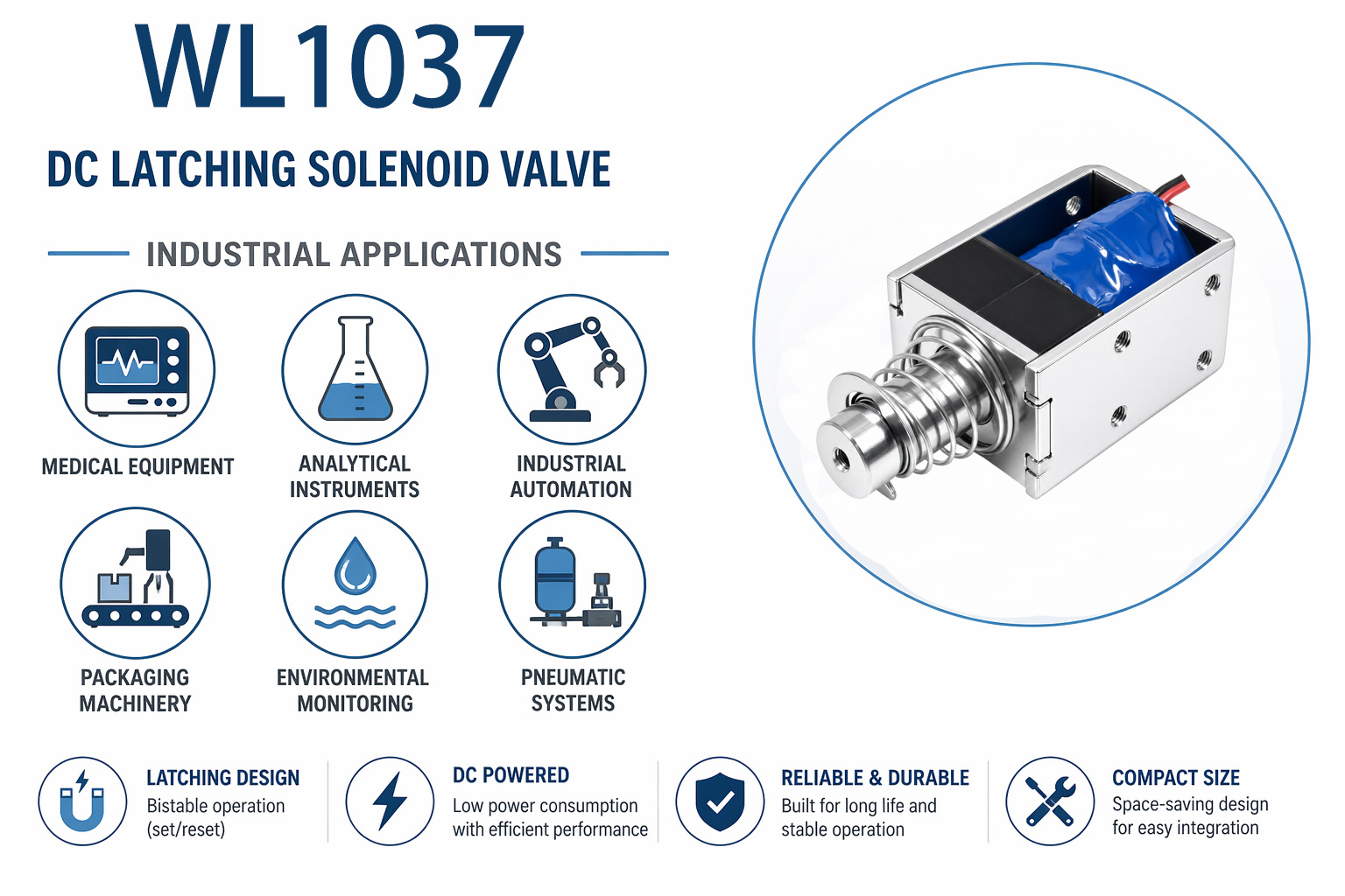
Latching DC Solenoid Industrial Application

WL1037 Latching DC Solenoid Industrial application

Battery-operated or energy-conserving devices can benefit from employing a latching DC solenoid in their design. For instance, in smart meters and gas/water shut-off valves, such solenoids allow opening the valve temporarily and then latching to maintain this state. They work excellently as components of electronic deadbolts and locks, as they don’t draw power when latched, providing secure locking operation without excessive wear. In battery disconnect switches, latching solenoids keep the connection established between battery packs. For automobiles, a latching solenoid serves as an ideal component in battery pack contactors and electric parking brakes, keeping the brake engaged in case of a power outage.

Portable medical devices such as infusion pumps and oxygen concentrators use them as battery-life extenders by maintaining a mechanical latched state without power consumption. Industrial automation includes latching solenoids as sensors’ actuation elements for controlling dampers, diverters, and pneumatic pilot valves since continuous power supply is impractical in some settings. Agricultural machinery also makes extensive use of latching solenoids to activate battery-operated equipment like fence gates and irrigation timers powered by solar chargeable batteries. Consumer electronics such as robot vacuum cleaners and smart gas shut-off solenoids benefit from latching operation. A latching DC solenoid ensures fail-last protection and are preferable over spring-return ones in applications like fire dampers, where a device stays in its last commanded position in case of complete power loss, which may prove crucial. Due to a lack of heat generation, they work well in ATEX-rated equipment.

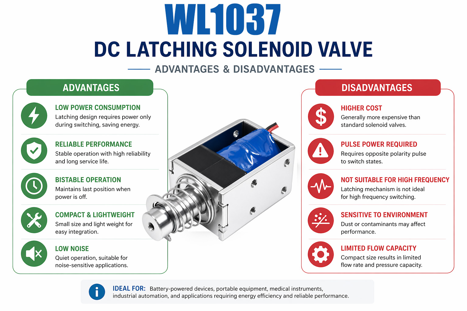
Advantages and Disadvantages of Latching DC Solenoid

Latching DC Solenoid: Advantages and Disadvantages

Advantages of Latching DC Solenoid

– Very low power consumption: Makes it optimal for battery-powered and remote installations.

– No heat emission when idle: Ensures coil longevity without any cooling arrangements.

– Fail-last operation: Keeps the last commanded position during a power failure (useful for shut-off devices).

– Longer operational life: Lower duty cycle rate increases lifespan and durability.

– Space-saving holding force: Provides high retention force while being compact.

Disadvantages of Latching DC Solenoid

– Requires pulse with bipolar polarity: Single-coil configuration necessitates an H-bridge to operate correctly.

– No fail-safe option: The spring return mechanism cannot be used, and the solenoid remains latched after a power loss.

– Pulse duration sensitivity: Too-short pulses cannot open the latching mechanism, while too-long ones can cause coil heating (rare occurrence).

– Higher price than ordinary solenoids: Integration of magnets and precision assembly lead to increased costs.

– Increased likelihood of magnetic contamination: Ferrous debris can interfere with the operation of magnets.

– Uncertainty upon power recovery: Position-sensing method must be implemented (limit switch or hall sensor).

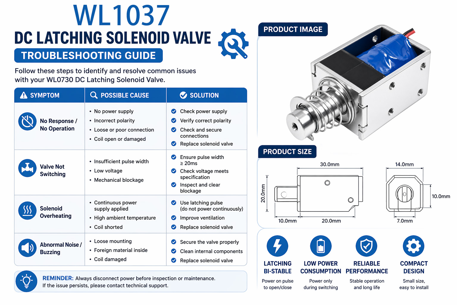
Latching DC Solenoid Troubleshooting Guide

WL1037 Ltaching DC Solenoid Troubleshooting

As latching DC solenoids hold their position without consuming any power, the failure in this type of electromagnetic device relates to electrical problems, mechanical malfunctions, or installation errors. Below is a comprehensive troubleshooting guide covering the most common issues.

1, Preliminary Steps

– Safety first: Switch off the power supply; de-energize solenoid (apply LOTO).

– Visual diagnostics:

Check for burnt/damaged coil insulation, melted insulation, frayed wires, or damaged/burnt terminals.

Check physical damage to the device and bore for any debris or dirt.

Look for polarity markings on the terminals.

2. Electrical Troubleshooting (Most frequent faults)

2.1 Power Supply and Pulse Checking

– Fault symptoms: No actuation, weak pull-in force, or inability to latch/unlatch.

– Check for:

1) Input voltage at terminals (should match the operating voltage, e.g., 12V or 24V, ±10%).

2) Proper pulse duration (should not exceed 500 ms). Constant power will damage the coil.

3) Blown fuse, tripped breaker, malfunctioning relay, or broken wires (conduct continuity test).

4) Insufficient output voltage from the power supply (voltage drops by >10%).

2.2 Coil Diagnostic Test (Open/short circuit)

– Faults: Cold/warm coil, no magnetic field or burnt smell.

– Coil testing (Ohm-meter readings):

– Open: Resistance = ∞ (coil wire broken). Replacement needed.

– Shorted: Resistance ≈ 0 (coil windings are shorted). Replacement needed.

– Abnormal resistance: Difference from specification exceeds ±20% (e.g., 10Ω).

– Coil insulation test: Megohmeter reading > 100MΩ DC voltage is satisfactory; otherwise, replacement is recommended.

2.3 Polarity Test/Control Circuit

– Latching DC solenoids must receive proper polarities for proper operation.

– Incorrect polarity does not generate any actuation forces. Switch the wires’ polarity.

– Test control circuit for proper pulses’ voltage and timing (PLC output or switch signals).

3. Mechanical Troubleshooting (Faults related to device wear)

3.1 Plunger/armature binding

– Faults: Squeaking sounds, inability to activate or bind.

– Possible causes: Dust or dirt particles, misalignment, wear, rust formation, or insufficient lubrication.

– Solution:

– Clean the plunger bore with alcohol or other cleaning solution; dry with compressed air.

– Lubricate with a dry film lubricant (silicone-based). Don’t use oily lubrication to avoid dust attraction.

– Remove any burrs or scratches from the plunger surface; replace a worn-out plunger.

– Verify correct mounting alignment; repair/replace bent mounting brackets.

3.2 Permanent magnet failure

– Faults: Low/lack of holding force; drift/erratic latching/unlatching; or insufficient pull-in force.

– Likely causes: Heat demagnetization or damage to the magnet.

– Diagnosis:

– Manual checking: The plunger must hold steady in the end position without power application.

– Compare the magnet’s pull-in force with the manufacturer’s recommendations and specifications.

3.3 Spring problem or improper return spring mechanism

– Possible faults: Lack of return mechanism, partial travel distance, or armature binding.

– Causes: Broken spring, improper spring alignment, or wear.

– Fixes: Inspect the spring for damages; replace if it’s not elastic enough.

3.4 Excessive air gap and misalignment

– Problem: Decreased magnet force (air gap > 0.1 mm).

– Solution: Check the air gap with a micrometer and align plunger if necessary.

4. Latching-Specific Failures (Set/Reset Issues)

Failure Mode Symptoms Root Cause Fix
Fails to Latch (Set) No hold after pulse Undervoltage, wrong polarity, weak pulse, coil open, plunger bind, magnet weak Correct power/polarity, clean plunger, replace coil/magnet
Fails to Unlatch (Reset) Stuck in a latch Reverse pulse missing/weak, plunger bind, spring broken, magnet stuck Verify reset pulse, free the plunger, and replace the spring.
Intermittent Latching Random hold/release Loose wiring, dirty contacts, EMI interference, weak magnet Tighten connections, shield cables, clean contacts
Weak Holding Force Drifts under load Magnet demagnetized, air gap too big, plunger wear Replace the solenoid and adjust air gap


FAQs Of Latching DC Solenoid

1) Is it possible to use a latching solenoid permanently?

No, you can use a latching device only when applying a short pulse (in milliseconds). Applying a constant current will overheat the coil and damage it.

2) What happens if you remove the power when the device is latched?

It keeps its last position (fail-last). In order to operate in a fail-safe mode, you need an additional spring for return.

3) Is a dedicated controller needed?

A latching solenoid is not controlled with just a relay or push-button; you need an H-bridge (for a single-coil design) or two transistor drives (for dual coil).

4) How long should a drive pulse be applied?

For most latching solenoids, a beneficial value is 50 to 150 ms depending on the load and voltage. Very short pulses may lack force while very long pulses will waste energy and heat up.

5) Are they applicable for battery-powered devices?

Certainly. Zero holding current makes them especially useful in battery- or solar-powered applications like smart meters, locks, etc.

6) Can I know whether the device is latched or unlatched?

The device does not provide any indication of being in one of these states. You can add an external limit switch or a Hall sensor. Some controllers are able to detect the last polarity of the pulse.

7) Do other magnets affect the device?

Strong external magnets will change the magnetic circuit and may reduce the force, preventing the solenoid from locking or unlocking. Avoid putting magnetic tools near the device and loudspeakers.


8) Can I manually override the latching device?

Some solenoids are equipped with a built-in push button or screw on the back of the device. Others allow for a careful movement of the plunger by hand using a non-magnetic tool.

Tips for Choosing a Latching DC Solenoid

Choosing a latching DC solenoid is selecting an appropriate interaction between electrical, mechanical, and environmental factors. Here is a guide that will help you choose your device.

1) Actuation Requirements: Stroke and Force

– Stroke (mm): Find out the stroke length of your plunger in the actuated position; for example, the distance to move a valve pin is approximately 5 mm.

– Holding force (N or kg): This is the external load that the device will have to hold, for example, spring back-pressure, fluid pressure, or friction. Latching solenoids are powerful holding devices, but they produce a weaker actuation force during a pulse. Refer to the force versus stroke chart from the data sheet.

2) Drive Capability

– Coil voltage: Choose the voltage compatible with your power source. Commonly used coils have voltages of 12 V DC or 24 V DC.

– Single coil or dual coil: Select a single coil solenoid if you can drive the device using an H-bridge. Otherwise, go with a dual-coil device if you can generate two independent pulses. Consult your battery or capacitor specifications to make sure that it can provide enough current during a pulse (for example, 1.5 A at 12 V for 80 ms). If your drive is too weak, the solenoid won’t manage to latch.

3) Duty Cycle of Latching DC Solenoid

Latching solenoids consume no current when holding; therefore, the duty cycle is defined as the pulse duration divided by the cycle time. Typical values are 5–10%, for example, 100 ms every 2 seconds. Pulsing the solenoid too often will lead to excessive heat.

4) Environment Conditions

– Temperature: The magnetic field is degraded above the 150 °C; there are solenoids working below -40 °C.

– Enclosure type: If you plan to use the device outdoors or in industrial conditions, choose an IP65 enclosure or a tubular solenoid with a shaft seal.

– Corrosion: Stainless steel plunger and housing will be needed in salty environments.

5) Feedback and Safety Features

– Fail-last vs. fail-safe: Latching solenoids do not allow fail-safe operation. Spring return solenoids return to their initial position when the current stops.

– Position sensing: In case you want your controller to be aware of the position after the device was turned off for an extended period of time, use a limit switch or a Hall effect sensor, or simply add control capabilities into the controller to recognize the polarity of the last pulse.

6) Size and Mounting

– Envelope size (diameter, length, mounting pattern): Make sure that the dimensions match those of your mounting area. Tubular solenoids fit narrower bore sizes than open-frame types, which usually cost less per unit when prototyping.

– Always check the operation of the selected solenoid together with your real load and power source. The pulse duration should be carefully optimized; it is not recommended to use pulses shorter or much longer than necessary.


Get A Free Quote Now

Contact Form

Related Products

Related News

Scroll to Top

Get A Free Quote Now !

Contact Form
If you have any questions, please do not hesitate to contact us.
Weilong Solenoid Company Culture
