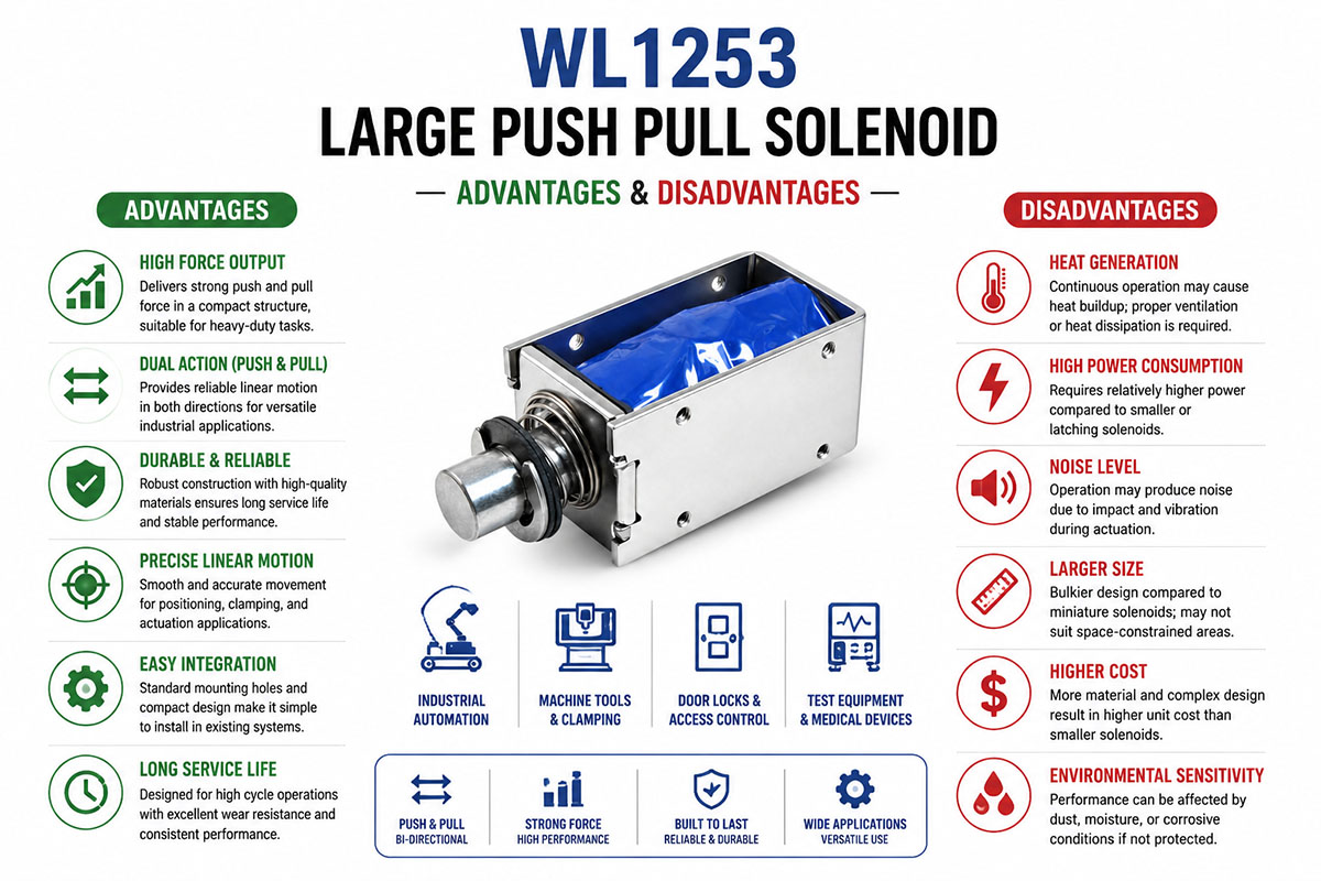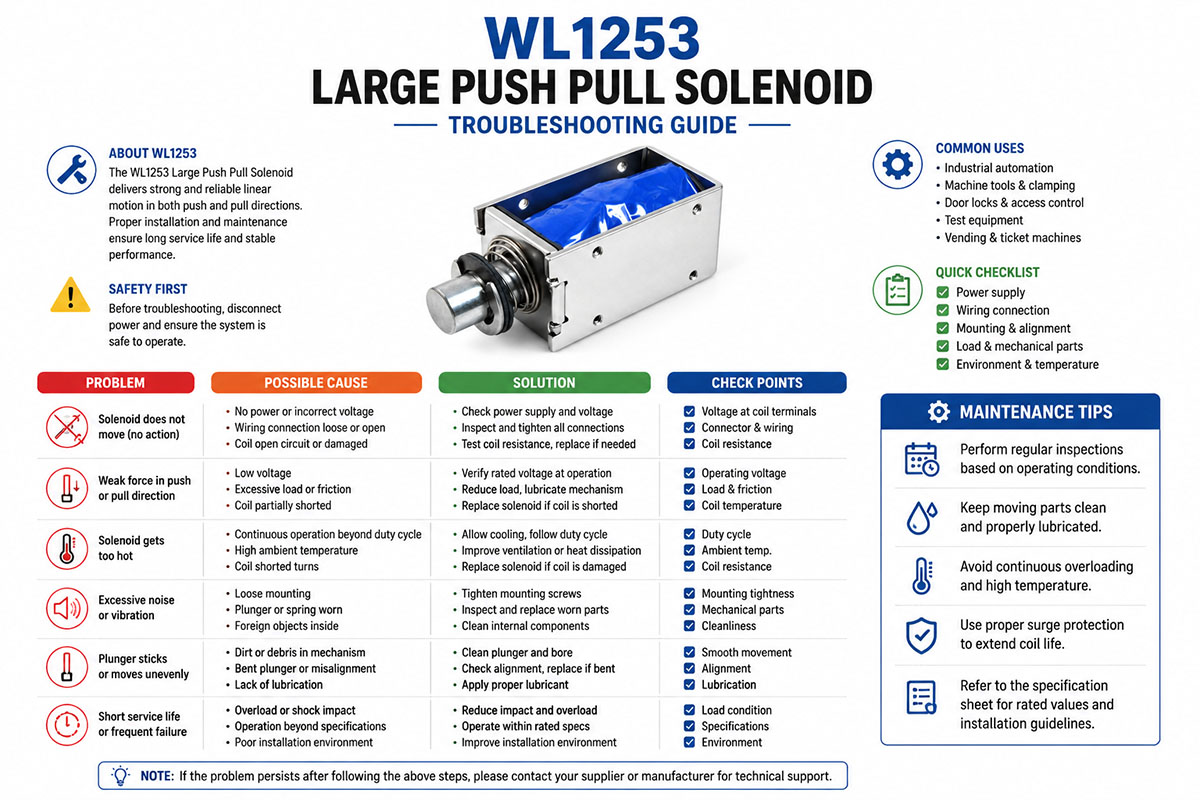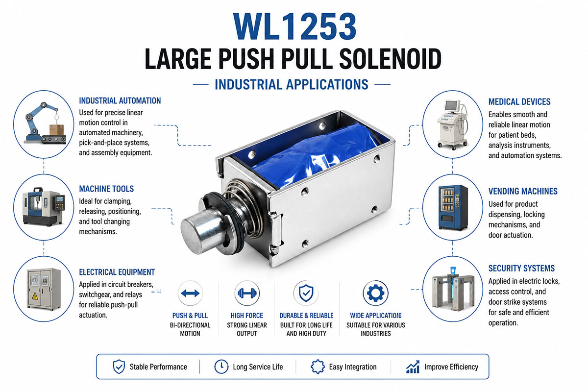
The large push pull solenoid is widely used in industrial applications, where powerful and reliable linear motion is required.
In industrial automation they control mechanical motions, such as clamping, positioning, locking, and release operations. Large push-pull solenoids are used in automated assembly machines due to their precise movements and quick response.
These solenoids are also used in machine tools for fixture control, tool change systems, and mechanical positioning devices. They can generate high forces and can be incorporated into heavy duty industrial equipment
They are used in electric locks, access control devices, and door mechanisms in security systems. They provide reliable locking and unlocking operations.
Large push-pull solenoids are also being applied in medical devices for adjustable mechanisms, movement control, and positioning systems, where precision and reliability are critical.
Other applications are vending machines, industrial testing equipment, electrical cabinets, transport equipment, and special automation systems.
Due to their high force output, compact design, and easy electrical control, large push-pull solenoids are increasingly used as replacements for traditional mechanical actuators in modern industries.
How to calculate the large push-pull solenoid force for your automation project need
Large Push Pull Solenoid Force Calculation for Your Automation Projects
One of the crucial tasks in designing an automation system is determining the appropriate force for your large push-pull solenoid. If the solenoid is undersized, it won’t move the load. Oversizing the solenoid would increase its cost, power consumption, and installation area. Proper force calculation is necessary for reliability, increased service life, and efficient performance.
1. Understand Solenoid Force
Solenoid force depends on the total load force, which needs to be moved. The equation is as follows:
Required Solenoid Force = Load Force x Safety Factor
Typical safety factor:
For light-duty automation: 1.2 – 1.5
Industrial applications 1.5-2
In case of heavy vibration and impacts: 2-3
For instance:
For your automation mechanism, if the mechanical load force is
50 N
Safety factor to be used:
2.0
Solenoid force needed:
50N + 50N = 100N
You need to choose a solenoid with a fat leastess than 100N.
2. Determine Load Force
Load force includes the following:
2.1 Gravity Force
In case of vertical movement:
F = m * g
Where:
F = Force (N)
m = Mass in motion (kg)
g = acceleration due to gravity (9.8 m/s²)
For instance:
If the moving mass is:
5 kg
Gravity:
5 * 9.8 = 49N
This load requires more than 49N of force to be lifted.
2.2 Friction Force
For sliding mechanisms:
F = μN
Where:
μ = coefficient of friction
N = force normal
For example:
For mobile platform:
Loading: 100N
Coefficient of friction:
0.2
Force of Friction:
100 × 0.2 = 20N
2.3 Spring Force
Most push-pull solenoids operate against a return spring.
Spring force.
F = kx
Where?
k = spring rate (N/mm)
x = compression distance (mm)
For instance:
Spring rate:
5 N/mm
Compression:
10 mm
Spring force:
5 * 10 = 50N
3. Determine Solenoid force at different stroke positions
Important point in solenoid design:
The solenoid force varies along the stroke.
Generally speaking:
The maximum force is in the end position.
A large air gap decreases force.
The starting force is less than holding force
For example:
A large push-pull solenoid might have the following:
Stroke Position Force
0 mm – 150 N
5 mm – 100 N
10 mm – 60 N
15 mm – 30 N
Please pay attention to the force vs. stroke graph in solenoid specifications.
4. Determine Required Holding Force
In cases of:
Electric locks
Clamping devices
Position holding mechanism
It is the holding force that counts.
Calculation:
Holding Force > Static Load x Safety Factor
For example:
Required clamping force:
80N
Safety factor:
1.5
Holding force needed:
1.5 * 80 = 120N
Select a solenoid able to hold more than 120N.
5. Consider Duty Cycle and Heating
The coil temperature affects the force of large push-pull solenoids.
Greater force usually requires the following:
More turns of coil
Increased current
Greater power consumption
Continuous operation check:
Duty cycle formula:
Duty Cycle=ON Time/(ON Time+OFF Time)*100
For instance:
Solenoid ON:
5 sec
OFF:
20 secs
Duty cycle:
5 ÷ (5+20) × 100 = duty cycle 20 %
A 20% duty cycle solenoid cannot replace a 100% duty cycle one always.
6. Separate Push Force from Pull Force
Large push-pull solenoids have different
Force applied
Traction force
Because of changes in the magnetic circuit.
For example:
Solenoid specifications:
Pull force: 150 N
Thrust force: 80 N
If your device requires 120a push force of 120 N, this model will not fit, even withhigh pull force.
7. Example Calculation for Automation Equipment
Use:
Automatic locking system
Minimal requirements:
Load moving: 8 kg
Horizontal movement
Friction coefficient: .15
Spring force: 30 N
Safety factor: 2
Step 1: Determine friction
Support force:
8 kg * 9.8 = 78.4 N
Friction;
78.4 x 0.15 = 11.8N
Step 2. Add spring force.
Load:
1
11.8N + 30N = 41.8N
Step 3. Safety factor application
41.8 × 2 = 83.6 N
Recommended Solenoid:
≥100N Large Push-Pull Solenoid
8. Large Push-Pull Solenoid Selection: Parameters To Be Checked
Engineers should verify the following before choosing a model:
✅ Push force required (N)
✅ Pull force required (N)
Stroke distance (mm) ✅
✅ Operating voltage (12 VDC / 24 VDC / 48 VDC)
✅ Duty cycle (%)
✅ Frequency of operations
✅ Size of installation
✅ Operating temperature
✅ Connection way
9. Common Design Errors in Solenoid Force Calculation
9.1 Estimating the force by load weight only
Real force includes friction, spring force, and safety factor.
9.2 Ignoring stroke length
While a solenoid has a high holding force, it may have insufficient starting force.
9.3 Use of maximum force value
Always check the force at the required stroke length.
9.4 Duty cycle is ignored
Running a high-force solenoid for a long period makes it hot.
9.5 No consideration of push-pull discrepancy
Always be cautious and check both forces.
Conclusion
To determine the proper solenoid force, you need to analyze the whole mechanical system. Load weight, friction, spring force, stroke distance, and duty cycle are to be taken into account. When designing industrial automation systems, using a solenoid with an appropriate force margin and duty rating provides reliable movement, increased service life, and machine efficiency.