 Chapter 1 : Inductor Coil Design Introduction
High-performance of inductor coil design is one of the important parts of contemporary engineering. Inductor coils are widely applied in modern electronic and electric equipment for energy storage, electromagnetic conversion, filtering, signal processing, and similar tasks. You can find inductor coil design in various systems from power electronics and automotive applications to medical devices and industrial automation.
However, high-performance inductor coil design is far from being simple. There are many aspects that should be taken into account to create high-quality, reliable inductor coils – materials, electrical parameters, thermal features, mechanical constraints, specific requirements, etc. With proper engineering services you will be able to create inductors that will help to optimize system efficiency and minimize energy loss.
Chapter 2 : What Is Inductor Coil Design?
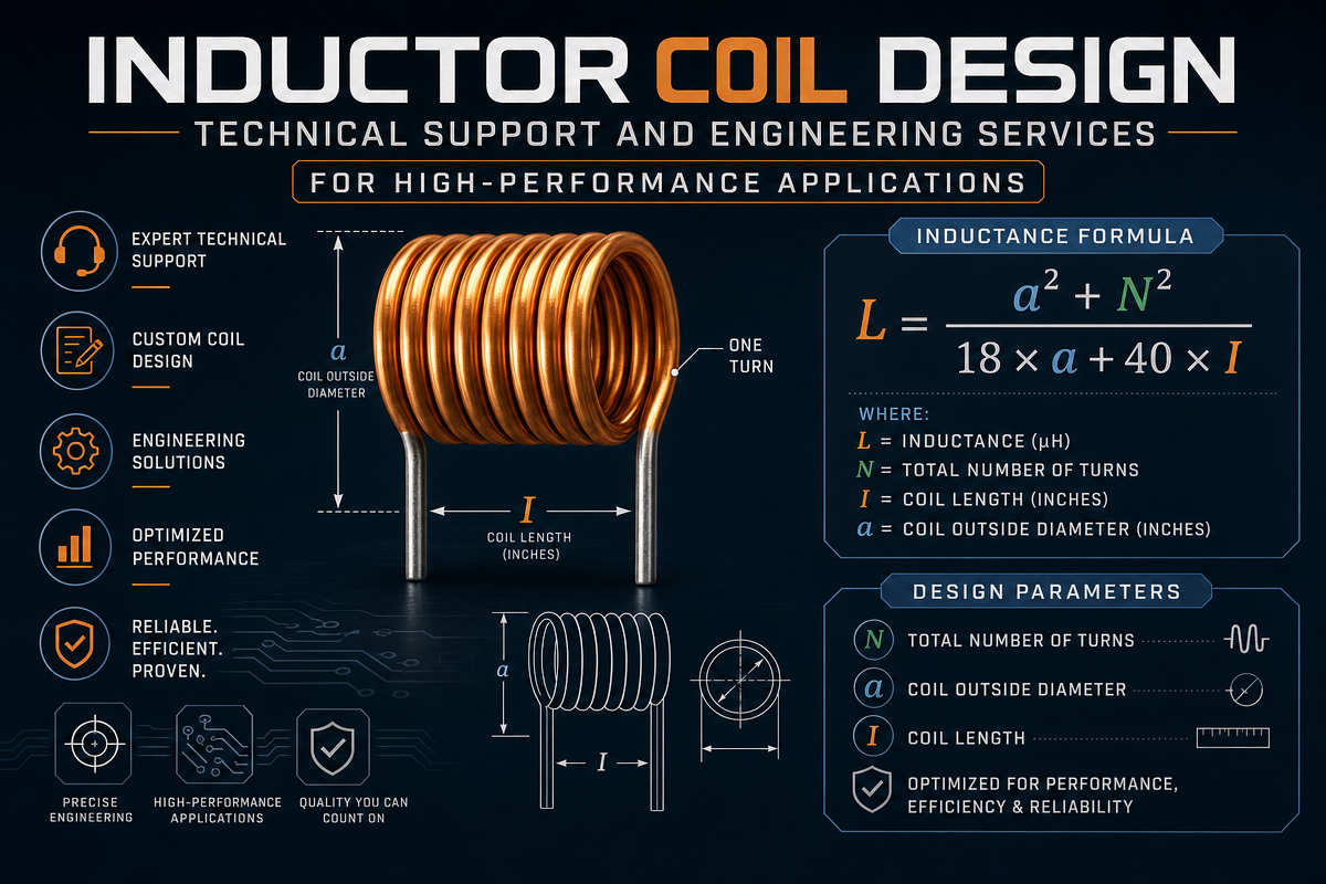
Inductor coil design means engineering process of creation of magnetic components for storing energy in a magnetic field due to electrical current passing through a coil. Inductor performance depends on multiple parameters, for example:
Inductance value (Henry)
Core material type (ferrite, powdered iron, air core, etc.)
Winding configuration and wire gauge
DC resistance
Saturation current
Temperature change and thermal stability
Physical parameters and packaging
A properly designed inductor coil takes into account all these factors to achieve required electrical performance with minimal losses.
Chapter 3 :Importance of Professional Inductor Coil Design
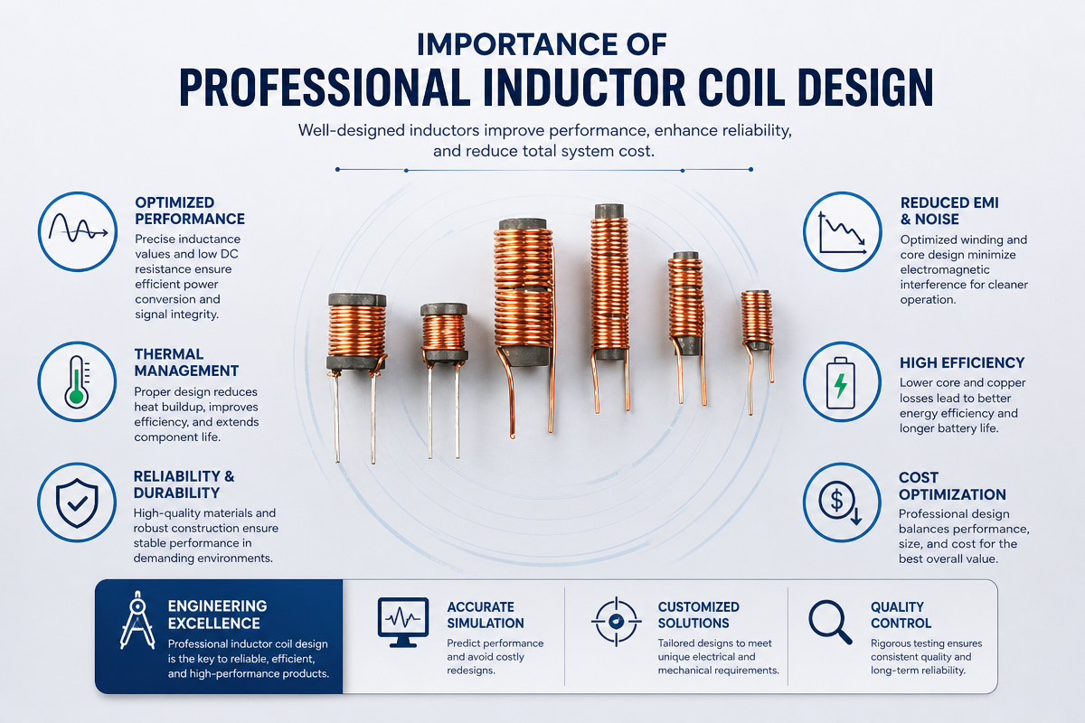
In many cases, inductor is an integral part of some complex system. For example, inductors can be applied in power supplies, converters, filters, electromechanical actuators, and other complex constructions. Poor design of inductors can cause such problems as:
Generation of excessive heat
Loss of energy and poor efficiency
EMI-related problems
Premature failures of components
System instability
Proper design of inductor coils allows eliminating these risks with the help of modeling, prototype testing, and other professional techniques.
Engineering services are especially important in case of complex high-frequency, high-current, and compact inductor coils with strict tolerances and performance requirements.
Key Parameters in Inductor Coil Design
3.1 Inductance value
Inductance shows how much energy can be stored in a coil. Inductance should be properly estimated according to the requirements of application, such as frequency and conditions of loading.
3.2 Core material
Magnetic core greatly influences performance:
Ferrite core – high-frequency operation, low losses
Powdered iron core – better saturation
Air core – no saturation, but smaller inductance
Choosing appropriate core material is one of the key steps in design of inductor coil.
3.3 Wire type and gauge
Choice of copper wire impacts performance of inductors – resistance and ability to carry electrical current. In many cases litz wire is applied for high-frequency coils to reduce the impact of the skin effect.
3.4 DC resistance
Lower DC resistance improves efficiency, but increases size and cost. Engineer should make compromise here.
3.5 Saturation current
Saturation current is the current value after which inductance starts decreasing drastically. This parameter is very important for inductors in power applications.
3.6 Thermal management
Influence of heat generation should be considered because it impacts insulation and reduces life span.
Chapter 4 : Engineering process of Inductor coil design
Professional engineering process is the way to get reliable results. In general, there are following stages of engineering work:
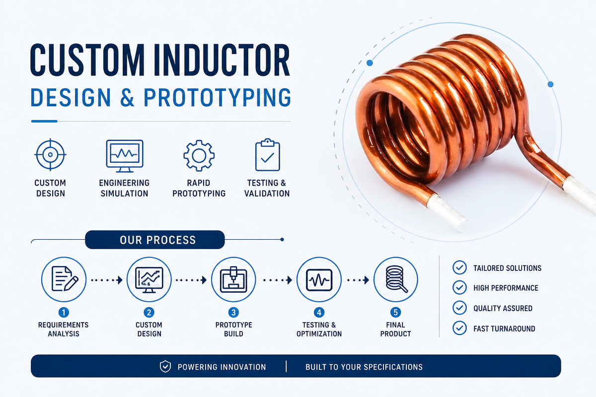
4.1 Requirement analysis
First, engineers estimate the requirements of the application, for example, voltage, current, frequency, environmental conditions.
4.2 Simulation and modeling
Special software for simulation of electromagnetic processes is used for estimation of performance of future inductors. This step helps to eliminate the risk and save money on prototyping.
4.3 Material selection
Selection of the best core and wire materials based on the results of modeling.
4.4 Prototype development
Development of the first samples of inductors for testing. This step validates calculations made theoretically.
4.5 Testing and validation
Tests can include:
inductance precision testing
temperature rise testing
saturation current verification
EMI performance analysis
4.6 Optimization
Making changes in design according to the results of tests and achieving of final parameters.
Mass production support
Support of consistent quality of mass production with implementation of proper standards and process control.
Technical support in inductor coil design
Professional engineering services provide not only design of inductor coils, but also technical support at all stages of development of inductors.
Chapter 5 : Custom Inductor coil Design & Prototyping
5.1 Application-Specific Designs
Power conversion (DC-DC, AC-DC), EMI filtering, RF/matching networks
Core material selection: ferrite, iron powder, amorphous/nanocrystalline,
Winding Design: Litz Wire, Foil, Strip, Multilayer and Planar Winding Optimization
Thermal Management: Loss Modeling, Thermal Simulation, and Integrated Cooling
5.2. Magnetic Analysis and Modeling
Finite Element Analysis (FEA): Three-Dimensional Electromagnetic Field Simulation
Predictions regarding loss:
Core loss: Steinmetz parameter
Winding loss: Skin effect/Pro
Saturation Analysis: DC Bias Properties and Nonlinear Modeling
Electromagnetic Intference Prediction:Stray Field Modelling and Shielding Effectiveness
5.3. Performance Verification and Testing
Measurement of parameters: L, DCR, Q, SRF, Isat
Environmental testing: Thermal Cycling, Humidity, Vibration
Reliability Tests: Accelerated Life Test, Insulation Breakdown Test
Application Testing: In-Circuit Performance Verification
================================
Chapter 6 : Technical Support Level
6.1: Design Consulting
For Engineers Who Need Help in the Following Areas:
Inductor Selection for Various Topologies (Buck, Boost, Flyback, LLC)
Trade-offs between frequency/power requirement for core material
Electromagnetic interference layout considerations
Fixing problems in the current design (noise, saturation, overheating
Requirements: Design review, component recommendation, application description
Second level: Custom Design & Development
In the case where the following conditions:
Unusual inductance value or size</asp
6.2 Extreme environment conditions (-55°C to 200°C and above)
High frequency/high power density missions
Regulatory Compliance (AEC-Q200, Medical
Deliverables: Complete Design, Sample of Prototype, Test Report
For patient care that requires higher support levels than those
In complex systems where the following conditions apply:
Magnetic Module Design (Integrated Transformer/Inductor
6.3 Multiphysics simulation
Product production tools and processes
Quality Control & Test Fixture Development Deliverables:A Complete Solution, Manuf. Docs.,Support.
Common Design Challenges We Address
Power conversion applications:
Challenge: Packing a lot of current into a small space
Our Solution:Designação do Indutor Multiphasado
Chapter 7 : Advanced Integrated Cooling (Embedded Heat Pipes, Thermal Interface Materials)
Low-loss magnetic core materials (Low Bs, high Curie temperature)
For example: 500A, 100kHz inductor in less than 50 cm³.
Challenge: Handling a large input voltage range (for example, 4:1).
Variable inductor design
Multigap optimization of linear saturation characteristics
Coupled Inductor Design for Multi-Output Converters
RF and High-Frequency Apps
Challenge: Maintaining a high Q value in the VHF/UHF range.
Chapter 8 : Our solution to Inductor coil design
Inductor coil design according to our method involves the use of electromagnetics simulations combined with material science for creation of an effective and highly-efficient solution that would fit specific applications. We always take care about accuracy and use multiphysics modeling to investigate core geometry, winding configuration and parasitic factors including AC resistance and stray capacitance.
8.1 Key Capabilities:
Individual Geometries: Besides traditional solenoid structures, our specialists can develop planar, toroidal and even 3D-printed coils.
8.2 Material Choice:
Choosing of the right core (ferrite, powdered iron or amorphous alloys) and proper conductor (Litz wire, foil or traces).
8.3 Cooling Solutions:
Implementation of the cooling system in the structure of the coil.
Using iterative prototyping and real-time impedance testing allows us to cut development time drastically while still meeting performance parameters of inductance tolerance (±2%) and Q-factors.
Our solution can be applied in various industries from power converters and EMI filtering solutions to wireless charging systems and automotive industry with powerful inductors.
At the end, we deliver an electromagnetic subsystem along with full test data.
Chapter 9: Challenge: High-power radio frequency (>1kW )
9.1 Our strategy:
The design of a water-cooled winding is an important consideration in high voltage insulation systems, especially in situations where arc prevention is necessary, like in high-impedance systems.
Professional applications include a variety of fields. In the medical sector, in the areas of Magnetic Resonance Imaging as well as radiofrequency ablation, the variety of materials utilized includes those that are non-magnetic, such as aluminum-wound transformers and ceramic-core components. Additionally, there are requirements for biocompatibility of packing materials and isolation in high-voltage circuits.
For vehicles like electric and hybrid cars, it is necessary to meet AEC-Q200 Class 1/0 requirements that are tested in conditions ranging from -40°C to 150°C. The other important criterion is that of vibration-resistant mechanics and partial discharge testing in systems that operate above 800V.
The MIL-PRF 27 specification is required for use in military applications, and radiation hardening is a basic design requirement.
Operation in extreme temperatures from -65°C to 200°C is another crucial point.
Tools and design methodologies are necessary to accomplish the above-stated objectives. Software and simulations are important, such as finite element analysis software like ANSYS Maxwell, JMAG, and COMSOL Multiphysics. Circuit simulation software, with a SPICE model and nonlinear properties, is also used. The simulation of thermal analysis is performed using the computational fluid dynamics (CFD) method.
9.2 Proprietary Tools:
In-house design automation software
Process Design
Requirements analysis: Electrical, mechanical, environmental, and cost factors.
Conceptual Design: Identifying 3-5 solution alternatives and trade-offs
Supports: Provides support for designing devices with complex architectures. Involves:
Prototyping: Rapid Prototyping (Generally takes 1-2 weeks
Verification: Electrical, environmental, and reliability testing
Deliverables: Design plan, manufacturing drawings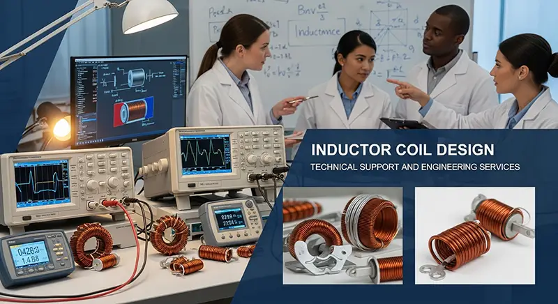
Chapter 10 : Materials professional knowledge
Key materials
Ferrite: MnZn (1 kHz)
Powdered core materials: iron powder, iron, moly permalloy (M
These laminated materials are:
* Silicon steel
* Areas of Expertise: Throughput, Kool Mµ
* Conductor options:
- Solid metal wire: Round, Rectangular, Foil
- Liz Line: Designed for specific frequencies.
Chapter 11 : Specialized applications: Copper-clad aluminum and silver-plated copper.
Cooling: Cooling is facilitated using hollow conductors.
Encapsulation And Insulation
The potting materials are:
- Epoxy resin, silicone, polyure
- Bollard applications involve the use of high temperature plastics like PPS and LCP.
- Insulating Materials
- Insulating materials include polyimide, Nomex, poly
Chapter 12 : Engineering Support: Frequently Asked Questions
Q 1 : What is the initial information required in a custom design?
A: The Essentials:
Electrical parameters (L, Isat, IRMS, frequency,
Environmental factors (temperature, humidity, vibration)
Size Restrictions and Installation Techniques
Regulations & Compliance Requirements
Preferred quantity and budget
Q 2 : Hot long does the Prototype development usually takes ?
Design phase: 1 to 3 weeks, depending on complexity.
Prototyping typically takes 2
Testing/Validation: 1 to 2 weeks
However, there is an option for expedited shipping, but with an additional fee.
Q3: Are SPICE models or behavioral models available?
A: Yes, we offer:
Linear Models
(L, R, C equivalent circuits)
Nonlinear models (saturation, h
Loss Models (Frequency/temperature dependent)
Supports: SPICE, Verilog-A, and other propriety formats for
Q4 : Can you help with heat transfer?
A: We offer complete heating services:
Loss modeling and predicting heat generation
Thermal interface materials:
Forced Air Cooling/Liquid Cooling Integration
Prevention of thermal runaway
Q5: What help do you provide the manufacturing industry?
A: We offer complete production transformation:
Process documents and work instructions
Test fixture development & programming
Quality control plan development
Failure Analysis/Improve Yield
Failure Analysis:
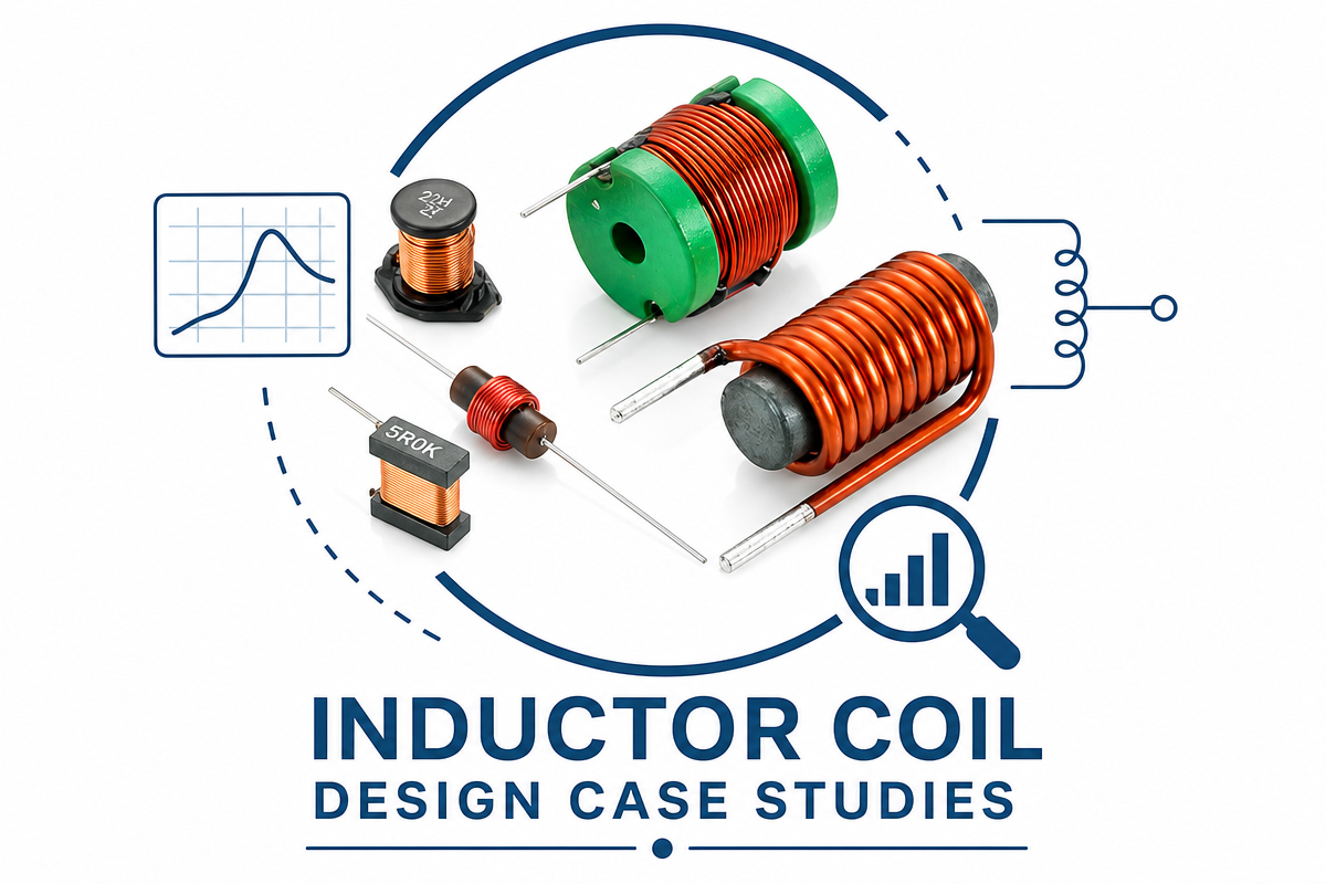
Chapter 13: Inductor coil desing on Case Studies
Case 1: 10kW, 100kHz Interle
Task: Reach 95% efficiency with an ambient temperature of 60°C.
Solution: Employ a coupled inductor design, as well as forced air cooling.
Results: The efficiency achieved was 96.2%, and the volume was reduced by 40% compared to the standard design.
Case 2: 6.78MHz Wireless Power Coil Challenge: Attain 90% conversion efficiency between coils with a distance of 15 mm. Solution: Litz line optimization, Ferrite shielding array Result: The efficiency achieved is 92%, which meets the
Case 3: DC-DC converter in an automobile, Challenge: AEC-Q200 Class 0, ambient temperature of Solution: Employ high-temperature core material and cool it directly to the substrate.
Chapter 14 : Conclusion
An inductor coil design requires an engineering approach. In fact, coil design for an inductor is not an application where you can use just any coil. However, designing an inductor coil requires precision because many parameters related to its performance get impacted. In this process, coil designing requires inputs from application-specific perspectives.
Professional technical support services also have an important role in turning theoretical designs into manufacturable, high-performance inductor designs. By performing simulations, validating prototypes, and optimizing designs for manufacturability, engineers can eliminate losses, manage heating, suppress noise, and guarantee quality in mass production.
In the end, teaming up with an expert engineering design partner results in reduced design cycles, reduced engineering risk, and the creation of high-performance inductor coils based on rigorous industry requirements, including those associated with power electronics, the automotive industry, industrial automation, and other custom-designed electromagnetic devices.