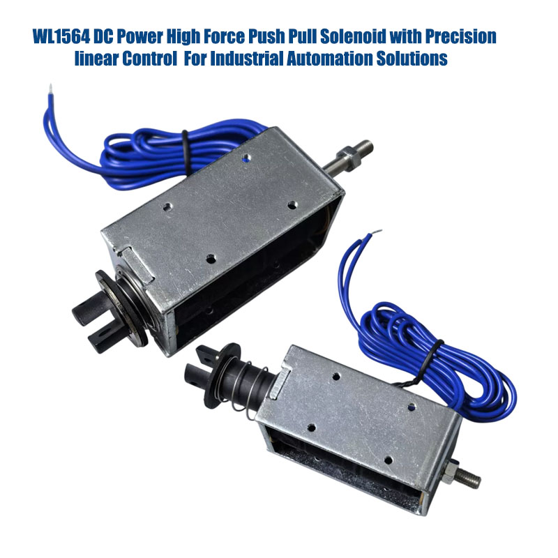
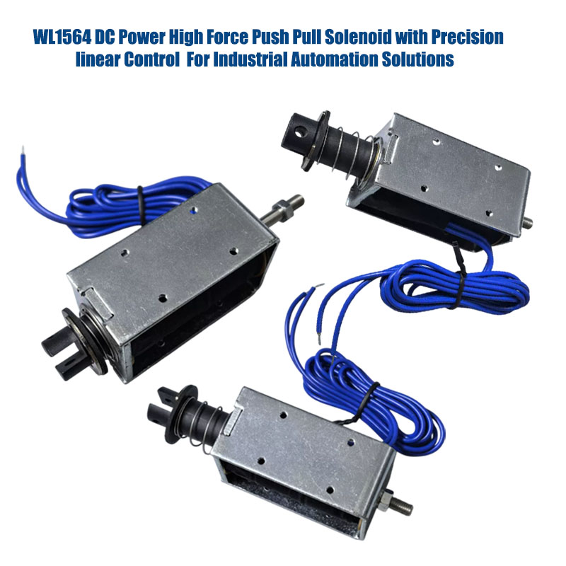
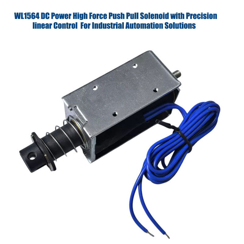
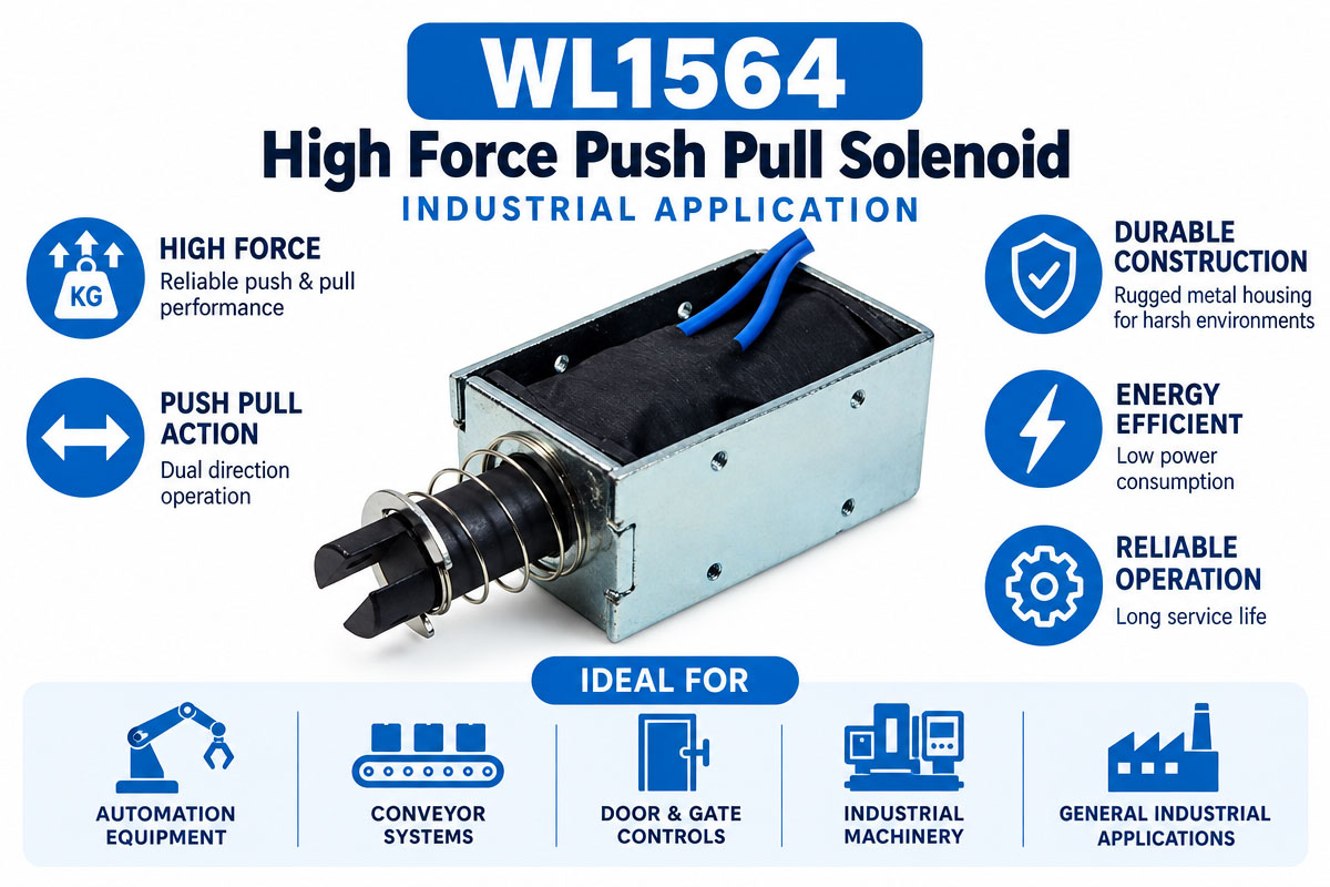
High Force Push Pull Solenoid for Industrial Equipment
Custom High Force Push Pull Solenoid for OEM Machines
High Force Push Pull Solenoid for Automated Machinery
High Force Push Pull Solenoid for Heavy Duty Applications
High Force Push Pull Solenoid for Linear Motion Control
High Force Push Pull Solenoid for Machine Control Systems
High Force Push Pull Solenoid for Industrial Equipment
Custom High Force Push Pull Solenoid for OEM Machines
High Force Push Pull Solenoid for Automated Machinery
High Force Push Pull Solenoid for Heavy Duty Applications
High Force Push Pull Solenoid for Linear Motion Control
High Force Push Pull Solenoid for Machine Control Systems

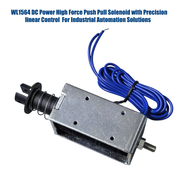
WL1564 High Force Push Pull Solenoid for Automation solutions

The high force push pull solenoid is an electromagnetic actuator combined with a mechanical design, which allows for the generation of significant linear force in a small-sized body. Such devices convert electrical energy to controlled mechanical movement and may be designed for push, pull, or push-pull operations.

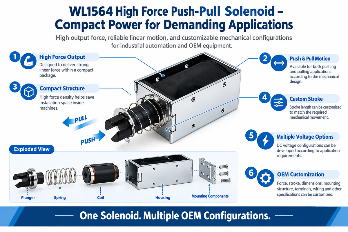
High force push pull solenoid usually require more efficient magnetic field, more solid construction, proper optimization of air gaps, optimal coil design and mechanical load capacity compared to regular solenoids. Engineers are able to customize voltage, force, stroke, duty cycle, mounting configuration, plunger dimensions, return mechanism, insulation and connectors according to the application.

The High force push pull solenoid is used in industrial automation equipment, machine tools, automatic locks, valves, dispensers, transportation equipment, material handling systems and OEM equipment. In order to select a solenoid, it is necessary to take into account the force needed at the particular stroke, frequency of operation, space available for the installation, thermal conditions, power supply and mechanical load. Well designed solenoid may provide reliable linear actuation for the industrial applications.

High Force Push Pull Solenoid Product Overview

The high force push pull solenoid is an electromagnetic linear actuator, used in applications where higher forces than those provided by compact solenoids are needed. We are able to customize product configurations to your force, stroke, voltage, current, duty cycle, dimensions, mounting method, shaft design, return mechanism, and environmental requirements. Depending on the application, manufacturers may optimize the magnetic circuit, coil winding, plunger geometry, spring characteristics, and housing design. Industrial OEM solenoids are also designed according to the customer’s open installation space and mechanical interface. Typical applications include automation equipment, locking systems, valves, machine mechanisms, material handling, and specialized industrial machinery requiring reliable electromagnetic linear motion.

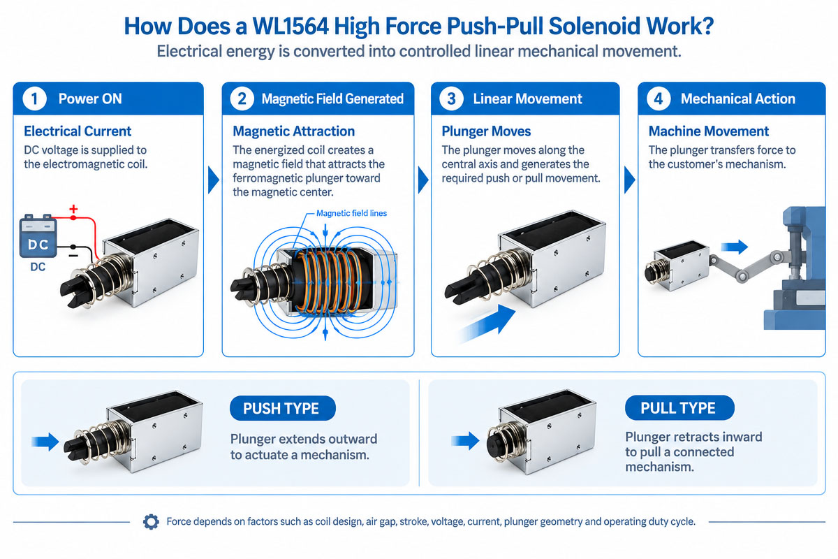
The Working Principle of a High Force Push Pull Solenoid

Such devices are based on the principle of electromagnetic force.

Step 1: Electrical Input

Voltage application results in the creation of electrical current in the copper winding of the solenoid.

Step 2 – Create a Magnetic Field

Powered by the electric current, the coil creates a magnetic field around the magnetic circuit inside the device.

Step 3 – Plunger Motion

The plunger is attracted to the point where the magnetic circuit is the most powerful due to the magnetic field.

Step 4 – Output (Mechanical)

At this stage the plunger performs mechanical motion. This motion may be the following depending on the design of the solenoid:

Displace the component.

Extract the component.

Activate the lock.

Open/close the valve.

Move the linkage.

Unfasten the clasp.

Control the operation of the machine mechanism.

Step 5 – Return Motion

The removal of power will result in the returning of the plunger to its initial position by such methods as

Spring returning mechanism

External mechanical pressure

Gravity

Other electromagnet coils

Latching mechanism

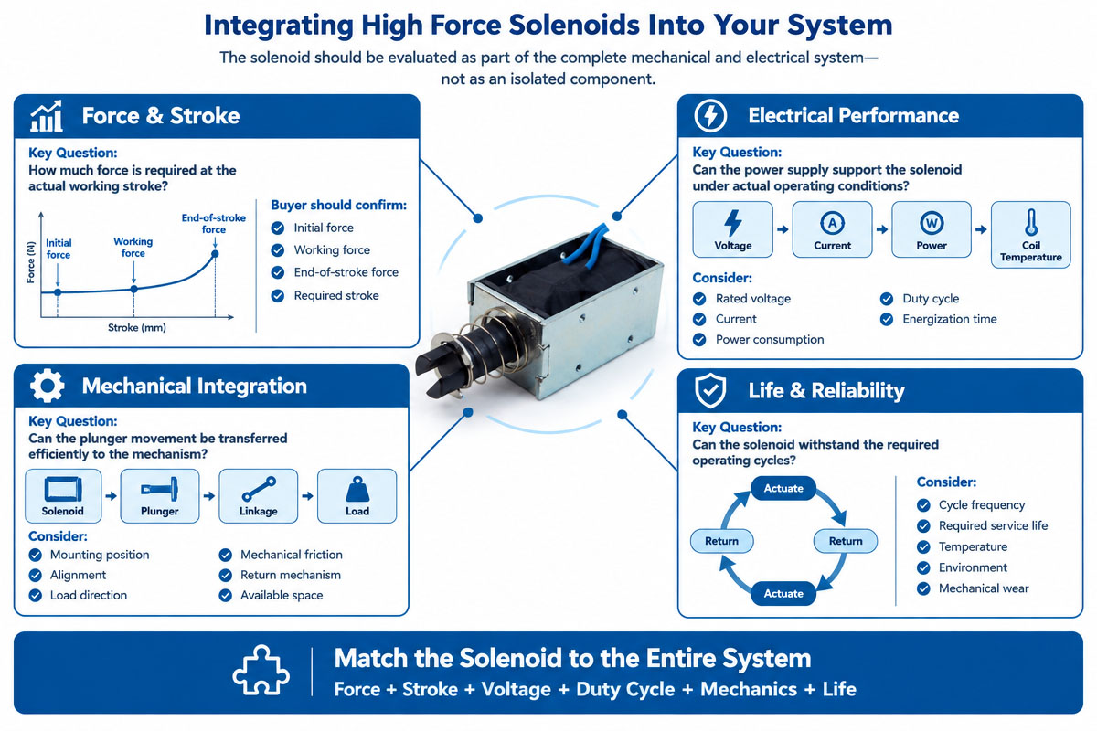
The available force changes greatly depending on stroke and air gap. The specification of the maximum force is not enough for selecting an industrial solenoid. The engineers at the place of operation will have to find out the force needed.

The Essential Characteristics of a High Force Push Pull Solenoid

The high-force push-pull solenoids are designed for the production of the highest electromagnetic output and reliable linear motion and mechanical integration according to the application. The typical characteristics include high starting force, an optimized magnetic circuit, a compact design, a customizable stroke, flexible mounting, strong metal parts, and voltage/duty cycle configurations. Depending on the application, the solenoid may be equipped with return springs, threaded shafts, mounting brackets, connectors, sensors, or protective coating. The specifications of the coil may be optimized for continuous, intermittent, or short-term operations. High industrial versions are made from durable materials and using a controlled manufacturing process. Customization of OEM enables the customization of force, stroke, dimensions, electrical characteristics, and mechanical interface according to the particular equipment.

Custom High Force Push Pull Solenoid Product Vidoe

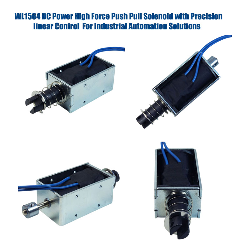
Custom High Force Push Pull Solenoid Detailed Display

High Force Push Pull Solenoid Technical Data Sheet

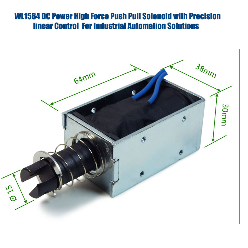
Brand Weilong Technology Model Number WL1564
Rated Voltage (V) DC12V or 60V Rated Power (W) 11 W–120 W
Work Mode Push and Pull Holding Force (N) 3–3500 Gf
Stroke (mm) 2-20 MM Customized Working Duty Continuous or intermittent
Service Life 200 Thousand Times Certification CE, RoHS, ISO9001,
Material Superior Magnet Iron Lead Wire Length (mm) 200 MM
Install Style Screw mounting hole Tolerance of Dimension ± 0.1 MM
Water-proof None Insulation Class B
Hi-Pot Test AC 600V 50/60Hz 2s Non-excitation Holding Force 0
Working Temperature -10°C-100°C Duty Cycle 1-100%
Thread Depth (mm) / Payment Term TT, or LC at Sight
Sample Order Yes. Warranty 1 Year
MOQ 1000 pcs Supply Ability 5000 pcs per week
Delivery Time 30 Days Port of Loading Shenzhen

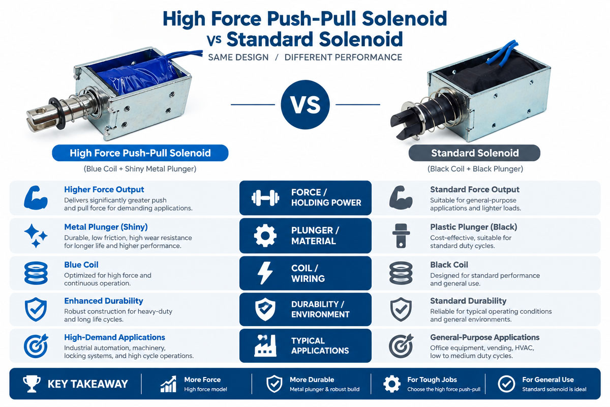
High Force Push Pull Solenoid vs. Standard Solenoid: Same Design, Different Guide

High Force Push Pull Solenoid VS Standard Solenoid

Designs of a standard solenoid and a high force push pull solenoid could be very similar. Both of them contain coil, magnetic core, plunger, housing, mechanical return system, etc. However, engineering approaches in these cases could be different. And it is necessary to say that higher force is not only more electrical power of the solenoid.

Magnetic Circuit

A standard solenoid can be designed for generic force and stroke requirements. The high-force push-pull solenoid design includes more details concerning the magnetic circuit, pole geometry, air gap, magnetic material, and flux path.

The goal is to provide useful magnetic force at the required position and to make the whole actuator compact.

Force vs. Stroke

It is one of the main differences between these designs.

A standard solenoid can be used when only moderate force is required and the stroke is relatively short. The push-pull solenoid with high force is used when the application demands more mechanical output.

Both of these designs use the same basic principle. Available electromagnetic force is dependent on the position of the plunger.Therefore, a comparison of two solenoids in terms of the maximum force will be wrong. One should compare force at the required stroke.

Coil Design

The high-force solenoid may require an optimized coil to create enough magnetic flux in the given volume.

But heat generation will increase as the coil power grows. Therefore, it is necessary to take into account coil resistance, current, wire size, insulation, energizing time, duty cycle, and thermal dissipation in unison.

The mechanical requirements are smaller, so a standard solenoid can use a coil with lower power.

Mechanical Design

Higher force applications put more requirements on the plunger, shaft, guide, spring, mounting points, and surrounding machine structure.

The guide system is especially important. If the plunger is not correctly aligned, mechanical friction will increase and electromagnetic force will decrease.

Due to this, high-force design should not depend only on the coil and magnetic circuit. The whole mechanical system should be designed for carrying the anticipated load.

Push and Pull Requirement

The standard solenoid is generally called the pull or push type actuator.

Push-pull configuration means that the attention is paid to the mechanical integration of the actuator with the machine. The same basic electromagnetic design could be used with different shaft, spring, linkage, or mounting configurations.

For OEM applications, one should know from the customer:

Pulling force

Force to push

Bidirectional mechanical operation

Spring return

External return

Single-cycle operation

Cycling over and over

Cycle of Duty

Standard as well as high-force solenoids should be chosen in accordance with the duty cycle.

For example, a solenoid that is energized for a fraction of a second several times in several minutes will have different thermal requirements from a continuously energized solenoid.

So, thermal design becomes especially important for high-force applications where more electrical input will be required to provide higher force.

Application Choice

When the requirements to force, stroke, duty cycle, and environment are not strict, one should use the standard solenoid.

A high-force push-pull solenoid should be used when higher actuation force or stronger mechanical output is required for the machine and within the given installation envelope.

Therefore, the choice of the solenoid should be made on the basis of the full working point, including force, stroke, voltage, current, duty cycle, frequency, temperature, dimensions, load, and service life requirements.

Buyer’s Perspective

For the OEM buyer, the most useful specification is not the following one:

“We need a high-force solenoid.

Much more useful specifications would be:

“X N force, X mm stroke, DC24V, X% duty cycle, X cycles, in these dimensions.

This specification will give the solenoid manufacturer enough information to define the magnetic, electrical, mechanical, and thermal requirements.

In summary

The basic electromagnetic principle remains the same, but the design guide is different when higher force, heavier load, more compact size, or a demanding industrial duty cycle is required. Therefore, the high-force push-pull solenoid is a system-level design and not a stronger version of the standard solenoid.


High Force Push Pull Solenoid Industrial Application

Custom High Force Push-Pull Solenoid Industrial Application

Controlled electromagnetic linear movement is required in many industrial devices, and the high force push pull solenoid is extensively used for this purpose. They are able to activate mechanical mechanisms, clamps, stops, gates, latches, and positioning devices in industrial automation. The small size of such devices makes them perfect for machines where the pneumatic or hydraulic cylinders are not enough. In machine tools the high force push pull solenoid is used to activate locking mechanisms, mechanical releases, indexing systems, and auxiliary machine operations. They are used to activate divers, sorters, stops, and material handling components on the automated production line.

They are used in industrial valve systems, especially in cases when the electromagnetic actuator has to displace a valve element against mechanical resistance. Other applications include automated doors, dispensers, packaging machines, vending machines, access control systems, transportation mechanisms, agricultural equipment, and specialized OEM equipment. In case of high load engineers have to evaluate the actual force needed at the working stroke instead of the nominal maximum force specification. The duty cycle and operating frequency should be taken into account since the repeated activation causes overheating of the coil. If it is well designed, the high force push pull solenoid is a simple electrically controlled alternative to mechanical or fluid-powered actuation systems.

Why are high force push pull solenoid preferred in industrial automation?

Modern machines require compact, electrically controllable and repeatable mechanical movement. High force push pull solenoid becomes more and more useful in the field of industrial automation.

Modern automation equipment becomes modular and limited in space. Moreover, one can obtain direct linear action without using air compressor, tubes, valves, and pneumatic infrastructure.

Another important aspect is electrical control. Solenoids can be controlled by relays, outputs of programmable logic controller (PLCs), MOSFET circuits, drivers, etc. This helps to integrate the actuator into the automated control sequence.

Customization of actuators is very important for OEM machines. One does not need to design the machine based on the standard actuator. It is possible to specify required force, stroke, voltage, dimensions of mounting, duty cycle, shaft configuration, and electrical interface.

For high-load applications, development engineers are not able to increase force anymore. One has to balance size, energy consumption, heat generation, response time, service life and installation constraints.

So, high force push pull solenoid is especially interesting for industrial automation systems where electromagnetic actuators can replace or supplement conventional mechanical, pneumatic, or hydraulic mechanisms.

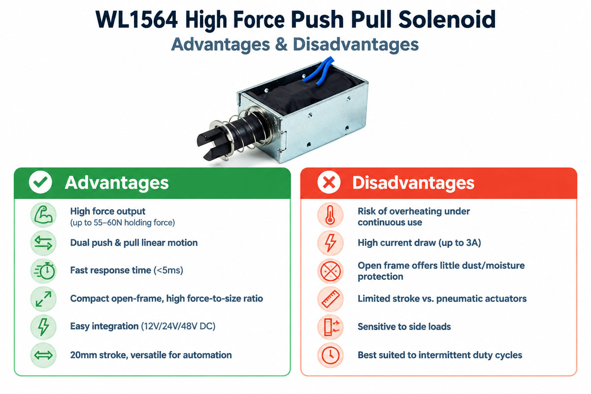
High Force Push Pull Solenoid Advantage and Disadvantage

High Force Push Pull Solenoid Advantage and Disadvantage

High Force Push Pull Solenoid Advantage

High force push pull solenoid  has a number of benefits in terms of industrial equipment. The first benefit of such actuators is linear electromagnetic actuation without use of compressed air, hydraulic fluid or complex transmission mechanisms. They can provide fast action, relatively easy control, small size and repeatability of action. Special designs can be made in order to optimize force, stroke, voltage, mounting and duty cycle. In some cases a solenoid can help in reducing the number of additional components comparing with other types of equipment.

High Force Push Pull Solenoid Disadvantage

However, there are some drawbacks.

One of the drawbacks is dependence of solenoid force on stroke and magnetic air gap. A solenoid designed to provide high starting force might deliver relatively small force on a larger stroke. Another problem could be coil heating, especially in case of continuous or frequent operation. Energy consumption will be high in case when the solenoid is supposed to produce high force during a long period.

Wear and tear of plunger, spring, guide or linkage is also possible. Higher electrical power cannot guarantee increasing of the force due to magnetic saturation.

High force push-pull solenoids operate efficiently when all electrical, magnetic, thermal and mechanical properties of these solenoids are designed in interaction with each other rather than only taking into account advertised force.

The High Force Push Pull Solenoid  Trouble Shooting Guide

In case of nonstandard performance of high force push-pull solenoid one should first pay attention to its electrical and mechanical parts.

The solenoid has not moved

It is necessary to check if the correct voltage reaches the coil of the solenoid. Check wiring, connectors, switches, relays, and controllers’ outputs. Coil resistance must be checked and compared with the required one.

The solenoid has moved but produces insufficient force

It is necessary to check real stroke. Insufficient force could be caused by:

Excessive air gap,

Wrong plunger position,

Mechanical friction,

Excessive external load. One should make sure that force requirements are provided at required stroke.

Overheating of solenoid

Check voltage, time of energizing, duty cycle, operating frequency and ambient temperature. Intermittent duty coils can be used continuously what results in overheating.

Slow movement of plunger

Possible causes include:

Low voltage,

Excessive mechanical friction,

Dirty contacts,

Incorrect spring tension,

Wrong load. Make sure that control system provides required current.

Plunger doesn’t comeback

It is necessary to check the return spring, external mechanism, mounting alignment, contamination of the plunger.

Too much noise and vibration

Check mechanical mounting, plunger alignment, impact on stroke end, loose components.

Test the solenoid in case of repeated failure on the machine not separately from the actuator. Root cause can be found by recording voltage, current, force, stroke, temperature and cycle frequency.

High Force Push Pull Solenoid FAQs

1. How much force can a high force push-pull solenoid generate?

The available force is defined by the solenoid size, coil power, magnetic circuit, plunger position and stroke. One should specify the force for the actual working stroke and not for the maximum force.

2. What information should I provide when ordering a high force push-pull solenoid?

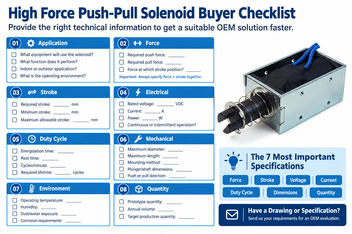
Application, required push/pull force, stroke, voltage, current or power, duty cycle, operating frequency, dimensions, mounting requirements, shaft configuration and quantity. OEM development is helped by drawings or samples.

3. Can a high force push-pull solenoid be used continuously?

The coil design and rated duty cycle are critical in this case. Some solenoids are intended for continuous duty, others are intended for intermittent or short-time service. Continuous operation requires good thermal design in order to avoid overheating.

4. How to select push or pull operation?

One should define how the solenoid interacts with the mechanism. In case when the actuator should pull a component back the pull configuration can be used. If the actuator pushes the component outwards then the push configuration should be used. In addition, return spring (or external mechanism) may be required.

5. Can I obtain a custom solenoid for my machine?

Yes. OEM applications can be customized with respect to force, stroke, voltage, coil, dimensions, mounting holes, shaft, spring, connector, housing and surface treatment depending on the machine requirements.

6. Why is the force less with longer stroke?

The distance between the plunger and the magnetic pole is very important for solenoid electromagnetic force. The available force normally decreases with growing air gap. So, the buyers should ask for the force vs stroke graph in case of comparing several models.

7. How to prevent the high force solenoid from overheating?

One should check the rated voltage, current, energized time, duty cycle, cycle frequency, ambient temperature and installation conditions. An intermittent-duty solenoid should not be used continuously unless it is allowed by the manufacturer.

8. Do I need a custom high force solenoid or standard one?

If the force, stroke, dimensions, voltage and duty cycle of the standard product meet the requirements of the application then it can be used. In case when installation space, force requirements, mechanical interfaces or operating conditions do not match the available standard products one should consider the OEM de

How to Choose a High Force Push Pull Solenoid

The mechanical requirements should be the starting point in the selection of a high force push pull solenoid and not the available product catalog.

1. Find the force you need

Find out the minimum force at the actual position. The force of the solenoid reduces when the plunger is displaced from the magnetic pole. Thus, the statement “100 N force” is not sufficient without the stroke.

2. Explain the stroke.

Specify the actual stroke, e.g., 3 mm, 5 mm, 10 mm, or 20 mm. Don’t choose a very long stroke solenoid just because the maximum stroke looks very attractive.

3. Adjust the working voltage.

The DC12V, DC24V, and other DC voltages are the common needs in industry. The coil needs to be optimized for the particular power supply and control electronics.

4. Duty cycle check

Does the solenoid work continuously, intermittently, or with short pulses? If a coil works continuously, it will overheat if it is designed for intermittent operation.

5. Consider the operating frequency.

A machine, which works multiple times per minute, requires a different solenoid than a machine, which works hundreds or thousands of times per hour. Frequency of cycles determines the heat accumulation, wear, spring fatigue, and service life.

6. Measure installation dimensions.

Check the full dimensions, mounting holes, shaft diameter, shaft length, connector location, and space for the movement.

7. Check load direction.

Determine if the application needs pulling, pushing, or both. The actual loading of the solenoid may vary greatly using the mechanical linkage.

8. Consider the environmental conditions.

The final design should be determined only after evaluation of the requirements for temperature, humidity, dust, oil, vibrations, water, and corrosion.

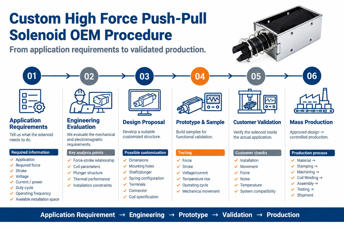
9. Prototype testing

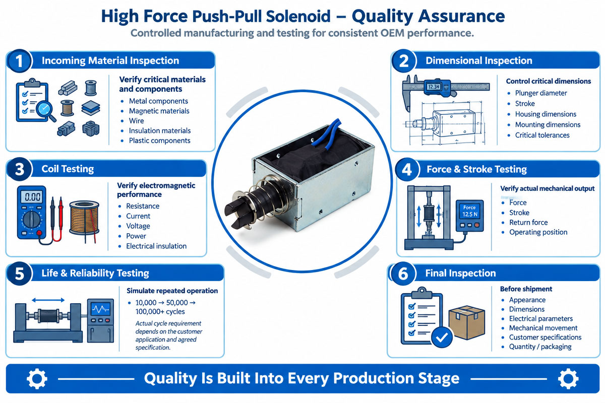
Test the solenoid before mass production under the real voltage, load, stroke, duty cycle, temperature, and mechanical installation conditions.

For OEM projects, such parameters are provided to the manufacturer for the selection/development of a high-force push-pull solenoid for the particular application.

Common Pitfalls to Avoid When Designing High Force Push Pull Solenoid

The performance problems are usually caused by the number of design mistakes.

Error 1: Push without a stroke

Always indicate the force needed at a certain stroke.

Error 2: Considering the maximum force as the operating force.

The maximum force is close to the start position. The working force can be much lower.

Mistake #3: Forgetting about the duty cycle.

The high-force coil produces a lot of heat. You need to find out the expected time of energization and cycle frequency.

Error 4: Choosing voltage first and then force.

“The voltage is important, but it’s the magnetic circuit, coil resistance, stroke, and available power all working together.”

Mistake 5: Not considering the return force requirements.

If a spring is used, its force should be considered in mechanical calculations.

Mistake 6. Not providing sufficient installation tolerance.

Shaft alignment, mounting tolerances, and surroundings should be considered.”

Mistake 7: Testing without the actual load.

The solenoid, which works when it is not loaded, may not work when installed in the machine.

Error 8: Forgetting about the temperature.

Coil resistance and performance depend on the temperature. Thermal testing is a part of prototype validation.

Mistake 9: Choosing the wrong size solenoid when you don’t have to.

An oversize actuator will add power, cost, size, and heat without improving the machine performance.


Get A Free Quote Now

Contact Form

Related Products

Related News

Scroll to Top

Get A Free Quote Now !

Contact Form
If you have any questions, please do not hesitate to contact us.
Weilong Solenoid Company Culture