

Chapter 1: Introduction of Solenoid Design
A solenoid is an electromechanical device that converts electrical energy into linear motion through electromagnetic force. The force generated in a solenoid is used to pull or push a plunger (armature), typically against a spring load or mechanical resistance. Electromagnetic force in a solenoid originates from the system’s inherent tendency to minimize magnetic reluctance in the magnetic circuit—pulling the armature into a position where there is less air gap.
Chapter 2: How a Solenoid Works?
From Current to Motion A solenoid works by converting electricity into a magnetic field, and then into mechanical force.
2.1. Electricity Generates Magnetic Force
When current flows through a coil, a magnetic field forms around it. In a solenoid, the wire is wound into several turns, enhancing the magnetic field strength. Strength of the magnetic field increases with: Number of turns (N) Current (I) This relationship is commonly known as the magneto-motive force (MMF), expressed in ampere-turns (NI).
2.2. Concentrated Magnetic Field
In Solenoid disng, the coil mnding is the key for making the stronge mangetic force. the coil is wound around a ferromagnetic core. The energized magnetic flux travels through the core and air gap to form a closed magnetic circuit. In this type of magnetic circuit, the air gap dominates magnetic reluctance and controls the majority of force output.
2.3. Linear Motion of the Plunger
A plunger in solenoid design is the important poit, normally made of iron or steel, is attracted to the point of maximum magnetic flux density. When the solenoid is energized: Plunger moves towards the pole piece Air gap is minimized Magnetic reluctance is further reduced Force is increased due to reduced air gap This generates pulling or pushing action, depending on the solenoid configuration.
Chapter 3: Key Solenoid Force Equation
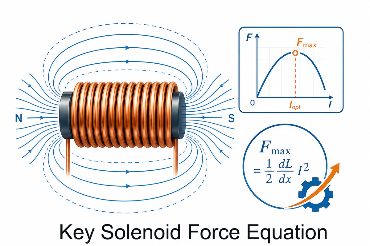
3.1 A commonly used simplified expression for the electromagnetic force in a solenoid (acting across an air gap) is:
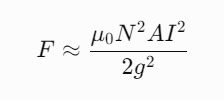
Where:
- FFF = electromagnetic force (N)
- μ0\mu_0μ0 = permeability of free space
- NNN = number of turns of the coil
- AAA = pole face area (m²)
- III = current (A)
- ggg = air gap length (m)
Key simplified takeaway:
The force can also be expressed conceptually as:
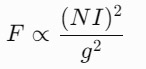
This highlights the most important solenoid design insight:
- Force increases with current squared
- Force increases with turns squared
- Force drops rapidly as the air gap increases
3.2 Solelnoid Design on Current Considerations
Increasing current increases magnetic force but increases heat loss (I²R losses). Resistance (R) Measured using a multimeter (AVO meter), it controls current flow at a particular voltage. Pole face area Larger pole face area leads to better flux distribution and increased force output. Air Gap Most important factor in solenoid performance. Even small increases in air gap can drastically reduce the force.
Chapter 4: Solenoid Design on Solenoid Coil Winding

4.1 Copper coils
Copper wire coils that generate magnetic field when energized. Yoke (Frame / Housing) Low carbon steel frame that forms and concentrates the magnetic circuit. Pole Piece Stationary magnet that focuses magnetic flux onto the armature. Plunger (Armature) Mobile magnet that reacts to the magnetic field. Guide Tube Non-magnetic housing (typically made of stainless steel) that ensures smooth linear motion. Air Gap Distance between the plunger and the pole piece. Determines force output. Push Pin / Output Rod Mechanism that transfers mechanical force to the load.
4.2 Solenoid desing on Coil Winding Techniques
Various winding methods significantly affect performance, efficiency, and thermal characteristics. 1. Circular (Single-Layer) Winding Cost-efficient and simple Good heat dissipation Moderate magnetic efficiency 2. Helical / Spiral Winding High turn density Compact structure Strong magnetic field generation Used in high force applications 3. Multi-Layer Winding Maximal number of turns in limited space High resistance and heat generation Used in compact or holding solenoids
The best force density: spiral winding
The best thermal stability: single-layer winding
The best space usage: multi-layer winding
Solenoid design Winding Techniques Factors Affecting Choice of Technique Required number of turns Operating current level Thermal considerations Duty cycle (continuous vs. intermittent) Space limitations Response speed requirements
Chapter 5: Solenoid Design Factors that affect the performance
Solenoid performance is a function of many variables, including electrical, magnetic, thermal, and mechanical. Understanding these variables is crucial in designing effective solenoid actuators for industrial automation, automotive, and IoT applications.
5.1 One of the important factors is coil and current.
The magnetic force generated by a solenoid is directly correlated with the current flowing through the coil. The higher the current, the stronger the magnetic field and magnetic force. However, too much current causes overheating and reduced efficiency. Closely related with current is resistance. Based on Ohm’s law (I = V/R), resistance controls the amount of current flowing at a given voltage. The higher the resistance, the lower the current and magnetic force. Coil resistance also increases as temperature goes up, which can have a limiting effect on performance during continuous operation.
5.2 solenoid force calculation
Another important variable in solenoid force calculation is the number of coil turns (N). Increasing number of turns increases the magneto-motive force (ampere-turns) and the magnetic field intensity. But this also increases coil resistance and inductance, slowing down the response.
5.3 Air Gap
Air gap length is another crucial factor. Since solenoid force is inversely proportional to the square of the air gap, even small increases in the gap distance decrease force output. Thus, it is important to have good mechanical design and tight tolerances.
5.4 Solenoid Desing on Material
Material choice is also very important. High permeability materials such as soft iron in yoke and plunger enhance magnetic flux and reduce energy loss. Poorly chosen materials lead to saturation and lower force output.
5.5 Temperature and duty cycle
Temperature and duty cycle also play a role. The higher the temperature, the higher is the resistance and lower is the current and force output. Continuous operation without appropriate thermal management will lead to reduced performance.
Chapter 6: Solenoid Design on Optimization of the Maximum Force
Maximization of solenoid force requires optimal electromechanical design. Since solenoid is an electromagnetic actuator, any improvement of design parameters leads to increased output force.
6.1. Minimize Air Gap Length (Most Critical Factor)
The air gap is the dominating factor influencing solenoid force. Force is inversely proportional to the square of the air gap length. Any reduction in air gap leads to a significant increase in force. Precise machining, tight tolerances, and optimal mechanical alignment ensure the shortest air gap during the operation of the solenoid.
6.2. Increase Ampere-Turns (NI Value)
The force of the solenoid is highly dependent on the magneto-motive force, which is a product of number of coil turns (N) and current (I). Increasing either parameter leads to increased magnetic field intensity. But: • More turns increase resistance and inductance • Higher current increases heat generation Optimized coil design increases NI value while controlling thermal effects.
6.3. Use of High-Permeability Magnetic
Materials Proper choice of materials for the core, yoke, and plunger is important. Soft iron or low carbon steel with high permeability allow more efficient magnetic flux conduction and prevent saturation. This allows for efficient transformation of electrical energy into mechanical energy.
6.4. Optimize Pole Face Area and Geometry
An increased cross-sectional area of the pole face increases flux distribution and force output. Also, proper shaping of the pole piece reduces the magnetic leakage and concentrates magnetic field across the air gap.
6.5. Increase Coil Fill Factor and Optimize Winding Design
Higher fill factor means more copper wire packed in limited space, leading to higher NI without an increase in the size. Optimized winding technique such as helical and tightly packed multi-layer can significantly increase performance.
6.6. Manage Thermal Effects
Increased temperature rises resistance of the coil, which decreases current and magnetic force. Techniques of thermal management:
- Use heat resistant insulating materials
- Ventilation or heat sink •
6.7 Duty cycle optimization for intermittent operation _
Reduce Magnetic Leakage and Losses Effective design of magnetic circuit leads to minimum flux leakage. It can be achieved by:
- Minimizing air gaps outside the stroke length
- Closed magnetic loop structure
- Preventing magnetic path discontinuities
Chapter 7 : Electromagnetic Force for Industrial Applications
magnetic force is probably the most widely used physical phenomenon in the modern industry. It is a basis for motion control, energy transformation, and automation. Converting electrical energy into the mechanical force, electromagnetic systems provide precise, fast and reliable operation in various industrial settings.
7.1 What Is Electromagnetic Force in Industry?
Electromagnetic force is generated in industrial systems through the interaction of an electric current with a magnetic field. In industrial systems, this force is used to produce motion, typically linear or rotary, depending on the design of the device. It plays a key role in: • Actuators and solenoids • Electric motors • Relays and contactors • Valves and fluid control systems • Industrial automation equipment
7.2 Main Industrial Applications of Electromagnetic Force
7.2.1. Solenoid Actuators Solenoids are one of the most direct industrial applications of electromagnetic force. They convert electrical energy into linear motion by pulling a movable plunger.
7.2.2 Common uses:
- Hydraulic and pneumatic valves
- Fuel injection systems
- Locking and latching mechanisms
- Medical dosing devices Fast respconsidered. act design make solenconsidered. n automation systems.
7.3 Importance of Electromagnetic Force in Industrial Applications
Electromagnetic systems are preferred because of the following features:
- Fast response time
- High precision control
- Compact and scalable design
- Low maintenance requirements
- High reliability in automation environment These features make electromagnetic force an integral part of Industry 4.0 and smart manufacturing systems.
7.4 Key Factors in Industrial System Design To achieve maximum performance, it is important to optimize:
- Coil current and voltage
- Magnetic circuit efficiency
- Air gap minimization
- Thermal performance
- Material selection (high permeability cores)
- Duty cycle and operating conditions
Chapter 8 : Electricity Transmission and Distribution on Solenoid Design
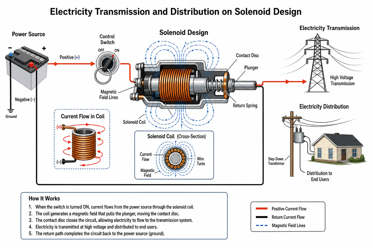
Solenoids are not responsible for high voltage power transmission, but they play an important auxiliary role in electricity transmission and distribution systems. They are widely used in control, protection, switching and automation equipment ensuring safe and efficient transmission of electricity over the grid. Modern power grids use solenoid based devices to enable fast mechanical switching triggered by electrical signals.
8.1 Role of Solenoids in Transmission
Power Systems Electricity transmission systems operate at high voltage to reduce losses during long distance transmission. In this system, solenoids are used in control devices such as:
- Circuit breakers
- Protective relays
- Load switching mechanisms
- Tap changers in transformers
- Remote switching systems These devices use the electromagnetic force to rapidly open or close electrical contacts under normal and faulty conditions.
8.2 Solenoid-Based Actuators in Circuit Breakers
One of the important applications of solenoids in transmission power systems is actuation of circuit breakers. When a fault occurs:
- Control signal energizes the solenoid coil
- Electromagnetic force rapidly pulls the plunger
- Mechanical linkage actuates circuit breaker contacts
- The circuit is disconnected in milliseconds This fast reaction helps prevent equipment damage, fire hazard and grid instability.
8.3 On-Load Tap Changing Application of Solenoids In distribution networks
Solenoids are used in on-load tap changing (OLTC) in order to adjust the voltage levels. OLTC:
- Solenoids actuate switching contacts in the transformer •
Voltage is adjusted without interruption of power supply
- Ensures stable voltage for consumers This is required to maintain stable voltage level in urban and industrial areas.
8.4 Solenoids in Distribution Automation Systems
Modern smart grids use automated distribution systems where solenoids are used for remote operation.
Application areas:
- Remote controlled switchgear
- Automatic reclosers
- Sectionalizers for fault isolation
- Switching nodes of smart grids These systems increase reliability and reduce downtime during faults.
Chapter 9: Solenoid Design in Power Systems
For reliable operation in power transmission and distribution systems, solenoid design should has:
- High Force and Quick Response Faulty conditions require rapid switching. Solenoid design should generate sufficient force to open or close contacts in milliseconds overcoming spring force and mechanical resistance.
- High Temperature Stability Continuous operation in substation requires: • Heat resistant coil insulation • Stable resistance over temperature • Effective heat dissipation
- Electrical Isolation Solenoids should be designed for high electrical stress and no insulation breakdown.
- Mechanical Durable Solenoids should be designed to withstand thousands of operations without failure.
- Optimized Magnetic Circuit To achieve maximum performance:
- Minimize air gap
- Use high permeability steel core
- Reduce magnetic leakage paths
- Optimize ampere-turns (NI)
Chapter 10: How to Avoid Common Mistakes before making the solenoid design

Solenoid design seems easy enough, but in practical applications many failures are caused by repeated solenoid design mistakes. Poor force output, overheating, slow response, or premature failure are not random events but predictable design errors. They can be easily avoided with proper planning as below:
10.1 Ignore the Air Gap (Most Critical Mistake) during solenoid design
One of the common solenoid design mistakes is the underestimation of the importance of air gap. Since electromagnetic force rapidly drops when the gap is increasing:
- Small increase in gap can significantly reduce force output
- Uneven mechanical alignment leads to unpredictable behavior
- Wear leads to increased gap and inefficiency
How to avoid it:
- Design tight mechanical tolerances
- Use rigid guide structure
- Minimize moving distance when possible
- Ensure proper alignment of the plunger and pole face
10.2. Solenoid deisng on Oversize Current
Without Thermal Control Increased current is a common way to increase force, but it often leads to overheating. Problems:
- Degradation of coil insulation
- Increased resistance due to heat
- Decreased reliability
- Possible coil burn-out
How to avoid it:
- Design for continuous duty cycle, not for peak force
- Use proper wire gauge and insulation class
- Perform thermal simulation in design phase
- Increase heat dissipation in housing design
10.3 . Inefficient Coil Design and Low Fill Factor
Inefficient coil design leads to low magnetic force. Common mistakes:
- Too few turns (low ampere-turns)
- Excessive air gaps between turns
- Inefficient winding distribution
How to avoid it:
- Optimize ampere-turns (N x I balance)
- Use precise winding technique
- Increase copper fill factor without overheating
- Use proper winding method (single-layer vs multi-layer) __
10.4. Poor Magnetic Materials Choice Material choice affects magnetic efficiency.
Problems:
- Magnetic saturation
- Magnetic leakage
- Low force output How to avoid it:
- Use high permeability soft iron or low carbon steel
- Use proper heat treatment of core materials •
10.5 Avoid inconsistent magnetic properties of the materials
Ignore Response Requirements Some solenoids fail not because of the force output, but because of the dynamic response. Problems:
- Excessive plunger mass
- High friction in guide tube
- Poor return spring design
How to avoid it:
- Reduce moving mass where possible
- Use low friction guide surfaces
- Balance the spring force with magnetic force
- Optimize stroke length for speed of the application
10.6. Ignore Duty Cycle Restrictions
A solenoid design for intermittent use will fail in continuous operation.
Common mistakes:
- No thermal margin in design
- No cooling design
- Continuous energizing of the solenoid beyond ratings
How to avoid it:
- Determine duty cycle in early design (continuous vs intermittent)
- Apply derating for temperature conditions
- Use thermal protection if required
10.7. Poor Mechanical Integration
Even the most optimized electromechanical system fails in poor mechanical integration.
Problems: •
Misalignment of plunger and load
- Excessive side loads or friction •
Mechanical binding during motion
How to avoid it:
- Ensure precise alignment during assembly
- Use guide tubes and bushings
- Test under real mechanical load conditions
Chapter 11: About FAQs of Solenoid Design
11.1 What is a solenoid in simple terms?
A solenoid is an electromechanical device that converts electrical energy into linear motion. The current flowing through the coil generates the magnetic field, which attracts the metal plunger and produces the movement used in valves, locks, and automation systems. _
11.2 How does a solenoid generate force?
A solenoid generates force due to electromagnetic attraction. Current in the coil generates the magnetic field that pulls the plunger towards the center of the coil in order to minimize the air gap and magnetic reluctance. The force is increased when the air gap is decreased.
11.3 What is the most important factor in solenoid design?
Air gap is the most critical factor. The force of a solenoid is inversely proportional to the square of the air gap, thus, even small increase in distance significantly affects performance.
11.4 How do I increase solenoid force when I making a solenoid deisng? The force can be increased by:
- Increasing number of turns (N)
- Increasing current (I)
- Reducing air gap
- Using high permeability magnetic materials
- Increasing pole face area But, thermal limits should be considered. 11.5Why doesconsidered. overheat?
11.5Why does my solenoid overheat?
Overheating is usually caused by excessive current, high duty cycle, or poor heat dissipationconsidered. ature rises, resistance of the coil increases, decreasing efficiency and reliability.
11.6 What materials are best for solenoid cores and plungers?
High permeability soft iron or low carbon steel are used most often, since they allow for efficient magnetic flux conduction and energy loss prevention. They also prevent magnetic saturation under load.
11.7 What affects solenoid response speed?
Speed of response is determined by:
- Plunger mass (the lighter is the plunger, the considered. es)
- Coil inductance
- Voltage level
- Spring force balance
- Friction in the guide system The optimization of mechanical and electrical design improves switching speed.
11.8 Can Solneoid operate contiinousousley?
Yes, but only if they are designed for continuous duty. Many solenoids are designed for intermittent use. Continuous operation requires thermal design, heat resistant insulation, and current control to prevent overheating.
Chapter 12: Solenoid Design Conclusion
Solenoid is an electromechanical actuator, converting electrical energy into linear motion. The performance of the solenoid depends on the balance between electrical input, magnetic circuit, material selection, and geometry. The understanding of electromagnetic force generation and behavior across the air gap is crucial for designing efficient and reliable solenoid systems used in industrial automation, automotive systems, and smart devices.


