Chapter 1: Introduction of Air Core Inductor Calculation
Precise air core inductor calculation is crucial in designing radio-frequency circuits, NFC antennas, wireless communication systems, power electronics systems, and highly precise sensors. Air core inductors differ from ferrite core inductors due to their high linearity, no magnetic saturation, and low high-frequency losses.
Calculating air core inductors does not involve a magnetic core amplification mechanism. All of its inductance depends solely on the geometry of its coil construction. Inductance calculation needs to be done quite early, tested by making and measuring a prototype and correcting empirical values.
The Wheeler formula for air-core coil design was created based on numerous experimental measurements. To this day, it remains the de facto standard for calculating both single-layer and multiple-layer air core inductors.
In this article, you’ll learn about:
- Air core inductor calculation and Wheeler Formulas for Single and Multiple Layers
- Methods for engineering correction of inductance calculations ·
- Practical examples of designing Air Core Inductor Calculation
- Typical mistakes in the process of Air Core Inductor Calculation
- Frequently asked question about Air Core Inductor Calculation
Chapter 2: Air Core Inductor Calculation and Its Fundamental Concepts
Inductance is defined as a ratio of magnetic flux linkage over a current through the circuit.
L = Ψ/I L = I/Ψ where: • L – Inductance (H)
- Ψ = Magnetic flux linkage
I—Current (A) Inductance is used in all practical applications as follows:
•μH (micro-henries) ·nH (nanohenries)
As an air core inductor calculation doesn’t contain any magnetic material, its relative permeability approaches the following:
\mu_r \approx 1 μr≈1
This design provides excellent linearity for the air core inductor, avoiding issues such as core saturation, hysteresis loss, and permeability drift.
However, some of the magnetic fluxes leak out both ends of the coil. Theoretical inductance calculations become very complex when accounting for flux leakage. That’s why Harold Wheeler suggested using empirical formulas to solve this problem. These formulas are the cornerstone of modern air core inductor calculation methods.
Chapter 3: Air Core Inductor Calculation for Single Layer Coil (Standard Wheeler Formula)
For most cylindrical single-layer coils:
L(μH) = D²N²/(45.72D+101.6l) where:
L(μH) = Inductance (in microhenries)
D – average coil diameter, mm
N – number of turns
l – length of winding, mm
Application range
The above formula provides high accuracy when:
- l/D > 0, 4;
- the coil is cylindrical;
- tight windings.
The typical calculation error of the Wheeler formula is less than 1%.
Chapter 4: Short Coil & Flat Air Coils Correction for NFC Applications
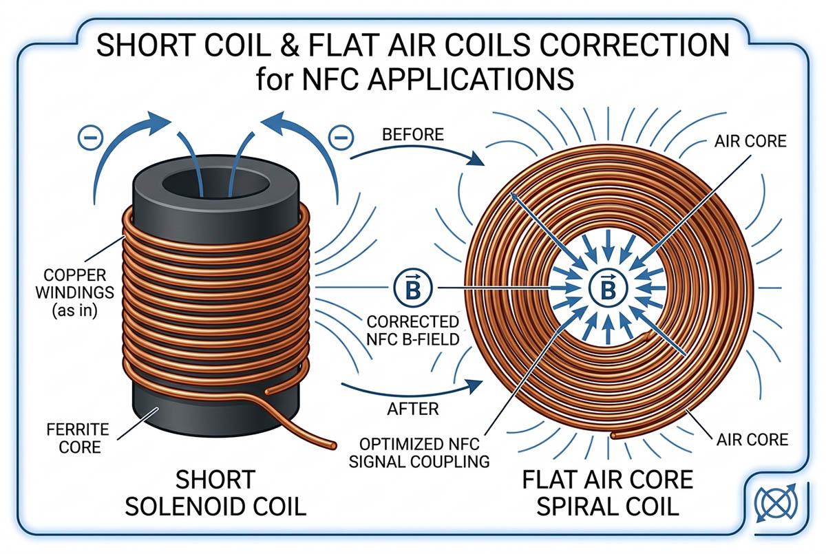
Most NFC and RFID antennas feature a very short winding length compared to the coil diameter.
When: Where:
l/D < 0.4: The Wheeler formula tends to overestimate inductance.
Correction formula:
L = (D²N²/(45.72D+101.6l)) × Ks, where:
D = average coil diameter l = length of coil
Short-Coil Correction Factor for k s
l/D 0.1 0.2 0.3 0.4 ks 0.72 0.85 0.92 0.99
Very useful for antenna design:
- NFC antennas
- RFID reader coils
- coils for wireless charging
- sensor coils
Chapter 5: Air Core Inductor Calculation for Multi-Layer Air Core Coil
A much more accurate multi-layer air core inductor formula.
L(μH) = 0.394×(Davg²×N²)/(Davg+2.79l+3.55t), where: D avg = average coil diameter N = number of turns
l = length of coil
t = radial thickness of winding
Davg location:
Davg = (Dinner + Daughter)/2
Suitable for:
- RF choke
- Inductor for high current
- Rogowski coils
- power converter reactors
- industrial sensing coils
Chapter 6: Engineering Considerations in Air Core Inductor Calculation
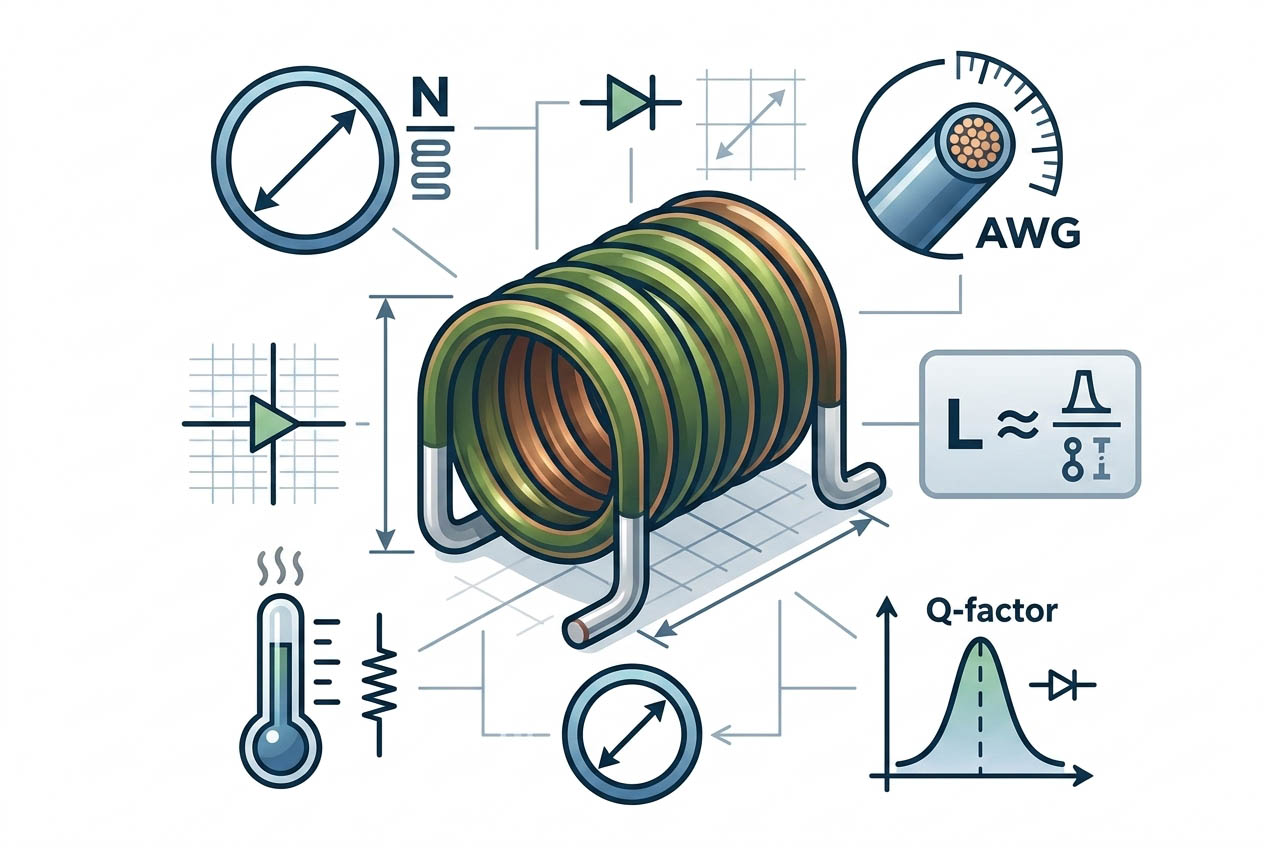
Even if Wheeler formulas are applied correctly, there are numerous practical aspects that influence the final inductance value.
6.1 Coil wire diameter and pitch of turns
All of the formulas are designed assuming tightly wound turns.
In practical applications: · enamel wire insulation increases turn spacing
- manual coil winding makes voids appear
- The coil becomes longer than calculated.
Typical inductance reduction: 3%-8%.
Recommendation: reserve additional turns.
- 2-5 % for RF coils
- 5-8 % for NFC coils
6.2 Insulation Between Turns
When designing multilayer coils:
- Wire diameter must be taken into account
- Insulation paper must be included
- Other spacers must be accounted for. Ignoring insulation diameter often leads to 3%-10% error.
6.3 Plastic Forming
Materials like PVC, PA, or ABS don’t affect permeability like air does, but they take up part of the space in the magnetic flux.
The typical correction factor is 0.95-0.98. Recommended wall thickness: ≤10% coil diameter
6.4 High-Frequency Skin Effect
Above 10 MHz:
- current flows along the surface of conductor
- decreases the cross-sectional area of conductor
- measured inductance changes slightly
Standard correction: -3% to -1%
For higher frequencies above 50 MHz, electromagnetic simulation is recommended.
Chapter 7: How to avoid Common mistakes in Air Core Inductor calculation design
Four Inherent Error Sources
| Error Source | Cause | Typical Impact Magnitude |
| Flux Leakage | Magnetic flux diverges at both ends | Most pronounced for flat coils: 10%~20% |
| Insulation & Turn Gaps | Insulation coating, manual winding gaps | 3%~8% |
| Former Material Effect | Former occupies space, compressing magnetic circuit | 2%~5% |
| Skin Effect (High Frequency) | Effective cross-sectional area reduces >1MHz | 1%~3% (>10MHz) |
Mistake #1: using the incorrect formula for air core inductor calculation
Applying a standard Wheeler formula to flat NFC coils.
Overestimation of inductance up to 20-30%.
Solution: applying correction factor kₛ
Mistake #2: overlooking of turn spacing
Inductance of prototype is lower than expected. Solution: accounting for insulation thickness
Mistake #3: ignoring inter-layer thickness of Air Core Inductor Calculation
Multilayer coil calculations seem ok, but inductance is too low. Solution: adding insulation thickness to all layers
Mistake #4: wrong measurement setup
For proper measurements: · close to operating frequency
- away from any metallic objects
- without touching coil hands
- calibrated LCR meters
Examples of Air Core Inductor Calculation
Example 1: design of RF coil
Design specification
Diameter: 10mm,
length: 8mm
With the Wheeler formula:
Desired inductance: 120 nH
Results:
- turns needed: ≈ 9.8
- final design: 10 turns
Actual value:
- 123 nH (error: 2.5%)
Example 2: design of NFC antenna coil
Diameter: 40 mm, Length: 4 mm. Target inductance 2.2 μH
Since l/D = 0.1, we must apply the following: Ks=0.72 Calculated turns:
2 Production adjustment:
3. Resultant inductance:
2.18 μH within NFC tolerance range.
Example 3: multi-layer power coil calculation parameters
Davg = 30 mm, l = 15 mm
t = 6 mm
N = 120 turns
Resultant inductance:
- calculated: 18.7 μH
- measured: 18.1 µH
Deviation: 1.3% Ideal for use in production.
Chapter 8: Air Core Calculation Formula Quick Guide
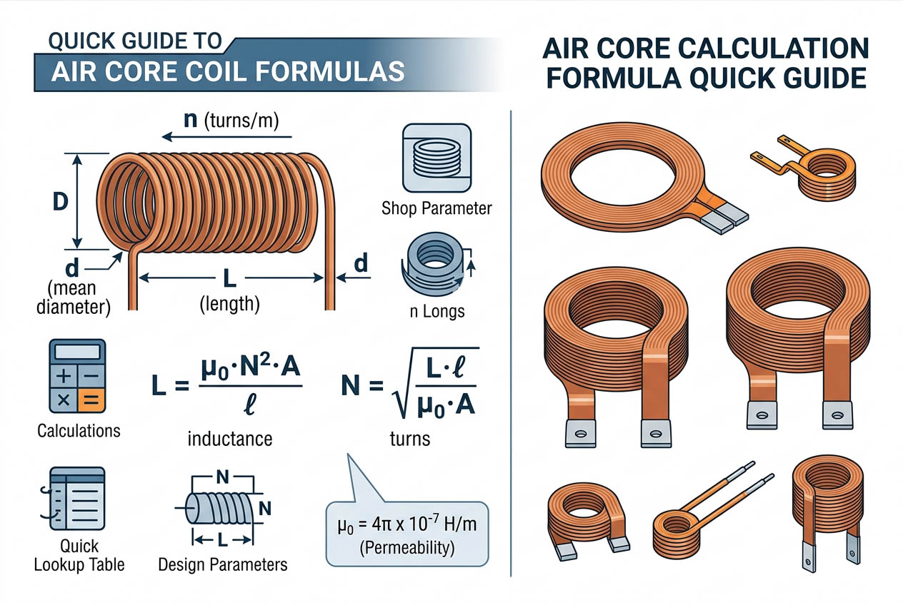
Air Core Inductor Formula Quick Reference Guide
Single-Layer Coil with Axial Wind
If l, the winding length, is greater than 0.4D (D is the average coil diameter in millimeters):
L(µH) = (D² x N²) / (45.72 x D + 101.6 x l)
where D – average coil diameter (mm)
N – total number of turns
l – winding length (mm)
Calculation error: less than 1%, if l > 0.4D
Short Coil Correction
In case of flat coils, such as NFC antennas, an additional coefficient Ks should be applied to compensate for the formula error:
L = (D² x N²) / (45.72 x D + 101.6 x l) x Ks
l/D: 0.1 0.2 0.3 0.4
Ks: 0.72 0.85 0.92 0.99
Important note: in case of flat coils, the l/D ratio should be considered before applying the calculation. Omitting the coefficient results in an error exceeding 20%.
Multi-layer Coil with Axial Wind
An additional parameter in the case of multi-layer winding (high-power choke, power inductor, etc.) is the radial thickness t:
L(µH) = (0.394 x D_avg² x N²) / (D_avg + 2.79 x l + 3.55 x t)
where D_avg is the average coil diameter (mm)
t – radial winding thickness (mm)
l – winding length (mm)
To be used: only if t + 0.5l < D_avg
Common pitfall: the radial thickness should include additional insulation between layers.
Chapter 9: Engineering Tips to Improve the Air Core Inductor Calculation
9.1 Core Engineering Application Scenarios (Quick Matching)
| Application Scenario | Applicable Formula | Typical Products | Key Considerations |
| NFC/RFID Wireless RF | Single-layer + Kₛ | Phone NFC antennas, reader coils | l/D < 0.4, must use Kₛ |
| RF High-frequency Circuits | Standard single-layer | Walkie-talkie LC oscillators, filter inductors | l > 0.4D, error <3% |
| High-power Power/Utility | Multi-layer | SMPS chokes, PV reactors | Include interlayer insulation |
| Industrial Sensing/Control | Adaptive | Rogowski coils, eddy current probes | Emphasize consistency & linearity |
| Medical/Aerospace/Military | Corrected single/multi-layer | Therapy coils, radar tuning inductors | Magnetic cores prohibited, high reliability |
| Instrumentation/Metrology | Standard formula | Calibration standard coils, lab solenoids | Combine with measured calibration |
9.2 Include Turn Gaps
Formulas do not take into account actual winding gaps. Due to wire insulation and manually wrapped turns, the measured value of inductance is always 3%-8% below the calculated.
Tip: Include a 2-5% margin on top of the number of turns during design. For flat NFC coil designs, add 5-8%.
9.3 Apply First-article Correction
Measure inductance of the prototype and calculate the following:
K = L_measured / L_calculated
Then use that correction for all subsequent coils of the same design.
9.4 High-Frequency Compensation (>10 MHz)
Due to skin effect, at high frequency (over 10 MHz), an inductor’s inductance decreases due to the reduction of the current flow cross-section.
Adjustment: reduce the calculated inductance by 1-3%.
9.5 Never Apply the Ideal Solenoid Formula!
This theoretical formula, L = (µ₀ x π x D² x N²) / (4 x l), does not consider flux leakage and cannot be used in real engineering calculations—errors can reach up to 20%.
Wheeler Formulas Comparison Table
9.6 Air Core Inductor Calculation Quick Selection Guide
| Coil Type | Formula | Typical Use Case |
| Slender single layer (l > 0.4D) | Standard single layer | RF oscillators, high-frequency filters |
| Flat single layer (l < 0.4D) | Single layer + Kₛ | NFC antennas, wireless charging |
| Multi layer | Multi layer Wheeler | Power chokes, utility reactors |
| Irregular or magnetic core | Not applicable | Use measurement or simulation |
9.6 Checklist Prior to Prototyping
✅ Accurate measurements: D, l and t
✅ Calculations according to l/D ratio
✅ Additional turns margin 2%-8%
✅ For multi-layer coil, account for insulation thickness in
✅ Plan to measure first article and find K
Using Wheeler formulas correctly saves you from blind prototyping, reduces time-to-market, and increases production consistency.
Chapter 10: Common FAQs about Air Core Inductor Calculation
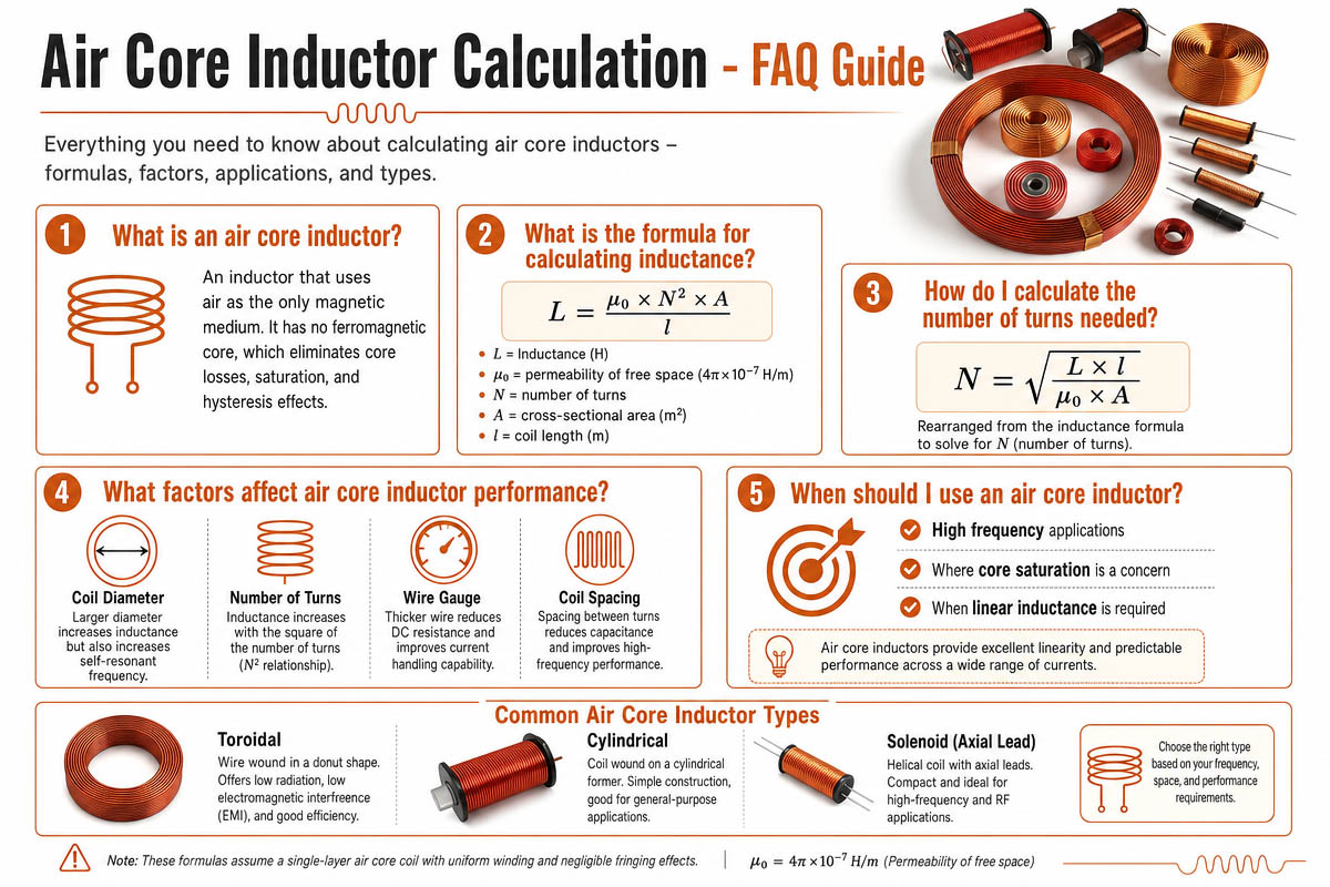
10.1 Why is my measured inductance always lower than the calculated one using the Wheeler formula?
Answer: This scenario is extremely common and the result of many mistakes made in coil calculations. The Wheeler formula assumes perfect winding without gaps between turns. Practically, due to the wire insulation thickness and human/machine winding, the gap exists inevitably. By this gap the effective length of the winding increases and, hence, inductance decreases by 3%-8%. Solution: Add 2%-5% additional turns when designing, and after measuring the first article, build a correction factor K = L_measured ÷ L_calculated for all other coils.
10.2 Can I use a regular Air Core Inductor Calculation Wheeler formula for the NFC antenna coil operating at 13.56 MHz? —NFC hardware engineer
Answer: No. Most likely not. And this is the top mistake in NFC design. NFC antenna coils have small diameters and are typically flat coils with an l/D ratio between 0.1 and 0.3. If the coil is short (l/D < 0.4), you need to use the short coil correction factor Ks. E.g., for l/D=0.1, it is Ks=0.72, meaning that a standard formula would overestimate the inductance by about 40%. (!) Calculate l/D and select the appropriate formula.
10.3 What is the difference between D and Davg? Sometimes, I see a term in air core inductor calculation.
Answer: Good question, because mixing them up would completely screw up the result. D (single-layer coil) is the average diameter of the winding, measured from the copper conductor center. For multi-layer coils, Davg = (inner diameter + outer diameter)/2. Using the latter parameter in a single-layer formula would provide incorrect results due to the radial build-up effect.
10.4 How should I take into account additional insulation paper layers in multi-layer coils?
Answer: In the multi-layer Wheeler formula, t (radial thickness) is taken into account. Engineers often estimate the radial thickness from the outer diameter of the copper wire and underestimate it, which leads to incorrect results and overestimated inductance. Properly: t_actual=(number of layers×wire diameter)+((number of layers-1)×insulation thickness). Just these extra 0.1 to 0.5 mm will make a difference in the inductance.
10.5 Does the former (bobbin) material affect the inductance?
Answer: Yes, as even in the case of PVC, PA, or ABS plastic, μᵣ is considered 1; still, this material displaces the air. Due to the high permeability of air, the magnetic field prefers it. The thick-walled bobbin squeezes the magnetic circuit, reducing the inductance by 2% to 5%. Correction factor: 0.95-0.98 Workaround: keep the bobbin wall thickness below 10% of the coil diameter. Measure a sample and apply this correction factor backward.
10.6 My RF coil with 100 MHz does not fit the calculation at all. Why is that?
Answer: Skin effect, parasitic capacitance, and high-frequency current distribution affect coils at frequencies > 10 MHz. The Wheeler formula is valid for the low-frequency current distribution. For RF applications, start from the downwards 1-3 percent adjustment. Electromagnetic simulation (e.g., HFSS, Sonnet) is recommended for designs >50 MHz. Don’t forget the importance of the LCR meter frequency in measurements.
10.7 Are there any ways to skip calculation every time for manufacturing batches?
Answer: Definitely yes, try the first article correction method.
-First of all, calculate the theoretical inductance according to the relevant Wheeler formula.
-Wind a sample and measure its actual inductance.
-Calculate the correction factor K = L_measured ÷ L_calculated
-To achieve the required inductance for the remaining coils, multiply the desired number of turns by 1/K or use L_calculated×K as the final design inductance target.
One sample saves tons of recalculations and rewinds.
10.8 Can the Wheeler formula be applied for square and rectangular air coils?
Answer: No, as it has been experimentally determined for cylindrical (round) coils only. Alternative methods should be applied to calculate inductance for other geometries. The usual way is to approximate your square/rectangular shape with the circle by estimating D_eq=2*sqrt(A/pi) and using it in calculations, which introduces errors of 5%-10%. For better accuracy use electromagnetic simulators (FEM) or planar coil-specific formulas (Greenhouse method, etc.)
Chapter 11: Air Core Inductor Calculation Conclusion
Air core inductor calculation is an essential technique in designing radio-frequency circuits, NFC antennas, sensors, and power electronics. While advanced simulation programs exist, the Wheeler formula is still the fastest and easiest way to get an accurate estimation.
Combining the optimal formula with appropriate correction factors and practical considerations will save you a lot of time and effort. Building prototypes and measuring their characteristics is absolutely necessary, as inductance strongly depends on manufacturing tolerances.
The optimal procedure is as follows:
- Calculate with Wheeler Formula
- Build a prototype and correct by measurements