

Skip image slider
Magnetic Push-Pull Solenoid Industrial Automation Guide
Heavy-Duty Push-Pull Solenoid for Industrial Automation
Custom Push-Pull Magnetic Solenoid for Linear Motion Control
DC Push-Pull Magnetic Solenoid for Industrial Equipment
Push-Pull Magnetic Solenoid for Automation Control Systems
Push-Pull Magnetic Solenoid for Industrial control system

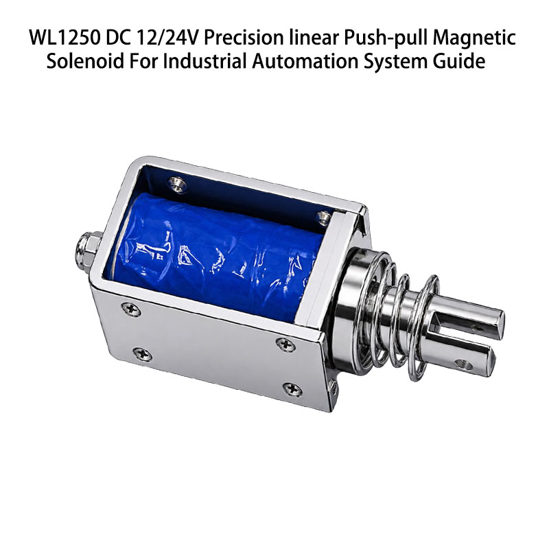
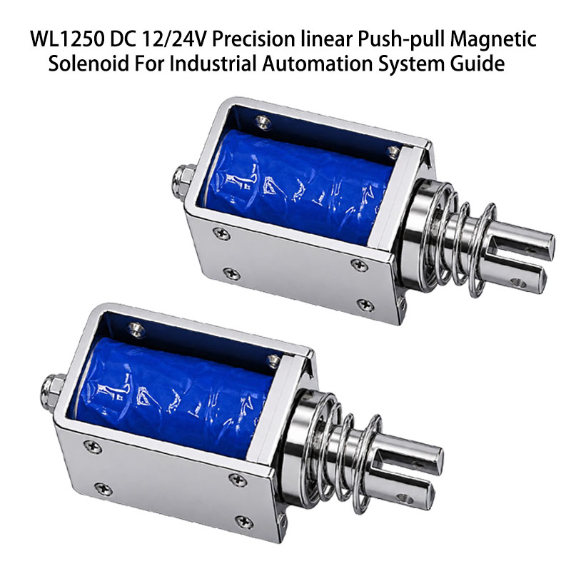
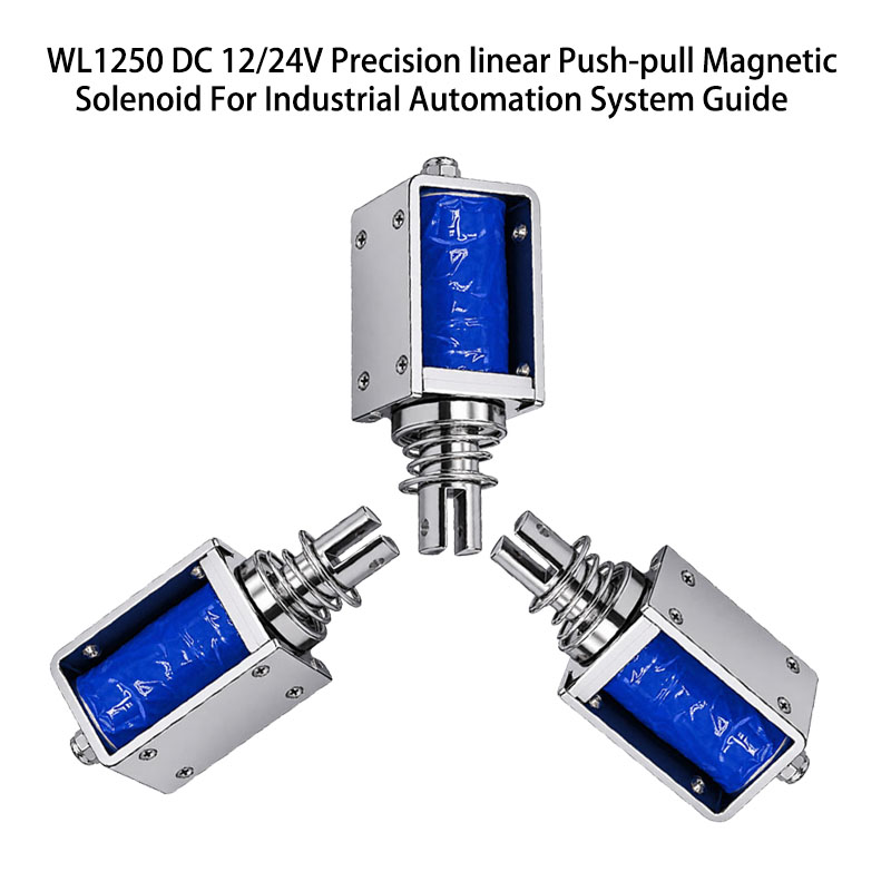
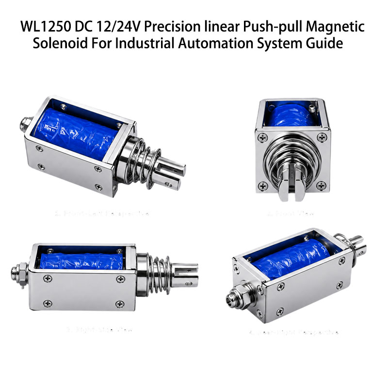
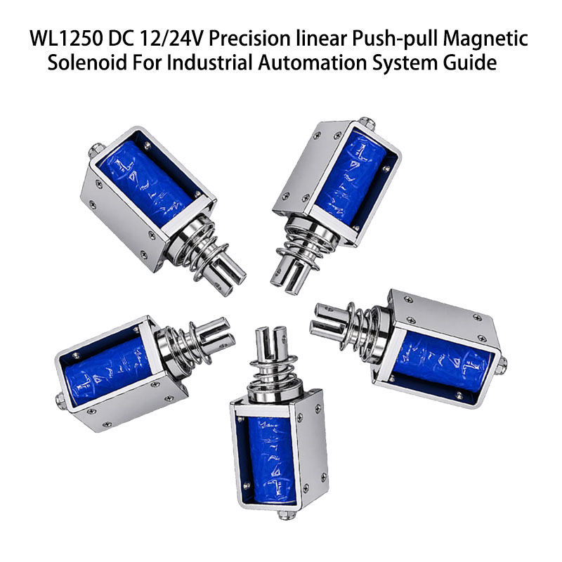
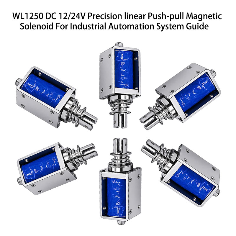
WL1250 Push-Pull Magnetic Solenoid for Industrial Automation Guide

The push-pull magnetic solenoid is a small electromagnetic actuator that generates a linear push or pull movement under electrical excitation. Due to the simplicity of the design, fast response, and electrical controllability, this type of solenoid has a lot of applications in industry.

The solenoid typically consists of the electromagnetic coil, a movable steel plunger, a housing, a spring, and a coupling mechanism. Upon energizing the coil, the magnetic field is generated, and the plunger is attracted to the position with the minimal reluctance of the magnetic circuit. The resulting motion operates locks, latches, levers, valves, gates, switches, dispensers, and other mechanical devices.

Push-pull magnetic solenoids exist in many voltages, stroke lengths, forces, duty cycles, mounting styles, and plungers. They are compact, and thus, they are very useful in cases when the installation space is limited. The engineer should select the solenoid depending on the required force, stroke, operating frequency, voltage, temperature, duty cycle, and expected service life.


Compact Push-Pull Magnetic Solenoid Product Overview

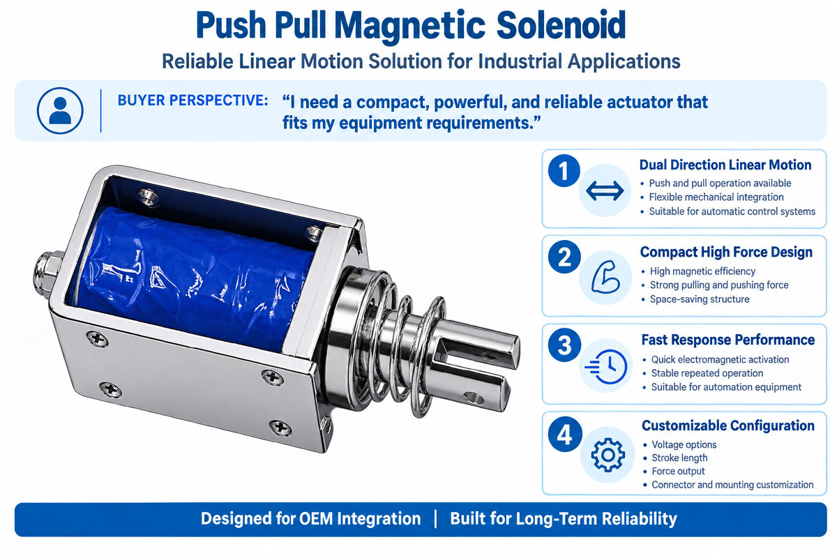
A push-pull magnetic solenoid provides electrical control of the linear actuation of industrial machines and automation systems. The simple design includes an electromagnetic coil, a magnetic frame or housing, a movable plunger, a return mechanism, and electrical leads or connectors. Various models can be supplied with push or pull output, various stroke lengths, force levels, voltages, and duty cycles. The DC voltage options can be 5 V, 12 V, 24 V, or other application-specific ratings. Custom configurations include specialized plungers, springs, mounting brackets, connectors, and housing dimensions. Always select according to actual electrical, mechanical, thermal, environmental, and lifetime requirements.

How Does a Push-Pull Magnetic Solenoid Work?

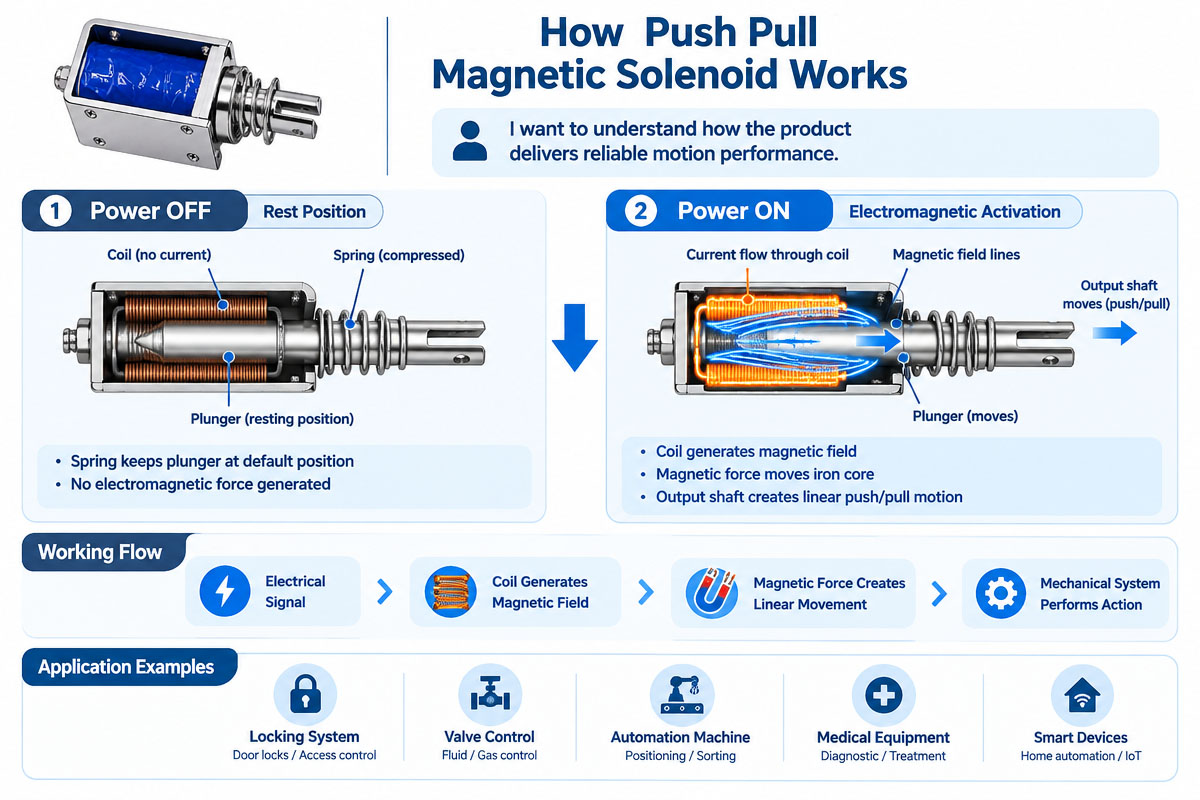
The push-pull magnetic solenoid is based on the principle of electromagnetism. The actuator comprises an electromagnetic coil consisting of an insulated copper wire wound around a magnetic path and a movable ferromagnetic plunger.

Under the voltage application, electrical current starts to flow through the winding and generates a magnetic field. This field generates a magnetic attraction and draws the plunger to the position of minimal reluctance of the magnetic circuit.

In the pull type, the plunger is attracted to the position within the energized coil or the magnetic frame.

In the push-type configuration, the same electromagnetic attraction translates into an outward movement by the plunger or a push rod mechanism.

Upon de-energization, the plunger can be drawn back to its original position by a return spring or external mechanism or gravitational force.

The force of the solenoid is non-uniform along the stroke. In many traditional designs, the force increases dramatically with the reduction of the air gap. Therefore, the engineer should evaluate the force at the working stroke and not at the advertised maximum force of the solenoid.

Push-Pull Magnetic Solenoid Features

Push-Pull Magnetic Solenoids provide fast repeatable linear motion in a small electromagnetic package. The key features include fast ON/OFF electrical control, short response time, compact design, flexible stroke selection, and various voltages. Depending on the design, they generate either a pushing or pulling mechanical motion. They can be supplied with various plungers, springs, connections, mounting holes, lead wires, and mechanical connections. Industrial versions can be designed for harsh environments and high cycle life. The key parameters for the selection are starting force, holding force, stroke, voltage, current, power consumption, duty cycle, operating temperature, and insulation class.

Compact Push-Pull Magnetic Solenoid Product Video

Compact Push-Pull Magnetic Solenoid Product Detailed Display

Push-Pull Magnetic Solenoid Technical Datasheeet

Brand Weilong Technology Model Number WL1250
Rated Voltage (V) DC 12V or 24V Rated Power (W) 8 Wโ€“30 W
Work Mode Push and Pull Holding Force (N) 100-500 Gf
Stroke (mm) 2-5 MM Customized Working Duty Continuous or intermittent
Service Life 200 Thousand Times Certification CE, RoHS, ISO9001,
Material Superior Magnet Iron Lead Wire Length (mm) 200 MM
Install Style Screw mounting hole Tolerance of Dimension ยฑ 0.1 MM
Water-proof None Insulation Class B
Hi-Pot Test AC 600V 50/60 Hz 2s Non-excitation Holding Force 0
Working Temperature -10ยฐC-100ยฐC Duty Cycle 1-100%
Thread Depth (mm) / Payment Term TT, or LC at Sight
Sample Order Yes. Warranty 1 Year
MOQ 1000 pcs Supply Ability 5000 pcs per week
Delivery Time 30 Days Port of Loading Shenzhen

Magnetic Solenoid Push vs. Pull: Which Type Should You Choose?

Magnetic Solenoid Push vs. Pull Which Type Should You Choose

In industrial automation, push-pull magnetic solenoids have become increasingly popular because of one of the main engineering requirements: conversion of the electrical signal into fast and repeatable linear movement.

Solenoids allow performing short push, pull, lock, release, switch, or positioning functions and require fewer parts than motor-driven mechanisms.

Moreover, the simplified design may decrease the size of the system.

It is easy to integrate push-pull magnetic solenoids with PLCs, relays, transistors, sensors, and other industrial automation electronics.

With their help, the controller can energize and de-energize the solenoid according to the machine logic, sensor signal, sequence, and safety conditions.

One of the most significant advantages is the flexibility of design.

The solenoids may be designed in different voltages, forces, strokes, springs, plungers, connectors, mounting and housing dimensions.

Thus, they are suitable for both standardized equipment and OEM automation projects.

However, this does not mean they are the best solution for any application.

Engineering has to take into account stroke, force, duty cycle, heating, operating frequency, noise, environment, and life.

The right selection of a push-pull magnetic solenoid allows using a compact and feasible industrial automation solution for short-stroke ON/OFF linear movement.

Push Pull Magnetic Solenoid What Type is Best for You?

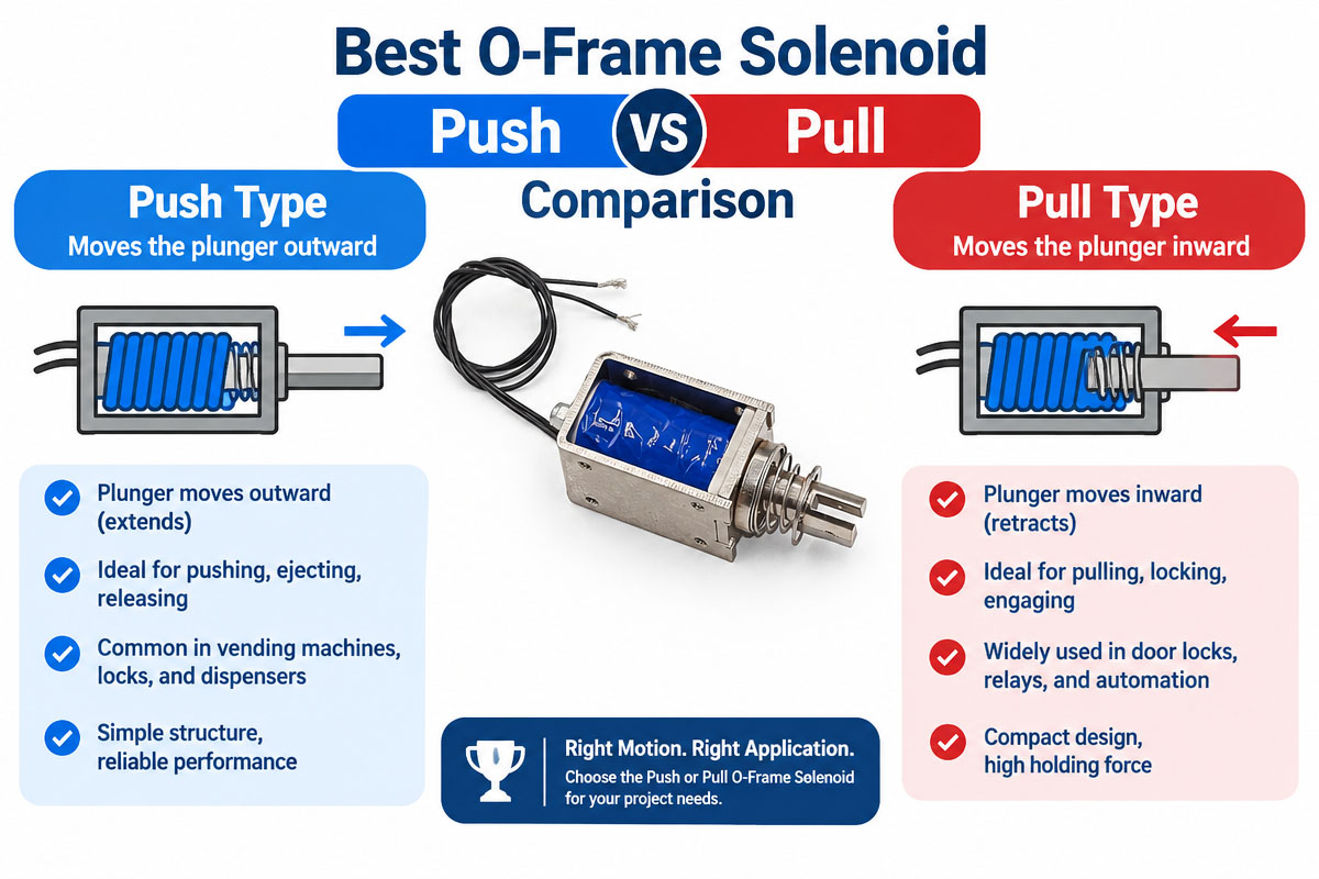
Selection of push and pull magnetic solenoids mainly depends on the direction of the desired mechanical movement, installation geometry, required force, stroke, return mechanism, and available installation space.

Although the terms “push solenoid” and “pull solenoid” may be used for different output directions, they operate in the same way.

Namely, the magnetic field of the energized coil draws the plunger into the position with low reluctance inside the magnetic circuit.

Depending on the design of the actuator, the internal attraction may result in a useful push or pull at the connection point.

What Is a Pull Solenoid?

The pull solenoid is designed in such a way that the plunger moves towards the actuator when the coil is energized.

Therefore, the external mechanism is pulled.

Such configurations are used for latches, locks, releases, valves, levers, safety devices, vending equipment, and other machinery.

The simplest mechanical configuration is provided by a pull solenoid, as some component has to be attracted by the actuator.

What Is a Push Solenoid?

The push solenoid operates in a way that converts electromagnetic movement into the pushing motion performed by the extended plunger.

Such configurations are used for ejectors, product stops, triggers, sorting mechanisms, switches, positioning devices, dispensing equipment, and other machinery, where some component has to be moved away from the actuator.

Solenoid Force Push or Pull

Do not assume that a push solenoid has inherently higher force compared to a pull solenoid. The actual performance depends on the magnetic circuit, coil design, plunger geometry, air gap, stroke, electrical input, temperature, and mechanical configuration.

The most important thing is the force at the required working stroke.

A solenoid sold with a high holding force may produce low force at the beginning of the stroke.

Therefore, engineers have to ask about or review the characteristics of force vs. stroke, rather than maximum force.

Which Type Should You Choose?

Select a pull solenoid if the load moves naturally towards the actuator: for example, when releasing the latch or pulling a lever.

If the movement has to be performed outward, like the operation of an ejector, pin, stop, or mechanical trigger, use a push solenoid.

Output direction is not the only criterion for selecting a solenoid. Other criteria are

Required force for startup and operation

Stroke length

Voltage and current

  • Duty cycle and maximum ON time
  • Operating frequency
  • Requirements for return spring
  • Installation space
  • Orientation of mounting
  • Ambient temperature

Noise and impact requirements

  • Estimated life cycle
  • Dust, moisture, vibration, and other environmental conditions

The right push-pull magnetic solenoid for industrial automation is not always the one with the highest force rating.

This is the actuator that produces the required force at the required stroke and meets the thermal, electrical, mechanical, environmental, and lifetime requirements of the application.

Where push-and-pull arrangements can perform the same task, the arrangement providing the simplest mechanical linkage, minimum side loading, and friction, fits the available installation space and provides the most positive return action should be chosen.

Properly matched push-pull magnetic solenoids can provide fast, repeatable, and reliable linear actuation for a wide spectrum of industrial automation systems.


Custom Push-Pull Magnetic Solenoid Industrial Application

WL1250 Push-Pull Magnetic Solenoid Industrial Application Guide

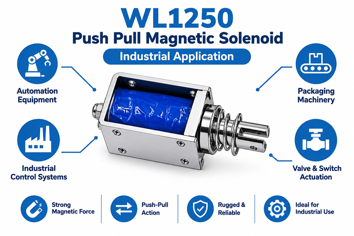
The push-pull magnetic solenoid is widely used in industrial automation, as they provide fast electrical-controlled linear motion without complex transmission systems. They are especially useful in short stroke applications needing simple ON/OFF actuation.

Factory automation solenoids can operate positioning pins, stops, gates, dividers, clamps, releases, and mechanical interlocks. They are used in packaging equipment to sort, cut, label, dispense, lock, and reject products.

Push-pull solenoids can operate in industrial control systems with various valves, switches, safety locks, latches, and mechanical triggers. They are used in vending machines, access control systems, ticket issuing machines, printers, office equipment, and automatic dispensers.

Small solenoids can release, index, push, pull, lock, or position small mechanical components with repetitive motion in robotics and automated machinery.

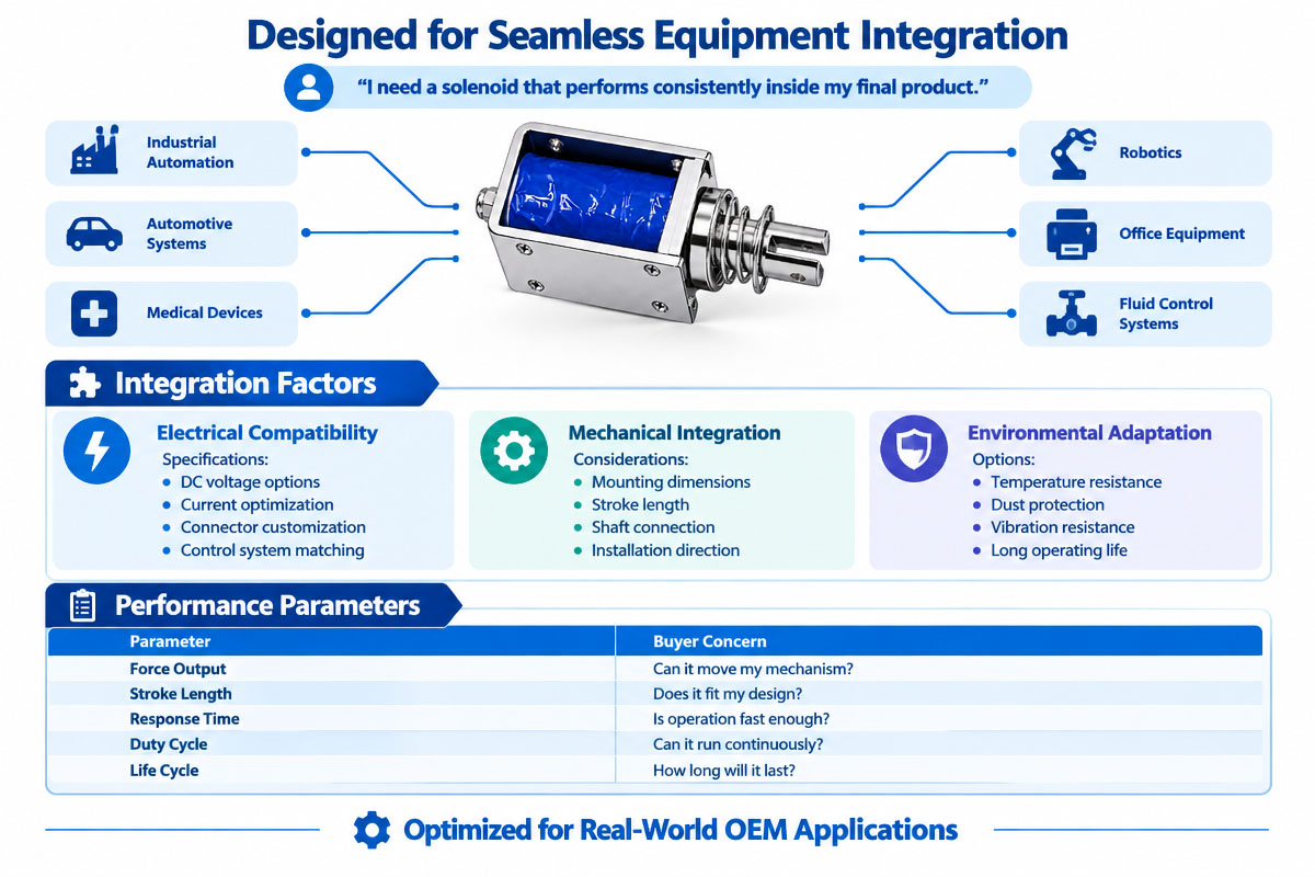
Other applications include medical equipment, laboratory instrumentation, textile machinery, agricultural equipment, home appliances, automotive subassemblies, and material handling equipment.

Depending on the application, there are specific requirements, and thus, the solenoid should be selected according to its stroke, force, response time, duty cycle, voltage, environment, mounting methods, and expected operating life.

Why Are Push-Pull Magnetic Solenoids So Common in Industrial Automation?

In industrial automation, push-pull magnetic solenoids have become increasingly popular because of one of the main engineering requirements: conversion of the electrical signal into fast and repeatable linear movement.

Solenoids allow performing short push, pull, lock, release, switch, or positioning functions and require fewer parts than motor-driven mechanisms.

Moreover, the simplified design may decrease the size of the system.

It is easy to integrate push-pull magnetic solenoids with PLCs, relays, transistors, sensors, and other industrial automation electronics.

With their help, the controller can energize and de-energize the solenoid according to the machine logic, sensor signal, sequence, and safety conditions.

One of the most significant advantages is the flexibility of design.

The solenoids may be designed in different voltages, forces, strokes, springs, plungers, connectors, and mounting and housing dimensions.

Thus, they are suitable for both standardized equipment and OEM automation projects.

However, this does not mean they are the best solution for any application.

Engineering has to take into account stroke, force, duty cycle, heating, operating frequency, noise, environment, and life.

The right selection of a push-pull magnetic solenoid allows using a compact and feasible industrial automation solution for short-stroke ON/OFF linear movement.


Custom Push-Pull Magnetic Solenoid Advantage and Disadvantage

Push Pull Magnetic Solenoid Advantage and Disadvantage

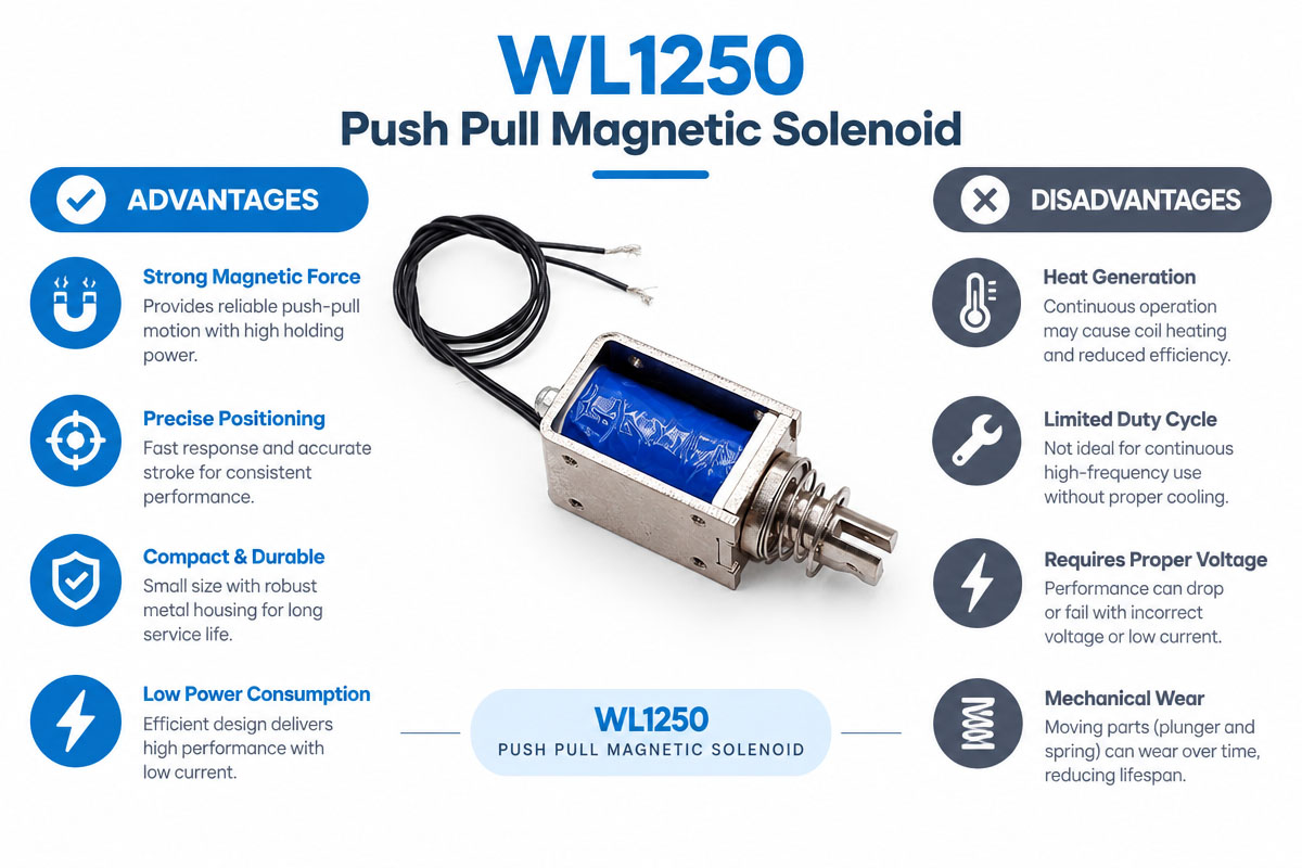
Advantage of Push-Pull Magnetic Solenoid

Push-pull magnetic solenoids are good choices for industrial automation due to several reasons. They are rather simple in design and can directly transform the electrical command into the fast linear motion. Due to their small size, they can be installed in the equipment where space is limited. Simple ON/OFF control makes the interfacing with relays, transistors, PLC-controlled circuits, and electronic controllers easier.

They provide a good force, repeatable operation, and fast response at short strokes. Solenoids can also be customized for many OEM applications with specialized plunger shapes, springs, voltages, connectors, mounting features, and housings.

Disadvantage of Push-Pull Magnetic Solenoid

However, the solenoids have their limitations. The force is highly dependent on the stroke, and long stroke applications may require larger actuators or alternative technologies. The continuous energization generates a lot of heat and increases energy consumption. The impact at the end of the stroke may also cause the noise and mechanical wear.

Solenoids are generally preferable in the short discrete motions than in multi-position motion control. Applications requiring motors, voice coil actuators, pneumatic cylinders, or other linear actuators may be better served with long stroke, controlled speed, precise positioning, or continuous proportional motion.

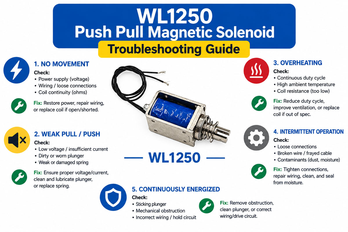
Push-Pull Magnetic Solenoid Troubleshooting Giode

Custom Push-Pull Magnetic Solenoid Troubleshooting Guide

Troubleshooting a push-pull magnetic solenoid starts with verifying if the power supply is correct. It is necessary to measure the voltage at the terminals of the solenoid when the coil is energized to ensure it equals the rated voltage.

A small power supply, bad wiring or connection, or voltage drop may lead to insufficient operating force.

The energization of the coil without moving the plunger is a sign that there are problems with the mechanical load: high friction, misalignment, side loading, contamination, too high return spring force, or long stroke.

A hot push-pull magnetic solenoid may be a consequence of incorrect voltage, ON time, switching frequency, ambient temperature, or wrong duty cycle.

In this case, the reason for overheating is over-energization of the device.

For insufficient operating force, it is necessary to make sure the required force is calculated at the correct stroke. An increase in air gap leads to the reduction of the magnetic force.

Noises may indicate loose components and high impact on the plunger, return spring, mounting, end stops, and the attached mechanism.

Intermittent operation of the solenoid can be a result of loose wiring, voltage instability, overheating, damaged insulation, or a faulty controller.

Electrical, thermal, and mechanical reasons should be excluded before the solenoid replacement. Testing is done without excessive loading of the actuator.

Custom Push-Pull Magnetic Solenoid FQQs

1. How to Select the Right Push-Pull Magnetic Solenoid?

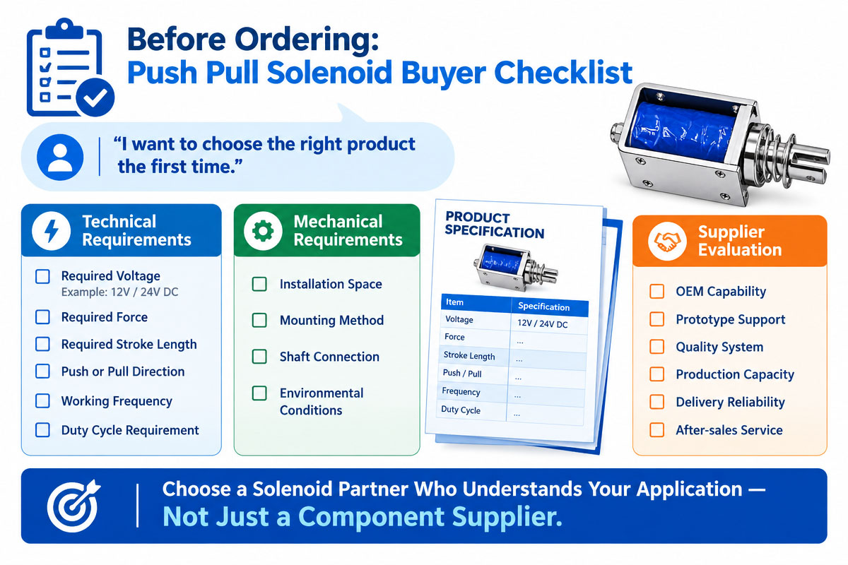
To select the push-pull magnetic solenoid, buyers should start from the required force, stroke length, voltage, duty cycle, installation space, and operating frequency.

In addition, ambient temperature, return method, mounting dimensions, and electrical connections should also be considered.

The most important thing is to verify the force that the solenoid provides at the actual working stroke, rather than comparing maximum force ratings.

For OEM projects, it is helpful to inform the manufacturer of detailed operating conditions of the solenoid.

2. What Voltage Do I Need for a Push Pull Solenoid?

Push-pull magnetic solenoids can be engineered in various voltages. 12 VDC and 24 VDC are usual for industrial applications.

Other voltages may also be available. It is necessary to select the voltage compatible with the power system of the machine.

The power source should be able to provide sufficient current when the actuator is on.

Wrong voltage may lead to weak power, overheating, and damage of the coil.


3. How Strong Is a Push-Pull Magnetic Solenoid?

The force of the solenoid is determined by the coil design, electrical power, size of the plunger, magnetic circuit, stroke, air gap, and temperature.

As the solenoid force usually is a function of plunger position, the buyers should not rely only on maximum or holding force specifications.

It is necessary to ask the supplier for force data at the required stroke and voltages of operation.

The best way to identify the suitable model is to provide the supplier with minimum required force and stroke.

4. Can a Push-Pull Magnetic Solenoid Work Continuously?

Only the solenoid specifically designed and rated for continuous operation may work continuously.

Some of the solenoids may be used only intermittently and will overheat if left on for too long.

Before purchasing the solenoid, it is necessary to specify the maximum ON time, OFF time, operating frequency, and ambient temperature.

In this way, the manufacturer may estimate the necessary design and duty cycle of the coil.

The thermal performance of high-frequency automation equipment should be estimated in the working conditions.


5. Are Push-Pull Magnetic Solenoids Suitable for OEM Projects?

Yes. Push-pull magnetic solenoids are often customized for OEM and industrial automation applications.

Customization may involve the changes in voltage, coil resistance, force, stroke, plunger shape, return spring, mounting holes, lead wires, connectors, brackets, housing dimensions, and mechanical interfaces.

If requesting a customized solution, the buyer should provide:

Drawings

Dimensional limitations

Electrical requirements

Load conditions

Operating cycle

Environmental requirements

Expected annual quantity

6. What Information Should I Offer When Requesting a Quotation?

Please provide as much information about your application as possible to obtain a precise quotation and product recommendation.

Important specifications are

Operating voltage

Required force

Stroke length

Duty cycle

ON/OFF time

Operating frequency

Installation dimensions

Mounting method

Ambient temperature

Expected quantity

For a custom project, it is especially important to provide drawings or 3D models.

Buyers should also specify connector, wire-length, spring, environmental, testing, certification, packaging, and service-life requirements, where applicable.


7. How Can I Test a Push-Pull Solenoid Sample Before Placing a Bulk Order?

It is necessary to test the sample under conditions as close to the final application as possible.

Tests should include starting force, full stroke, response time, return action, coil temperature, operating noise, current draw, and mechanical fit.

Just testing the solenoid a couple of times is not enough; the repeated-cycle test should be performed at the intended voltage and duty cycle.

It is necessary to consider the temperature rise, life-cycle performance, voltage variation, and mechanical wear and operation at the minimum and maximum ambient temperatures of the application.

8. What to Look for In Selection of a Push-Pull Solenoid Supplier?

Buyers should not focus on unit price only.

It is necessary to make sure the supplier can provide technical specifications, force vs. stroke, electrical data, dimensional drawings, material information, duty-cycle information, and sample support.

For OEM projects, it is necessary to evaluate the capability of the supplier in customization, engineering support, quality control, capacity for required volumes with acceptable lead times and traceability.

Buyers should also specify applicable certifications, inspection standards, warranty terms, minimum order quantity, tooling costs and delivery requirements before placing a production order.

How to Select a Push-Pull Magnetic Solenoid

The selection of the appropriate push-pull magnetic solenoid is not only a question of voltage and size. The actuator should provide sufficient force for the required working stroke but should not exceed acceptable electrical and thermal limitations.

First, estimate the stroke required. Estimate the distance the plunger travels to operate the mechanism. Don’t make the stroke longer than it should be, as the electromagnetic force falls off with increasing initial air gap.

Then, estimate the force at the actual stroke position. Then, add friction, spring resistance, gravity, mechanical load, and an appropriate engineering safety margin. Don’t select the solenoid based on the maximum or holding force only.

Also, check the operating voltage and the available current. The DC voltage is usually 12 V or 24 V, but it depends on the control system and power supply.

Duty cycle is also an important parameter. A solenoid operated for a fraction of a second each minute has very different thermal requirements than the one energized for long periods. High ON time can increase coil temperature and decrease insulation life.

Also, consider the response time and the operating frequency. In the case of high-speed automation, you may need low moving mass, proper spring force, optimal stroke, and a suitable driver circuit.

Also, consider the operating environment, including ambient temperature, moisture, dust, vibration, shock, corrosion, and possible contact with oils or chemicals.

Finally, check the installation space, plunger orientation, return mechanism, electrical connection, noise requirements, expected cycle life, and mechanical tolerances.

For the OEM project, provide the solenoid manufacturer with the following: voltage, stroke, required force vs. position, ON/OFF time, frequency of operation, ambient temperature, available dimensions, mounting requirements, load characteristics, and target service life. With such information you can select or modify your solenoid more accurately.

How to Avoid Common Mistakes in Designing a Push-Pull Magnetic Solenoid

The first mistake in the design of a push-pull solenoid is to select a solenoid based on the maximum force, without estimating the force at the desired stroke. The force of the solenoid varies with the plunger position, and thus, you should always check the force vs. stroke graph.

Second, don’t ignore the duty cycle. The continuous energization of the intermittent-duty solenoid can result in the high coil temperature, degradation of insulation, poor performance, or early failure.

Don’t use long strokes. In general, the increase of the air gap requires more magnetic energy and can reduce the starting force.

You should also pay attention to the return spring. A spring that is too strong reduces the usable output force, and a spring that is too weak may fail to return the mechanism.

Don’t forget about the voltage tolerance and power-supply capability. The current and operating force can be decreased due to voltage drops in wiring, switching devices, or undersized power supplies.

The alignment of the mechanics is also an important factor. Side loading, misaligned linkages, excess friction, and contamination of the plunger surfaces can prevent smooth motion.

In addition, the engineer should consider the coil heating, ventilation, ambient temperature, switching frequency, flyback protection, mounting tolerances, noise, vibration, and expected cycle life in the design stage.

Above all, the solenoid should be tested under realistic load, temperature, voltage, stroke, orientation, and duty cycle conditions before the final design is completed.

Get A Free Quote Now

Contact Form

Related Products

Related News

Scroll to Top

Get A Free Quote Now !

Contact Form
If you have any questions, please do not hesitate to contact us.
Weilong Solenoid Company Culture