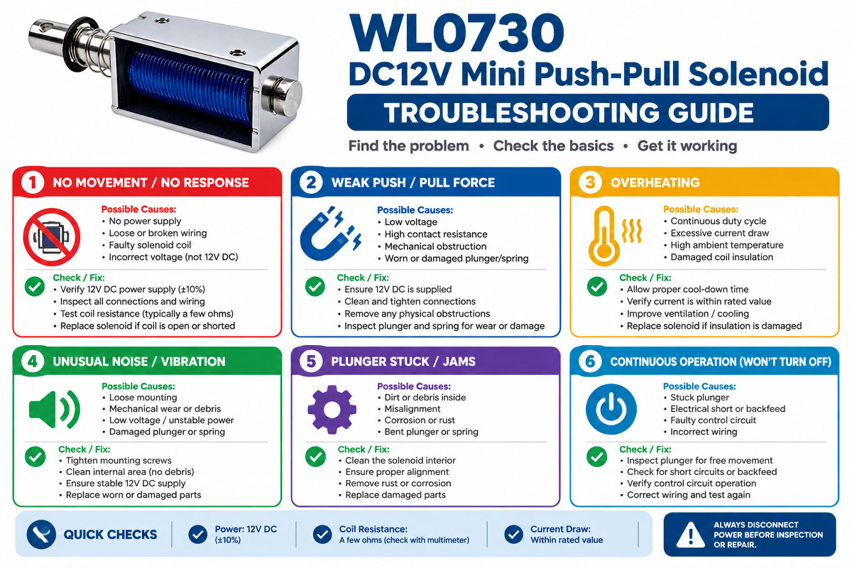
How to Select a 12V Mini Push Pull Solenoid
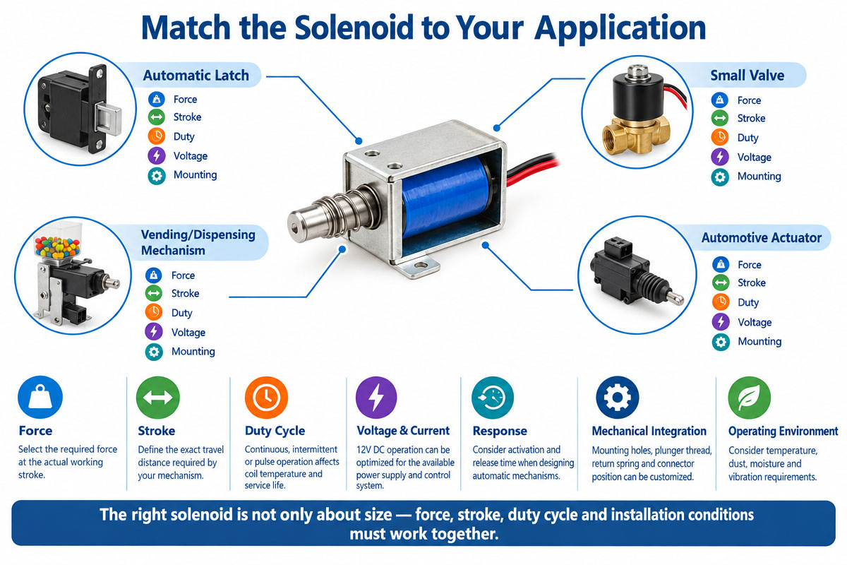
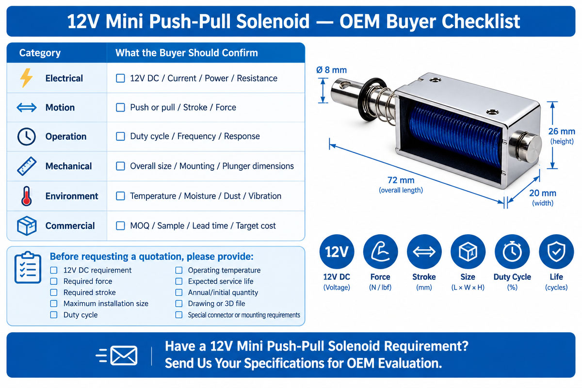
Selection of a 12V mini push-pull solenoid should be based on the mechanical requirements, not only the voltage.
1. Necessary Force Discovery
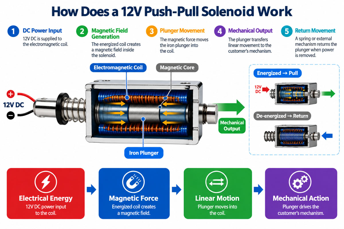
Find out the actual force required to move the mechanism. Take into account friction, spring force, gravity, mechanical resistance, and some safety margin. The solenoid force changes generally depending on the plunger position. Also, define the point where the force is required during the stroke.
2. Storke Definition
Define the travel distance of the plunger. 2 mm stroke and 10 mm stroke may require totally different magnetic and mechanical designs.
3. Direction of Motion Definition
Determine whether the application requires:
pull action
push action
push-pull movement
spring back
return mechanism external
The mechanical setup should be similar to the customer’s mechanism.
4. Checking the 12V mini push pull solenoid electrical system
Check that your power supply is capable of delivering the required current. Check
rated voltage
resistance of coil
existing
power consumption
voltage tolerance
controller capacity
5. Duty Cycle Evaluation of 12V mini push pull solenoid
A solenoid energized for short pulses has different thermal requirements than the one energized continuously. Define the required duty cycle, frequency of activation, and energize time.
6. Installation Space Checking
The maximum permissible length, width, and height. Also, check mounting holes, plunger diameter, shaft/thread dimensions, and connector location.
7. Operating Environment Analysis
Evaluate exposure to temperature, humidity, dust, vibration, and corrosion for industrial applications. If operating outdoors or in wet conditions, specify the actual protection requirements; don’t assume a standard solenoid is waterproof.
8. Service Life Definition
Estimate the number of cycles of operation over the expected product life. Additional materials, bearings, springs, or mechanical structures may be needed for higher cycle demands.
9. Response Requirements of 12v mini push pull solenoid Assessment
If the solenoid is to be used for high-speed automation, specify the required on and off times. Real system response may be affected by the controller design and mechanical load.
10. Prototype Testing Request
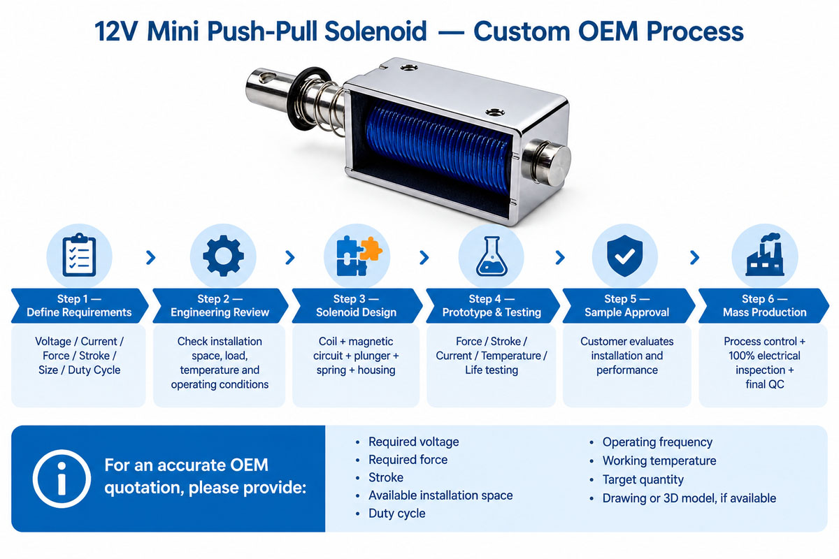
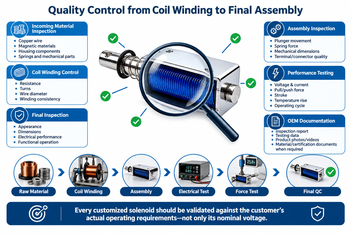
Test the solenoid with the real load, stroke, voltage, temperature, and duty cycle before it goes into mass production. “This is especially relevant to custom OEM designs.”
Tips to Avoid Common Mistakes Designing a 12V Mini Push Pull Solenoid
Error 1: Choice Only By Voltage
A 12V rating doesn’t mean that the solenoid is capable of generating the required force. Force, stroke, and voltage are always specified together.
Error 2: Disregard of Force at End of Stroke
The force of the solenoid varies considerably when the plunger moves. State the force required at the real working position.
Mistake 3: Incorrect Duty Cycle
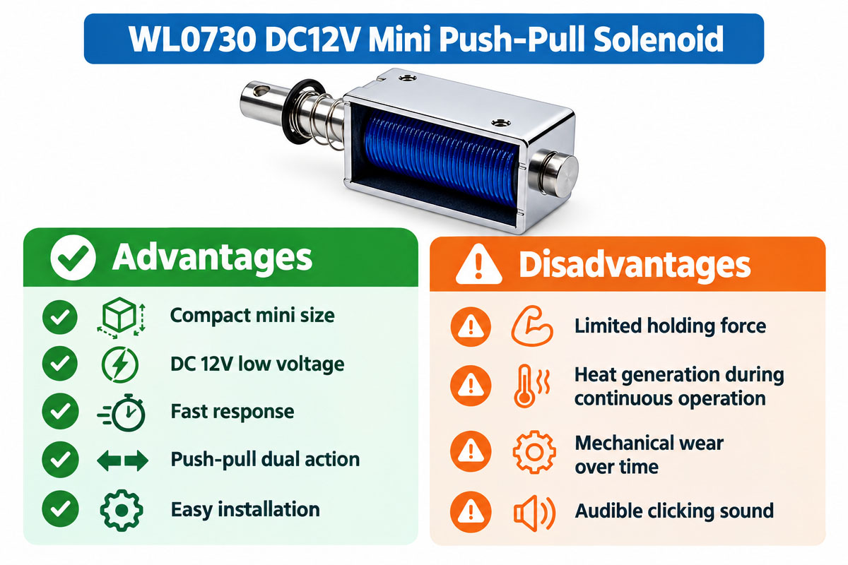
A coil designed for intermittent duty may overheat when held energized. Confirm energize time, cycle rate, and duty cycle.
Mistake 4: Ignoring the Return Force
The solenoid has to overcome not only the external load but also the spring force, friction, and other mechanical resistance.
Error 5: No More Installation Tolerance
Don’t design the system to nominal solenoid dimensions only. Provide enough space for mounting, wiring, motion, and manufacturing tolerances.
Error 6: Ignoring Heat
The resistance, current, and performance are affected by the coil temperature. Evaluate thermal conditions under a real operating cycle.
Error 7: Use of Stroke That Is Too Long
A longer stroke is not necessarily better. Use the shortest stroke possible that will satisfy the real requirement of the mechanism.
Error #8: Missing Prototyping Testing
A solenoid that operates on a test bench can behave differently when connected to the actual mechanism. Always test the complete system.