
Skip image slider
Solenoid Lock Actuator for Industrial Access Safety Solutions
Custom Solenoid Lock Actuator for OEM Applications
Industrial Solenoid Lock Actuator Manufacturer Guide
How a Solenoid Lock Actuator Works in Safety Systems
Reliable Solenoid Lock Actuator for Access Control
Compact Solenoid Lock Actuator for Space-Saving Design

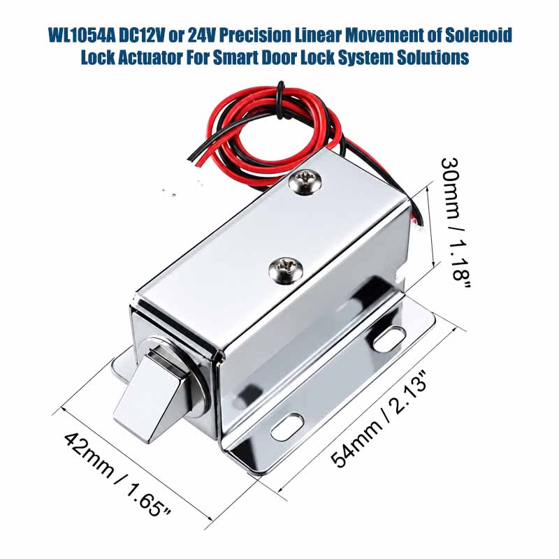
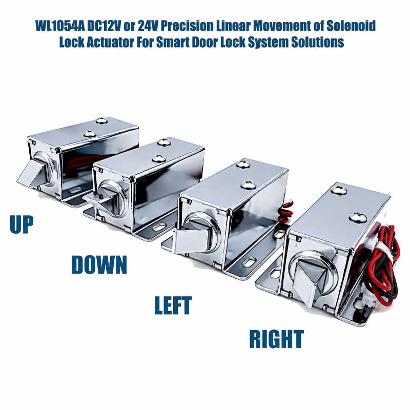
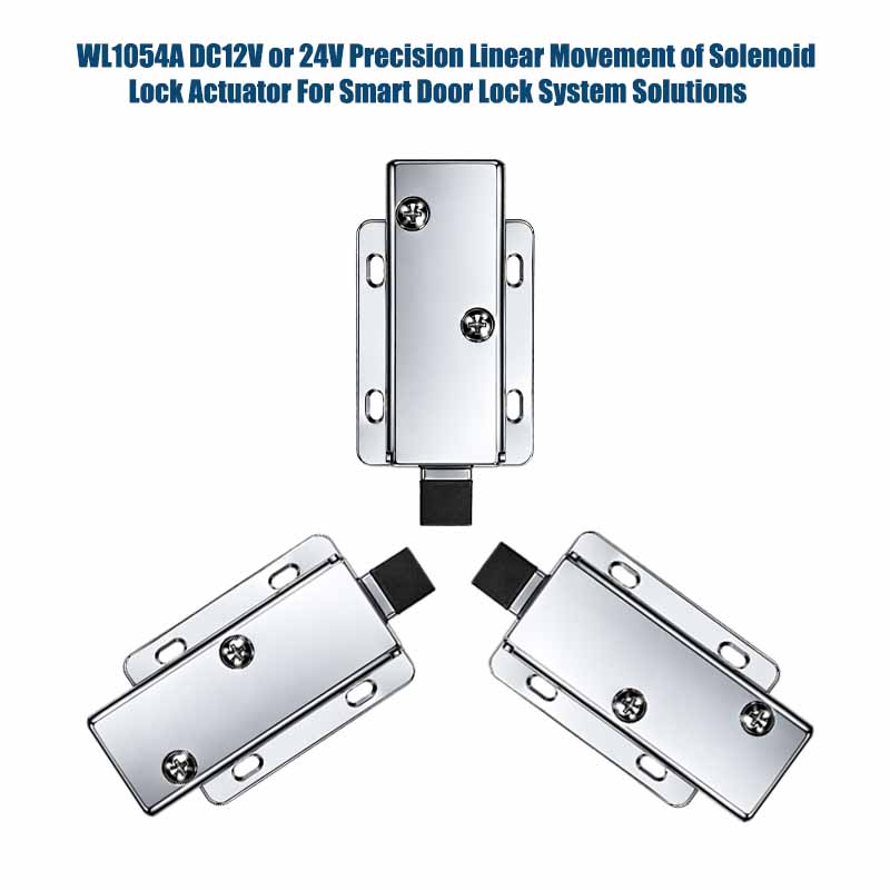
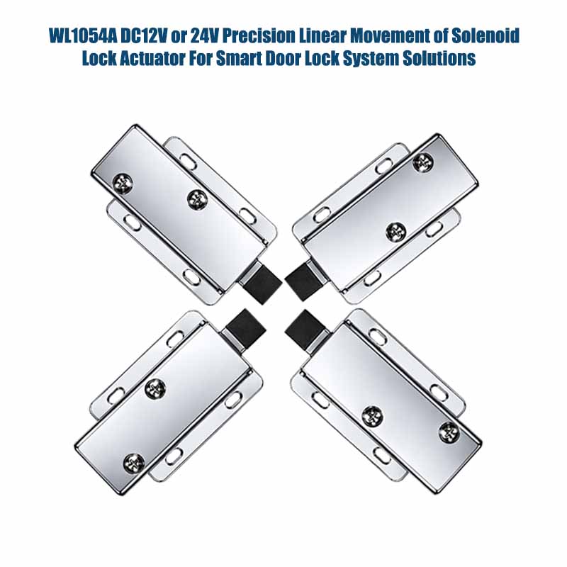
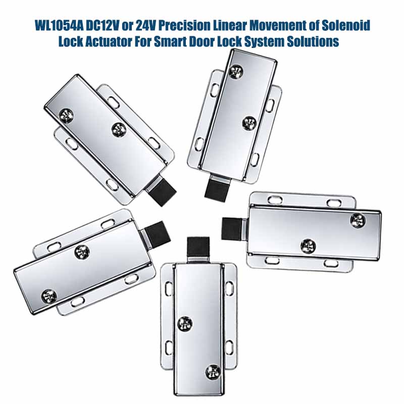
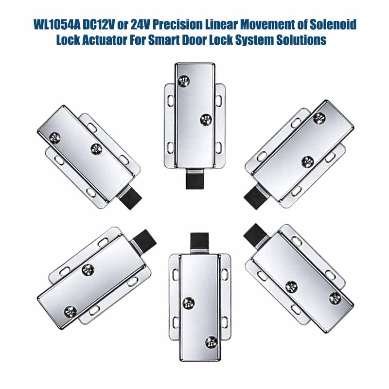
WL1054A Solenoid Lock Actuator for Smart Door Lock System Solutions

A solenoid lock actuator is an electromechanical device that can be used for actuating locking and unlocking operations in industrial equipment, electronic cabinets, smart locks, and automated access control systems. The actuator converts electrical energy into mechanical motion to move a plunger or armature for actuation of a bolt, latch, pin, or release mechanism.

There can be spring return, push-pull, latching, or other types of solenoids that lock actuators, depending on your needs. Engineers determine the required operating voltage, stroke length, force, time delay, duty cycle, mounting dimensions, and connector layout to fit your design.

While choosing the actuator for your industrial access safety system, it is necessary to think of mechanical loads, electrical power sources, working conditions, operation frequency, and locking status under power failure. The right integrated solenoid actuator will give you a compact design and reliable operation.

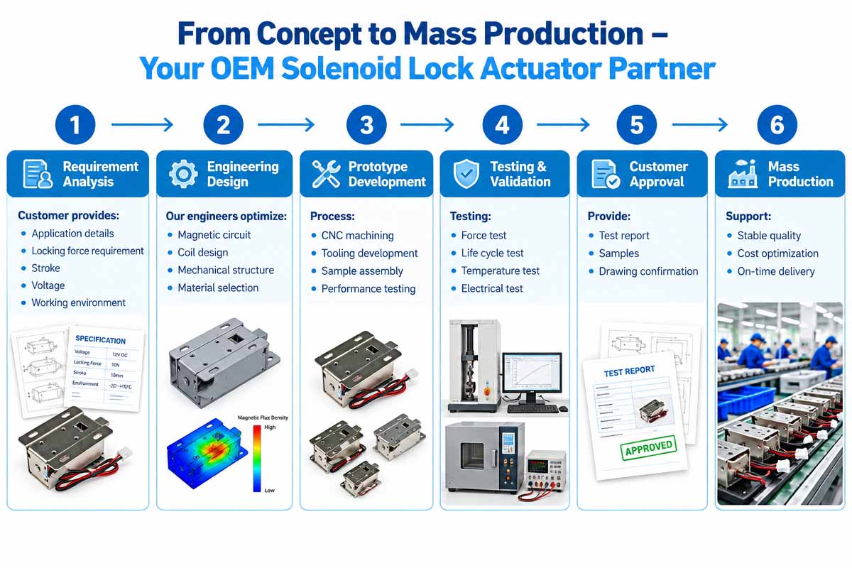
Weilong Intelligent Technology offers OEM customization and collaboration in the engineering of electromagnetic components, helping customers with the development of their systems for specified mechanical, electrical, and manufacturing needs.

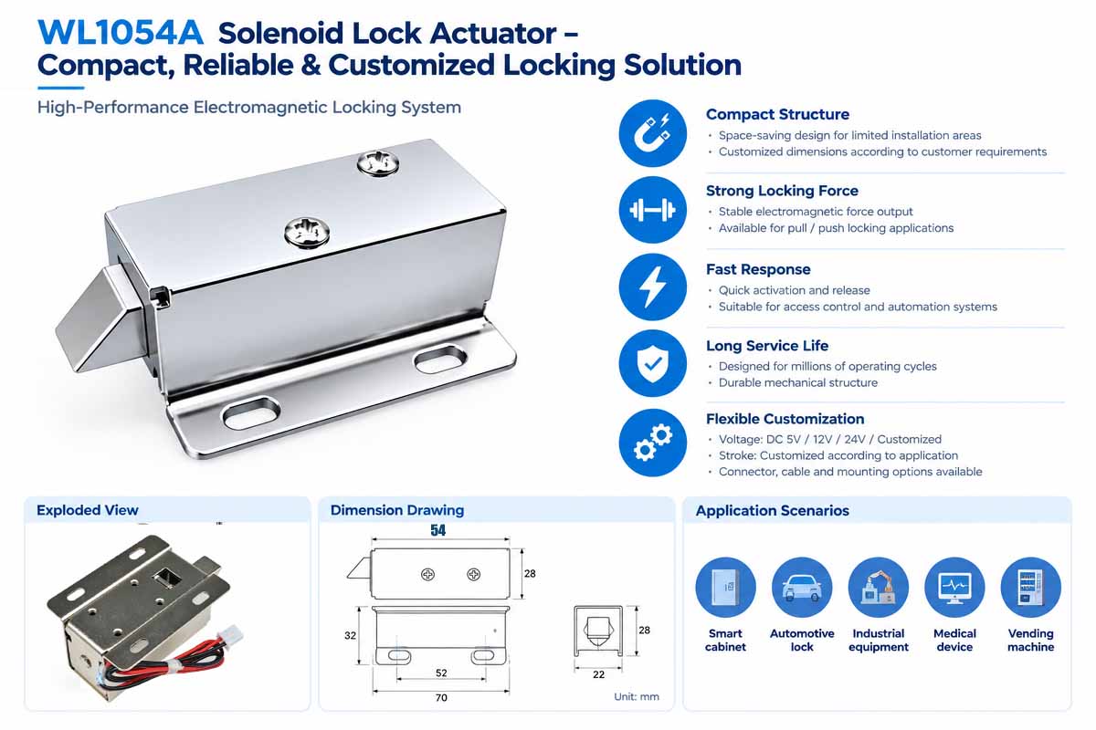
Custom Solenoid Lock Actuator Product Overview

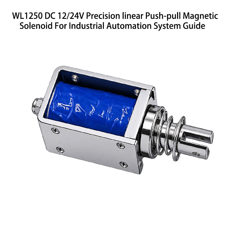
A solenoid lock actuator is an electromagnetic device providing controlled mechanical movement for locking and access control applications. Usually solenoid lock actuators consist of the coil, magnetic circuit, movable plunger, housing, and, if necessary, return spring or latch. An application of the electrical signal operates a connected latch, pin, bolt, or release mechanism.

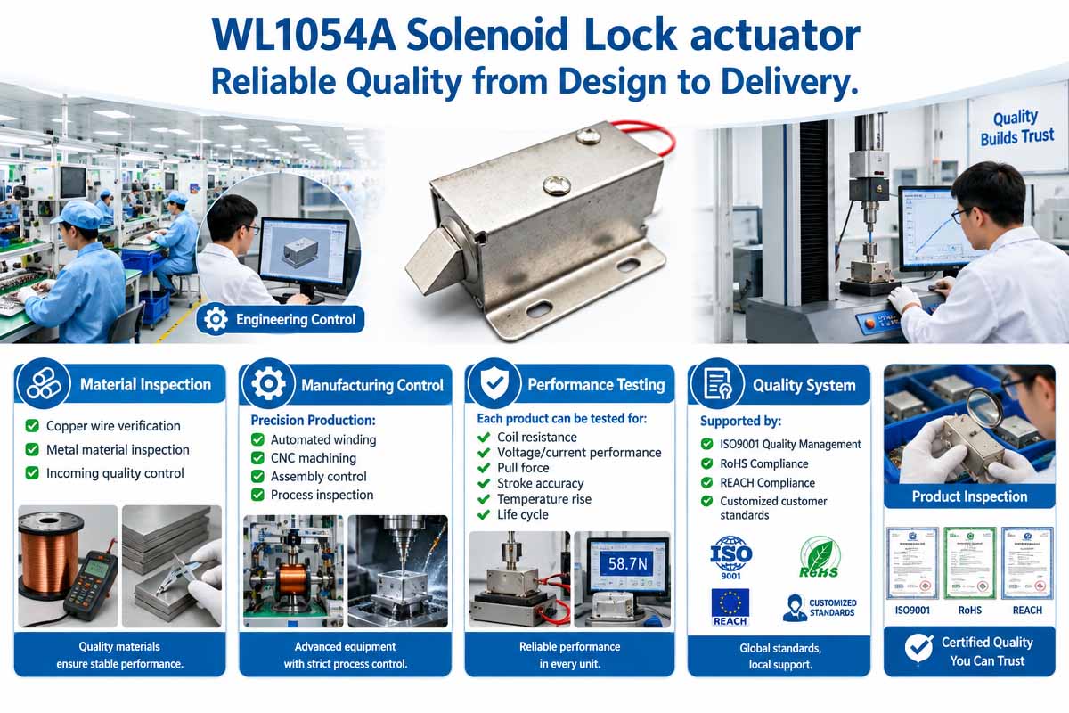
Depending on the force, stroke, voltage, mounting, duty cycle, and other parameters, there are many configurations of solenoid lock actuators. The actuator can be tailored to meet the requirements of the electrical and mechanical interface of the host equipment for OEM projects. The performance of the actuator should be tested.

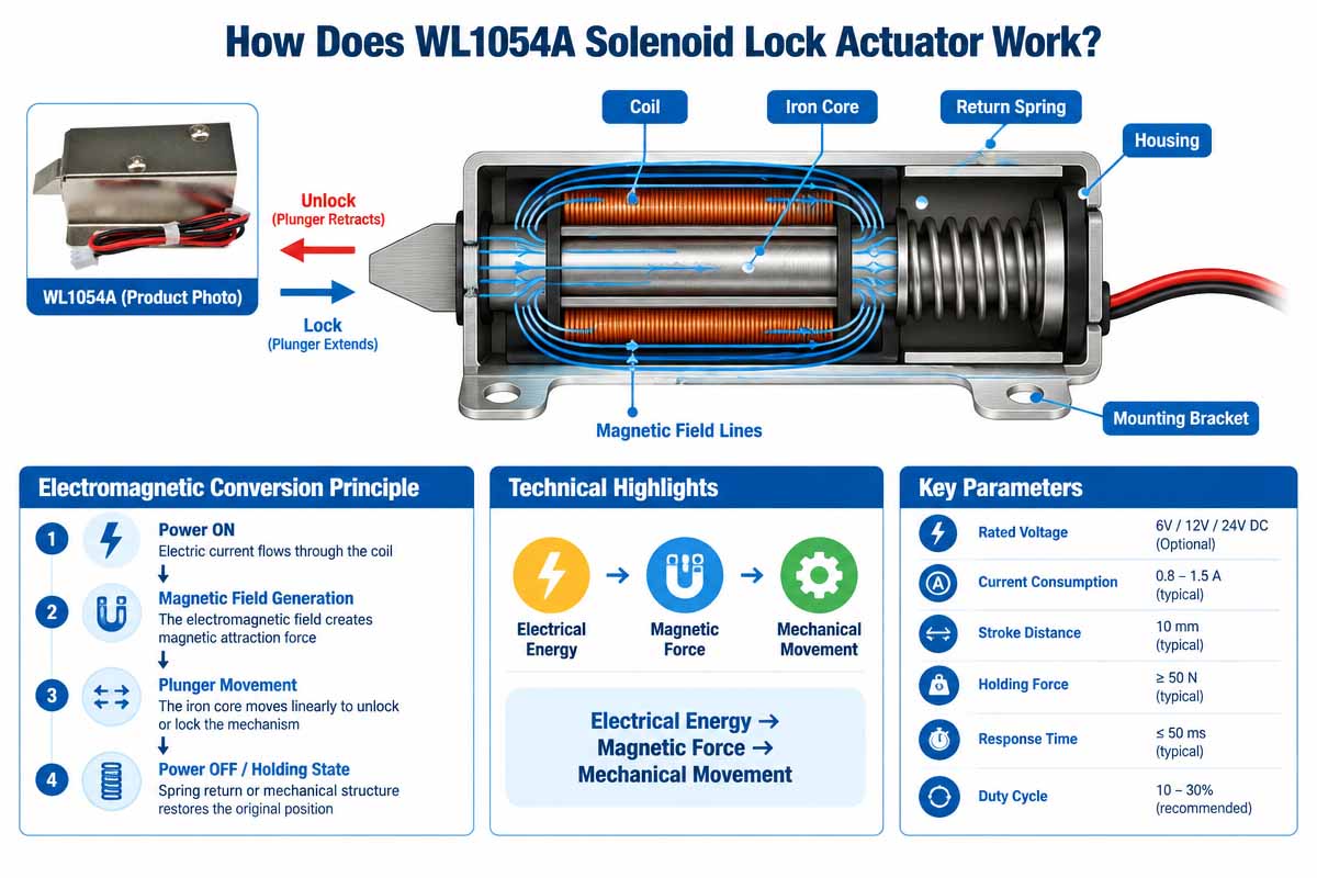
How Does a Solenoid Lock Actuator Work?

The function of a solenoid lock actuator is determined by the laws of electromagnetic induction and the conversion of electrical energy into mechanical motion.

Step 1: Apply voltage to the device.

Electrical current passes through the winding when the control circuit sends the required voltage to the solenoid winding.

The magnetic field and the form of the current wave depend on the resistance and inductance of the coil, the applied voltage, and the control algorithm.

Step 2: Create electromagnetic field.

An energized solenoid winding creates a magnetic field, which acts upon ferromagnetic components of the actuator.

This magnetic field creates force acting on a plunger to reduce its reluctance.

Step 3: Plunger moves.

The plunger makes the movement along the stroke, performing a mechanical action on the locking mechanism.

According to your design:

The plunger will pull the lock pin.

Unlock some mechanism.

Lock some locking mechanism.

Actuate the release bar,

Move a pin or a linkage.

The solenoid lock actuator doesn’t lock the mechanical assembly; only the mechanical assembly performs this action.

Step 4: The locking mechanism changes its state.

During the motion the state of the locking components connected with the actuator changes.

Spring return designs return to their original state after power loss. Latching designs can keep the last state without constant power feeding, depending on magnetic and mechanical characteristics.

Step 5: The system comes to the required state.

The control system defines when the actuator turns ON or OFF.

In the case of an industrial safety system, engineers should define the required state of the actuator under normal conditions, power loss, emergency stop, and control system malfunctions.

Important engineering note: the solenoid lock actuator in itself doesn’t provide a safe lock mechanism. In the case of hazardous machinery, it could be necessary to add other safety features according to risk assessment.

What Are the Main Features of a Solenoid Lock Actuator?

Solenoid lock actuators feature compact construction and electromagnetic action, fast response, and flexible mechanical action. They are defined by adjustable stroke length, actuation force, operating voltage, mounting dimensions, and electrical connector. Depending on the design, actuators can make push, pull, spring return, and latching actions. Industrial models can be made for continuous operation, for specific duty cycles, and for operating temperature ranges.

Custom housing and mounting systems facilitate the assembly of the cabinet, access panel, or automated equipment. Performance of an actuator is defined by the design of the coil, magnetic and mechanical systems, air gap, mechanical load, and conditions of the power feeding. Proper specification and tests will help achieve repeatable operation and adequate temperature rise and service life of the product.

Custom Solenoid Lock Actuator Product Video

Custom Solenoid Lock Actuator Product Detailed Display

Custom Solenoid Lock Actuator Technical Data Sheet

Brand Weilong Technology Model Number WL1054A
Rated Voltage (V) DC 6V, 12V, or 24V Rated Power (W) 8โ€“20 W
Work Model PULL Type Holding Force (N) 0.5โ€“1 N
Stroke (mm) 5-10 MM Reset Time(s) 1 S
Service Life 300 Thousand Times Certification CE, RoHS, ISO9001,
Material Carbon Steel Housing with Zinc-Plated Coating Lead Wire Length (mm) 200
Install Style Adjustable Screw Tolerance of Dimension ยฑ 0.1 MM
Water-proof None Insulation Class F 155 Cel. Degree
Hi-Pot Test AC 600V 50/60 Hz 2s Non-excitation Holding Force 0
Working Temperature -10ยฐC-100ยฐC Duty Cycle 1-100%
Thread Depth (mm) / Payment Term TT, or LC at Sight
Sample Order Yes. Warranty 1 Year
MOQ 500 pcs Supply Ability 5000 pcs per week
Delivery Time 30 Days Port of Loading Shenzhen

Rotary Solenoid Lock vs. Solenoid Lock Actuatorโ€”Which One Is Better?

Solenoid Lock Actuator vs Rotary Solenoid Lock - Which should you choose

Introduction:

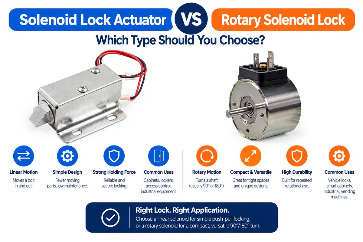
Depending on the required movement, the available installation space, the mechanical load, the control method, and the locking architecture, you can choose between a solenoid lock actuator or a rotary solenoid lock.

Both devices use the electromagnetic force to produce mechanical motion. However, the typical linear solenoid produces a motion of the plunger in a straight line, while the rotary solenoid produces the motion about the axis.

Understanding the difference between these two can help OEM engineers select an actuator that will meet the requirements of the application.

1. Work Principle and Motion

Solenoid Lock Actuator

The linear solenoid lock actuator is typically a device that converts electrical energy into linear motion. When powered, the coil pulls the plunger in or pushes it out depending on the design.

This motion can operate a locking pin, release a latch, pull back a bolt, or operate a linkage.

The locking mechanisms with a defined straight stroke are particularly well served by linear solenoids.

Rotary Solenoid Locks

The rotary solenoid converts electrical energy into angular motion. Depending on the design, the rotor or shaft rotates through a certain angle upon energization.

The motion can operate a rotatable latch, turn a cam, or operate the mechanism requiring an angular displacement.

The rotary solenoids are useful when the host equipment requires the rotational, rather than linear, action.

Think of the difference as Linear solenoids provide straight line travel. Rotary solenoids provide angular travel. Neither type is inherently more secure or reliable; it is the complete mechanical design that determines those characteristics.

2. Structural Design and Install

The linear solenoid actuator typically consists of the coil, magnetic circuit, movable plunger, and housing. It may have a return spring to return the plunger after power removal.

The rotary solenoid provides the mechanism for angular displacement. Depending on the construction, the assembly may consist of the rotor, magnetic components, return mechanism, and shaft.

Which one is better depends on the space available for installation and the amount of motion required by the lock.

If the locking pin or latch moves in a straight line along the axis of the plunger, the linear actuator might be more appropriate. If the design already has the cam or rotating locking element, the rotary solenoid can simplify the mechanism.

Before making the decision, engineers have to compare the full assembly dimensions, mounting points, clearances, transmission components, and service access.

3. Force, Torque, and Mechanical Stress

The linear solenoid actuators are usually rated in terms of force versus stroke, i.e., newtons at a specified position of the plunger.

The rotary solenoids are usually rated in terms of torque across the angular displacement.

These specifications are not directly comparable without taking into account the mechanism of how one type of the motion is converted into another.

For example, the linear solenoid may drive the rotary latch via linkage. On the other hand, the rotary solenoid can operate the linear bolt with the help of a cam.

The result depends on the geometry, the friction, the mechanical advantage, and the efficiency of the mechanism.

Selection tip: Specify the actual force or torque required at the lock, not just the nominal output of the actuator.

4. Electric Power and Duty Cycle

Each type requires the electrical supply suitable to the coil and control circuit.

The key parameters are

Rated voltage and permissible voltage range.

Current draw and resistance of the coil.

Activation time and frequency of operation.

Temperature rise and duty cycle.

Response time.

Power consumption in the default and activated modes.

The standard linear and rotary solenoids may heat up when energized. The continuous duty operation has to be confirmed in writing and cannot be assumed.

If you are interested in the battery-powered smart locks, consider whether the latching mechanism might eliminate the need for constant coil power. The actual energy savings depend on the whole operating cycle and the power consumption of the control electronics.

5. Reliability & Maintenance

The reliability of either actuator depends on the coil design, materials, operating temperature, mechanical loading, quality of manufacture, and integration.

The linear designs can suffer from plunger wear, guide friction, spring fatigue, or sticking due to contamination.

The shaft or bearing wear, angular position variation, and mechanical backlash or wear in the connected linkage can affect rotary designs.

Neither design should be selected based on the assumption that it has fewer moving parts.

The OEM buyers have to ask for the performance data relevant to their application and test the actuator under the representative operating conditions. Testing should include the required cycle life, voltage range, environmental conditions, and mechanical load.

6.ย  Typical Applications

Application Linear Solenoid Lock Actuator Rotary Solenoid Lock
Electronic cabinet latch Well suited to straight-line latch movement Suitable if the latch requires rotation
Smart door lock Suitable for linear bolt or latch release Suitable for rotating locking mechanisms
Industrial access panel Suitable for pin retraction or latch release Suitable for rotary latch operation
Automated equipment Suitable for linear locking pins Suitable for rotary cams or indexing mechanisms
Compact electronic device Depends on available space and stroke Depends on required angular movement
Custom OEM mechanism Flexible for linear actuation Flexible for angular actuation

These are general guidelines. The final selection depends on the actual mechanism, operating conditions, and performance requirements.

7. Price and Customization

The cost is more than just the actuator.

For the linear solenoid, the cost tradeoffs can be associated with the coil design, plunger geometry, housing materials, mounting features, tooling, and production volumes.

For the rotary solenoid, the cost may be determined by the angular mechanism, shaft design, magnetic circuit, accuracy requirements, and complexity of the assembly.

In some designs a rotary solenoid may be used instead of the separate linkage. In some cases, the linear actuator can be a more economical solution.

The OEM buyers have to compare the total bill of materials, assembly labor, tooling costs, validation requirements, and expected production volumes.

8. Which type will you choose?

Select the linear solenoid lock actuator if:

The mechanism is supposed to make the motion in a straight line.

A locking pin or bolt is supposed to travel through a certain stroke.

The design has the advantage of the direct plunger-to-latch action.

There is space available for installation (linear actuator).

Use the rotary solenoid lock if:

The mechanism is supposed to make the motion about the axis.

A cam, latch, or shaft is supposed to operate in rotation.

The mechanical transmission can be simplified by the rotary actuator.

The rotary assembly fits the space available for installation.

Before selecting either option, assess the force or torque, stroke or rotation angle, voltage, current, duty cycle, temperature rise, operating life, and behavior in case of power loss.

Also for the industrial access safety, assess if the locking system requires the position monitoring, emergency release, or safety-rated components.

Conclusion:

A solenoid lock actuator and a rotary solenoid lock both can provide the effective electromagnetic actuation, but they address different mechanical needs.

The linear solenoid is the logical starting point if the locking component has to make a linear motion. Where the mechanism requires the controlled angular motion, a rotary solenoid should be considered.

The best solution for the OEM manufacturers is one that provides the required mechanical output, electrical limits, installation dimensions, lifetime, and total system cost.

Weilong Intelligent Technology provides the solenoid & electromagnetic components customized development services for industrial equipment and other OEM applications. Buyers can start the engineering evaluation by submitting a drawing, target force or torque, required motion, voltage, duty cycle, and installation dimensions.


Custom Solenoid Lock Actuator For safety access application

Solenoid Lock Actuator Industrial Safety Access System Application

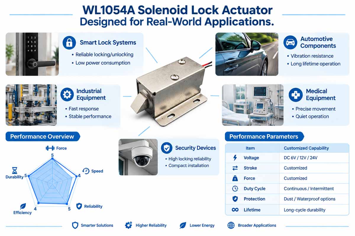
Solenoid lock actuators are used in industrial, commercial, and domestic applications where locks or access control functions can be activated via electrical signal.

Industrial equipment: Manufacturers use actuators in machine access panels, equipment enclosures, automated production systems, and service compartments. They unlock a latch or move a locking pin if the control system gives permission. All locking and interlock arrangements of dangerous machinery shall be designed for safety purposes.

Control Enclosures & Electronic Cabinets Solenoid actuators can be used to activate cabinet latches, covers of electrical equipment, and compartments with restricted access. The compact dimensions and customizable mounting structure are useful while installing into the cabinet with limited internal space.

Smart home and electronic locks: Depending on the locking architecture, the actuator unlocks a bolt or latch if the control system provides the command. For battery-powered products, the power consumption and thermal management should be optimized.

In vending machines and commercial equipment such as dispensers, payment terminals, storage compartments, and self-service units, solenoid actuators can be used to unlock or lock mechanical parts.

Automotive and transportation equipment. Among other applications are storage compartments, access panels, and some other electrically controlled mechanical parts.

Medical and specialized equipment: Solenoid lock actuators can perform controlled movement of access covers and internal mechanisms.

Before choosing an actuator, engineers should consider such factors as force, stroke, duty cycle, operating temperature, vibrations, contamination, power-loss behavior, and required service life.

Why Are Solenoid Lock Actuators Gaining Popularity in Smart Home Door Lock Systems?

The solenoid lock actuators are attractive for the smart home door lock system since they facilitate the control of the mechanical locking functions by electrical signals in small electronic products.

1. Integration with Electronic Access

The solenoid actuator can be integrated with keypads, access cards, biometric readers, mobile applications, and home automation controllers. The control system then authorizes an operation and energizes the actuator accordingly.

2. Compact mechanical design

The space inside many smart locks is limited for the motor, gearbox, battery, circuit board, and locking parts. A properly designed solenoid actuator can provide a direct linear motion with relatively few mechanical components.

3. Fast actuation

The solenoids are capable of producing rapid motion of the plunger, so they are suitable for unlocking latches and actuating small locking devices.

4. Flexibility in OEM customization

Manufacturers can also customize actuator dimensions, force, stroke, voltage, mounting features, cable length, and connectors according to the particular lock architecture.

5. Possibility of low-power operation

The typical solenoids consume power when they are energized. However, a latching solenoid can be designed so that it will hold the position without the coil being energized. This is helpful for the battery-operated devices, but the control electronics and other parts of the system still consume energy.

6. Flexible integration of products

The solenoid actuators can be designed for various mechanical architectures and used for electronic cabinets, storage locks, parcel boxes, and some residential access products.

7. Design considerations

Smart door locks have to deal with battery life, mechanical security, emergency access, environmental protection, noise, and reliability. The operation of the solenoid actuator alone will not provide secure locking and compliance with door lock standards.

The OEM developers have to select the appropriate actuation mechanism and validate it within the framework of the entire lock assembly for successful integration.

Custom Solenoid Lock Actuator Advantage and Disadvantage

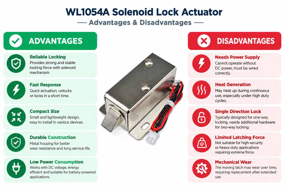
WL1054A Solenoid Lock Actuator Pros and Cons

ย Advantages of Solenoid Lock Actuators

Advantages of Solenoid Lock Actuators Solenoid lock actuators bring multiple advantages to the electronically controlled locking systems, but they also have certain limitations.

Pros

Compact size: Many solenoid actuators can fit into small spaces, and they are suitable for electronic cabinets, smart locks, access panels, and small equipment.

Fast electromagnetic response: They can produce fast linear motion if correctly specified and energized.

Simple electrical control: Many designs can be controlled by a suitable switching circuit, microcontroller, relay, or access-control system.

Flexibility in customization: OEMs can customize dimensions, voltage, stroke, force, mounting structures, and electrical connections for the host product.

Repeatable operation: Properly designed and tested actuators can produce repeatable motion over many operations.

Disadvantages of Solenoid Lock Actuator

High power consumption: The conventional solenoids may require high current to operate. The continuous energizing produces high heat.

Reduced force at long stroke: The available force becomes lower the farther away from the optimal magnetic position the plunger is pulled.

Mechanical wear: Springs, plungers, guides, latches, and other mechanical components will wear over time.

Noise and impact: The plunger movement may produce audible click or mechanical impact.

Environmental sensitivity: Dust, moisture, corrosion, misalignment, and temperature can affect reliability.

Power-off implications: The locked state is defined by the actuator and the mechanical design.

Conclusion: The solenoid lock actuators are well suited for the compact electrically controlled mechanisms provided that the force, stroke, thermal, mechanical integration, and power-off behavior are designed properly.

Troubleshooting of Solenoid Lock Actuators

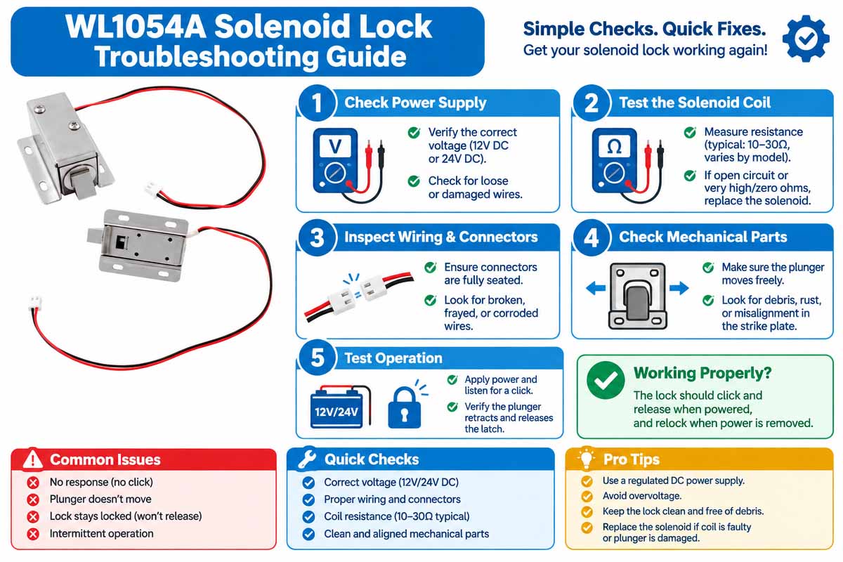
WL1054A Custom Solenoid Lock Troubleshooting Guide

The problems with solenoid lock actuators can be caused by electrical failures, mechanical obstruction, overheating, or improper system integration. The systematic approach allows identifying the problem.

1. The actuator does not operate

Possible causes: no supply voltage, wrong wiring, open coil, bad driver, plunger is mechanically stuck.

Actions: Check the control signal. Measure voltage at actuator terminals when energized. Check wiring. Check coil continuity in accordance with the manufacturer’s specifications. Disconnect power before checking for mechanical problems.

2. The actuator is moving, but it cannot unlock the lock.

Possible causes: Insufficient force, excessive friction, wrong stroke, misalignment, or excess latch preload.

Actions: Check actual load and stroke against the force vs stroke specification. Check for interference with the locking mechanism. Check mounting misalignment.

3. Too Hot for Coil

Possible causes: wrong voltage, wrong duty cycle, too long activation time, insufficient cooling.

Action: Measure voltage and current. Compare the operating conditions to the rated duty cycle. Check the control sequence.

4. Operation is not continuous.

Possible causes include loose connections, voltage drops, contamination, or mechanical binding.

Check connections. Measure the Supply with Load on. Check the plunger and guides for dirt or wear.

5. The Actuator Makes Some Noise

Possible causes: Over-impact, loose mount, misalignment, worn mechanical parts.

Actions: Check fasteners, mounting rigidity, design of end stops, and mechanical clearances.

SAFETY NOTE Disconnect electrical power before servicing. Never override the safety interlock to force the unit on. Replace any defective parts and check the entire locking system before returning the equipment to service.


FAQs about Custom Solenoid Lock Actuator

1. How to Select a Solenoid Lock Actuator -

The selection of the solenoid lock actuator depends on the force required, stroke length, operation voltage, current consumption, duty cycle, installation dimensions, and the environment where it is supposed to operate. You also have to understand if the actuator has to perform the push, pull, spring return, or latching function. For the industrial access safety applications, you have to specify the locking state required in the case of power failure and whether the position monitoring or emergency release is required. If you provide the drawing, application details, and performance requirements, your supplier will be able to ensure the proposed actuator meets your mechanical and electrical specifications.

2. Can I customize the Solenoid Lock Actuators for my OEM project?

Yes. The solenoid lock actuators are often customized to the specific needs of OEMs. Depending on the application, overall dimensions, mounting holes, plunger diameter, stroke length, actuation force, operating voltage, coil resistance, cable length, connectors, and housing materials can be customized. Manufacturers can also optimize the magnetic circuit and mechanical structure to improve performance in the installation space. Please let us know in advance what kind of 2D drawing, 3D model, or technical description you wish to share before requesting the quotation. This will enable your supplier to evaluate feasibility, the need for prototype development, tooling cost, lead time, and anticipated volumes.

3. How do I Calculate the Required Force and Stroke?

The required force and stroke are determined based on the locking mechanism and the mechanical loads on the actuator. First establish the stroke that is needed to operate the lock mechanism (e.g., bolt movement). Then calculate the required force considering the spring force, frictional forces, loads from any linkages, etc. As a rule, solenoid force depends on plunger position. Ask the manufacturer to provide the force vs. stroke chart. Check if the actuator will provide enough force in the actual operating stroke and at minimal operating voltage. Prototyping is always recommended before going into full production.

4. Can Solenoid Lock Actuator Run Continuously?

Continuity of operation depends on coil design, operating voltage, thermal characteristics, and the intended duty cycle of the actuator. Some solenoids are made for continuously operating, and others for intermittent use. Too many activations can cause overheating, insulation breakdowns, and shortened life. While comparing products, note its duty cycle capability, maximum ambient temperature, current consumption, and allowable coil temperature increase. If the application requires the lock to remain in place without continuous energy supply, choose the right latching solenoid or mechanical arrangement. Always check its performance at the actual operating conditions.

5. So, What's the Difference Between a Latching Solenoid and a Standard Solenoid Lock Actuator?

The spring-return actuator is normally powered on to move and automatically reverts to its default position upon de-energizing. The default position may depend on the mechanics and be either locked or unlocked. The latching solenoid is made with a magnetic and/or mechanical mechanism to maintain its position after the initial electrical pulse. In most cases, it does not require a continuous holding current, which saves energy on smart locks and access control systems using battery operation. But it may require an additional pulse or polarity change for changing states. Whichever one is better depends on the power availability, locking behavior, and control circuitry.

6. What is the Average Life Span of a Solenoid Lock Actuator?

The operational life span is determined by the design of the actuator, frequency of use, mechanical load, duty cycle, working environment, and quality of production. An apparatus that has been tested for a certain number of cycles in the laboratory conditions may act differently in a device that experiences more loads, temperature fluctuations, dust, and vibrations. While looking at different suppliers, ask them to specify the results of cycling tests, test conditions, and predefined failure modes. Do you need the lifespan to be specified for the solenoid only or for the locking system altogether? Testing of the prototype under the actual operating conditions can help you estimate realistic maintenance and replacement intervals.

7. Are Solenoid Lock Actuators Suitable for Industrial Safety Access Applications?

A solenoid lock actuator is used to actuate locking pins, latches, and release mechanisms in industrial equipment, cabinets, and access panels. But the actuator does not necessarily ensure that the system is safety-rated. Hazardous machinery may require certified interlocks, guard locking mechanisms, position monitoring, emergency release, and safety-related control circuits. Prior to component selection, engineers should conduct risk assessment and identify applicable machinery safety standards. Tell your supplier about the required operating environment, mechanical loads, power-off condition, and certification standards. The entire locking system has to be tested for safety.

8. What Information Should I Provide Before Asking Solenoid Lock Actuator Quote?

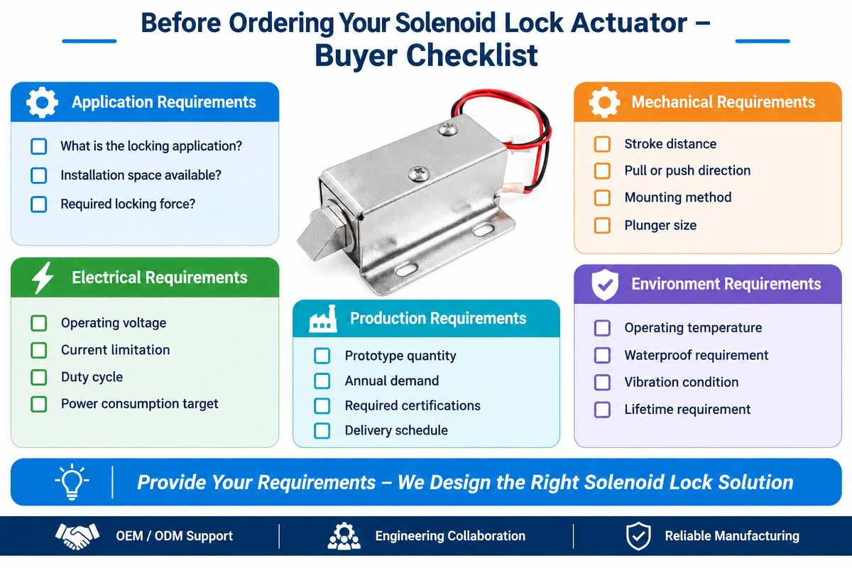
In order to receive a more precise quote, it would be great if you were able to provide as much of the following information as possible:

Application: Smart door lock, industrial cabinet, access panel, etc.

Dimensions: Available space for mounting.

Force: Required operating force at the particular stroke.

Stroke: Required actuator stroke.

Electrical specifications: Voltage, current limits, and controlling method.

Duty cycle: Time the actuator works and frequency of its use.

Environment: Ambient temperature, humidity, dust, wetness, and vibrations.

Lifetime: Required operating cycles and service life span.

Quantity: Quantity of prototypes, estimated annual demand, and anticipated production volumes.

Technical data: drawings, 3D model, test requirements, and applicable certificates.


How to Choose a Solenoid Lock Actuator

The secret to selecting the proper solenoid lock actuator is to match the electrical and mechanical performance of the actuator to your locking application. OEM engineers will take into account the following criteria while designing.

1. Define the locking function

Define what the actuator lock isโ€”a latch, pull back a bolt, release a pin, or actuate any other locking mechanism. You should clearly understand whether you need a push, pull, or latching actuator.

2. Calculate the required force

You should define the load that should be overcome (spring, friction, linkage resistance, and external mechanical load).

In locks it is important to distinguish the force to actuate the locking mechanism and the force to resist the forceful opening of the lock.

You should get the data on the force versus stroke from the manufacturer.

3. Define the stroke

You should measure the stroke of the plunger to define what distance it should cover to perform the required job. You should make sure that the stroke is sufficient but not too big to make the mechanical interference and produce an impact.

4. Define the voltage

Specify the nominal voltage, the acceptable variations of it, the available current, and the control algorithm. Ensure that the actuator will provide sufficient force to perform the required job at the actual conditions of the voltage supply.

5. Verify the duty cycle

Define how often your actuator will work and how much time will pass from turning ON to turning OFF. Continuous operation is quite different than switching ON and OFF frequently. The actuator should be able to produce the required performance without overheating.

6. Evaluate the power-loss behavior

Define whether your mechanism should lock or unlock if power fails. The spring return actuator, bistable latching actuator, and continuously energized actuator work differently. You should choose the actuator according to the operational and safety requirements of the locking system.

7. Consider the environment

Temperature, humidity, dust, water, vibration, corrosion, and orientation. Define the requirement for protection considering the environment.

8. Check the installation and lifetime

Check dimensions, mounting holes, connectors, cable run, and the available space. Estimate the realistic lifetime, taking into account the frequency of operation.

9. Ask to test the prototype

Test force, stroke, current, temperature rise, response time, noise, and lifetime in the intended assembly before series production.

Engineering practice. Provide the manufacturer with the drawing, operating voltage, force versus stroke, duty cycle, environment, and the estimated demand for the year. It will accelerate design and quotation.

Advice on Avoiding the Common Design Mistakes with Solenoid Lock Actuators

Incorrectly specified actuators may result in low force, overheating, poor locking behavior, excessive noise, and premature failure. The following mistakes are typically made early in the design process.

Mistake 1: Saying force without stroke

The solenoid can produce high force at one position of the stroke and lower force further along the stroke.

How to avoid it. Specify the minimum required force at the stroke position where it will be applied. Request the force vs. stroke diagram.

Error 2: Failure to recognize the limitations of the power supply

Voltage drops, cable resistance, driver limitations, and battery drain can all limit the current and thus magnetic force.

How to avoid it: test the actuator at minimum operating voltage and actual electrical load.

Mistake 3: Ignoring the duty cycle

The coils designed for an intermittent duty cycle can overheat if energized continuously.

How to prevent it: Set the activation time, repetition frequency, ambient temperature, and the temperature rise allowed.

Mistake 4: Failure to define the default state

The actuator may either return to its initial state when the power is off, keep the previous state, or require another electrical pulse.

How to avoid it: Specify what kind of a lock is desiredโ€”fail-safe, fail-secure, spring return, or bistable. Analyze the whole system and safety requirements.

Mistake 5: Trying to Use the Actuator to Prevent Forced Entry

The force of the actuator’s pulling may differ from the force required to break open the lock.

How to avoid it: Ensure that the mechanical locking elements are capable of withstanding the external load without the action of the actuator force.

Mistake 6: Failure to recognize the importance of mechanical tolerances

Misalignment, friction, contamination, and manufacturing tolerances can inhibit proper operation.

How to avoid it Definition of the alignment tolerances, guidance clearances, mounting tolerances, and appropriate wear-resistant materials.

Mistake 7: Not Validating Your Prototype

The device that works on the test bench may not work when installed in the whole assembly.

How to avoid it: Test prototypes in the actual equipment in the actual conditions of voltage, load, temperature, vibration, and frequency of operations.
 

Get A Free Quote Now

Contact Form

Related Products

Related News

Scroll to Top

Get A Free Quote Now !

Contact Form
If you have any questions, please do not hesitate to contact us.
Weilong Solenoid Company Culture