Chapter 1: Introduction on Inductor Coils?
The inductor coil, more commonly known as an ‘inductor’ or ‘choke,’ is a basic electronic component that stores energy in the form of a magnetic field when an electric current is passed through the coil. An inductor coil is simply a copper wire that is wound up into a coil. A core material such as ferrite or iron powder is often used. The main characteristic of the coil is its ‘inductance,’ represented by ‘L,’ measured in Henry (H), which is the measure of its opposition to changes in current.
An analogy that helps to understand the operation of an inductor is that of the mechanical concept of ‘inertia.’ Just as the mass of an object resists changes in its velocity, the ‘inductance’ of the coil resists changes in the current. An inductor is therefore an essential component of electronic circuits due to its applications:
Energy Storage: Storing energy temporarily using a ‘Switch-Mode Power Supply’ (SMPS).
Filtering: Filtering ripples from the mains supply.
Impedance Matching: Matching impedance between two circuits.
Signal Conditioning: Filtering out unwanted frequencies from the desired signal.
Chapter 2: Core Principle: How Does an Inductor Coil Work?
An inductor coil works with the help of two main laws of electromagnetism:
Ampere’s Law: An electric current passed through a wire produces a magnetic field. The more the wire is wound up into a coil, the greater the magnetic field is concentrated inside the coil.
Faraday’s Law of Electromagnetic Induction: A changing magnetic field inside the coil produces a voltage. However, Lenz’s Law asserts that the voltage is always equal to the opposition of the current change.
This opposition to change is known as inductive reactance (X_L), and the formula to compute this is
X_L = 2πfL
Where f is the frequency.
This formula points to the most important characteristic of an inductor:
When f = 0 (i.e., DC), then X_L = 0. The ideal inductor is a short circuit to DC.
When f > 0 (i.e., AC), then X_L > 0. The inductor resists the AC.
This dependence on frequency is the basis of all applications involving an inductor.
Chapter 3: Types of Inductor Coils Weilong Focusing on : A Detailed Breakdown
The choice of the right type of inductor is essential. The core type and the way the core is constructed define the performance envelope.
3.1 Air Core Inductor
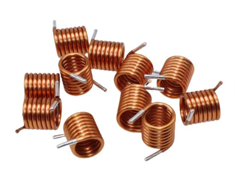
How it is constructed: A coil of insulated wire around a hollow, non-magnetic core (ceramic, plastic), which could be self-supporting. The core is air.
Its technical characteristics:
High Q Factor: The air core has zero core loss.
No Saturation: The air core does not saturate even at high current densities.
Low Inductance Density: The air core has the lowest inductance density.
Not Shielded: The air core is not shielded from the outside world.
Its primary applications:
High-frequency RF applications above 50 MHz.
Matching networks.
Resonant tank circuit in transmitters.
3.2 Bobbin Coil/Choke
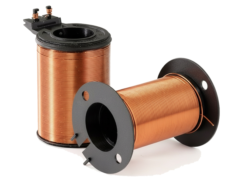
How it is constructed: Insulated wire on a cylindrical plastic former.
Its technical characteristics:
Very Low Cost: The most cost-effective solution.
Easy Automation: Simple geometry allows for fast machine-based winding.
High Flux Leakage: The open structure allows for considerable radiated electromagnetic interference (EMI).
Limited Inductance Range: Typically used for values ranging from microhenries (µH) to a few millihenries (mH).
Primary Applications: Simple AC line chokes, input filters for power supplies, ballasts for fluorescent lights, and simple noise suppression where EMI standards are not stringent. Ferrite Core Inductor
Construction: A wire-wound inductor with a ferrite core made of a ceramic mixture of iron oxide with manganese-zinc (MnZn) or nickel-zinc (NiZn). Ferrite core inductors come in E, I, RM, and pot core shapes.
Technical Characteristics:
High Permeability: Offers very high inductance in a small package.
Frequency-Dependent Material: Ferrite materials with MnZn composition are suitable for kHz to low MHz (power supply applications), while those with NiZn composition are suitable for high MHz (RF applications).
Core Saturation: Saturates when the magnetic flux density exceeds a certain level (Saturation Current, I_sat). This results in a catastrophic failure of the inductor.
Temperature Sensitivity: May vary with temperature.
Primary Applications: The workhorse of Switch Mode Power Supply (SMPS) design (as transformers and output chokes), broadband transformers, EMI/RFI suppression chokes, and DC-DC converter inductors.
3.3 Toroidal Core Inductor
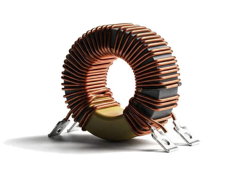
Construction: A wire-wound inductor with a doughnut-shaped ferrite, powdered iron, or amorphous metal core.
Technical Characteristics:
Closed Magnetic Path: The ring shape encloses almost all magnetic flux inside the core. The benefits include:
Very Low EMI Radiation & Susceptibility.
High inductance and high efficiency for a given core volume.
Minimum flux leakage to avoid interference with neighboring components.
More Complex Winding: The manual winding process is expensive.
Primary Applications: High-end power supplies, audio crossovers, differential mode chokes, and applications where low EMI is a requirement.
3.4 Ferrite Core Inductor
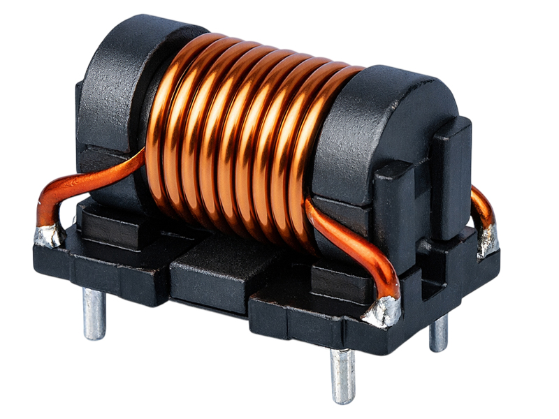
Construction:
A wire-wound inductor constructed using a ferrite core, usually of the rod, E-core, drum, or bobbin type, for efficient magnetic flux guiding and concentration.
Technical Characteristics:
High Magnetic Permeability:
Ferrite material has strong magnetic concentration and stable inductance. The major advantages:
High inductance in a compact size.
Low core loss at medium to high frequencies.
Good EMI suppression performance when properly shielded or designed.
Has a lightweight structure that makes it suitable for high-frequency switching circuits. Flexible Winding Structure: In comparison, automating the winding of ferrite cores is simpler compared to closed toroidal cores. Consequently, ferrite cores are less costly. Primary Applications: Switching power supplies, DC to DC converters, EMI filters, transformers, power inductors for automation equipment, devices used for communication, and general electronic circuits.
3.5 Wireless Charging Coil
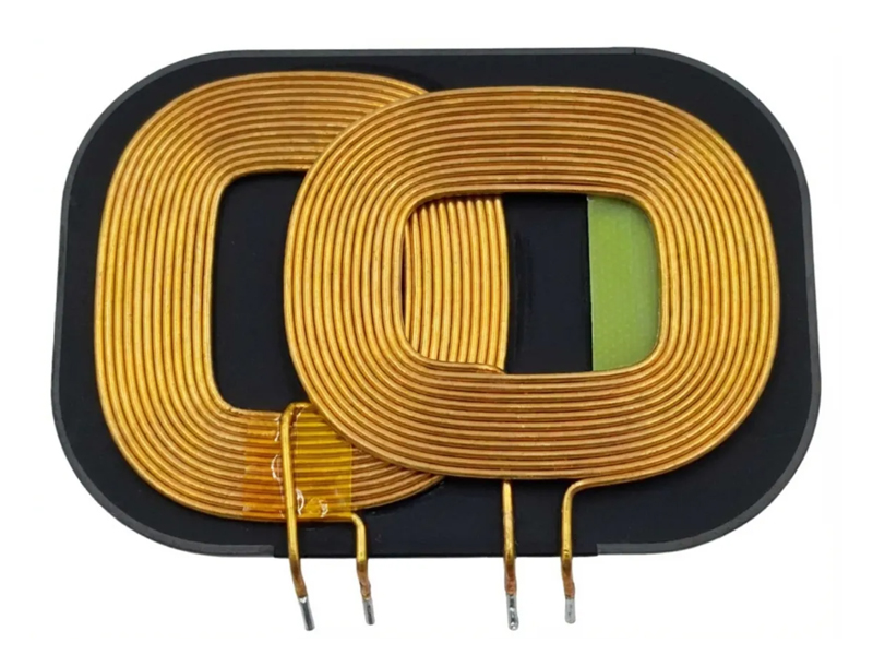
Construction: A flat, spiral planar inductor, which can be single-layered or multi-layered. Litz wire is often used to minimize AC resistance at a specific operating frequency. A ferrite sheet or array is placed at the bottom to shield and focus the magnetic field towards the receiver coil.
Technical Characteristics:
Optimized Loose Coupling: The coil operates efficiently when placed at an air gap with a specific coil.
Tuned to a Standard Frequency: Typically operates at 110 to 205 kHz (Qi standard) and 6.78 MHz (A4WP standard).
Efficiency is paramount: The design aims to achieve maximum efficiency by minimizing AC resistance (hence Litz wire).
Primary Applications: Wireless charging coils for smart
phones, wearable gadgets, toothbrush chargers, and resonant charging systems for medical implants and electric vehicles.
Chapter 4: Technical and Application Comparison
| Type | Core Material | Typical Inductance Range | Frequency Suitability | Key Advantage | Main Limitation | Best For |
| Air Core | Air/Non-Magnetic | nH to µH | Very High (MHz-GHz) | High Q, No Saturation | Low Inductance/Density | RF Circuits, Tuning |
| Bobbin Coil | Air or Simple Former | µH to mH | Low-Mid (Hz-kHz) | Low Cost, Simple | High EMI Radiation | Basic Chokes, Ballasts |
| Ferrite Core | Mn-Zn, Ni-Zn Ferrite | µH to H | Wide (kHz-MHz) | Good Balance of Size/Cost | Thermal & Saturation Limits | SMPS, Broadband Apps |
| Toroidal | Ferrite, Powdered Iron | µH to H | Audio to MHz | Low EMI, High Efficiency | Higher Cost/Winding | Precision Audio, Medical, Low-EMI PSU |
| Wireless Charging | Ferrite Sheet/Plate | µH Range | Specific Bands (kHz-MHz) | Optimized Coupling | Distance/Alignment Sensitive | Contactless Power Transfer |
Chapter 5: Critical Design Considerations for Inductor Selection
The selection of the proper inductor requires consideration of these critical parameters and their comparison with the requirements of your circuit:
Inductance Value (L): The nominal value needed for proper operation of the circuit.
Current Rating (The Two Critical Limits):
Saturation Current (I_sat): The DC current at which the core will saturate, usually defined as the current at which the inductance will drop by 10-30%. Exceeding this value will result in catastrophic failure of the inductor.
Thermal/RMS Current (I_rms): The DC current at which the winding will heat up to a predetermined maximum due to DC Resistance (DCR) loss.
DC Resistance (DCR): The inherent resistance of the wire used for the coil windings. Causes I²R power loss, which affects efficiency and results in self-heating.
Frequency of Operation: The core material should be selected based on low core loss at the desired operating frequency, especially when using ferrite materials, which are designed for operation at kHz and MHz frequencies.
Quality Factor (Q): Q = X_L / ESR. High-Q indicates a ‘pure’ inductor with low loss, which is critical for resonant circuits and filters with high selectivity requirements.
Shielding:
Unshielded: Open magnetic field, usually used for bobbin coils.
Semi-Shielded: Magnetic material covering part of the coil windings.
Fully Shielded: Closed magnetic path, usually used for toroids with magnetic epoxy core material.
Physical Constraints:
Footprint: 1210, 1812, etc., used to identify SMD footprint packages.
Height: Height of the part, especially important when considering through-hole vs. SMD mounting options.
Temperature Stability: The temperature coefficient, which indicates how much the inductance will drift over the desired operating range, such as -40°C to +125°C.
Tolerance: Standard tolerance is ±10% or ±20%. Tolerances as tight as ±5% can be achieved at higher costs.
________________________________________
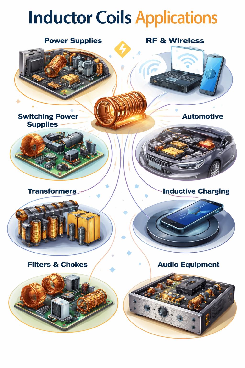
Chapter 6: Inductor Coil Application List by the Type
Power Conversion & SMPS:
Input Filter: Bobbin or Toroidal Choke Inductor
Power Stage (Buck/Boost): Ferrite Drum Core or Shielded SMD
Output Filter: Ferrite Core or High-Current Toroidal
RF & Wireless Communication:
Impedance Matching: High-Q Core Air Core or Ceramic Core SMD
Filters & Baluns: Air Core, Toroidal (HF, VHF)
Antenna Loop: Large Air Core or Ferrite Rod
Noise Suppression (EMI/EMC):
Board Level: Ferrite Chip Beads
Power Line: Toroidal Common Mode Chokes
Cable: Snap-on Ferrite Cores
Audio Equipment:
Crossover Network: High Q, Large Gauge Toroidal
Tube Amp Output: Gapped Ferrite or Laminated Iron Core
Wireless Power Transfer: Dedicated Planar Wireless Charging Coils with Ferrite Shielding
Lighting:
Bobbin Coils in LED Driver Inductors
Traditional Magnetic Ballast
Automotive Electronics:
AEC-Q200 qualified ferrite core inductors, toroidal inductors
ECUs, Infotainment, ADAS
Medical & Industrial:
High Reliability Toroidal Inductors
Isolation, Safety, Low Leakage
Chapter 7: Buyer’s & Designer’s Checklist For Inductor Coil
Critical Specs:
Required Inductance (L) and Tolerance
Current Analysis:
Is the peak current requirement in the design less than I_sat?
Is the RMS current requirement in the design less than I_rms?
Frequency Check:
Is the frequency requirement within the inductor’s optimized frequency range?
Loss Budget:
Is the DCR of the inductor low enough?
Performance:
What is the Q requirement at the operating frequency?
EMC/Shielding:
Is a shielded inductor (e.g., toroidal, molded) necessary to pass EMI tests?
Mechanical:
Are the inductor coil’s footprint, height, and mounting style compatible with the PCB design?
Environmental: Operating temperature range and required reliability standards (e.g., AEC-Q200).
Regulatory Compliance: Any required safety or industry-specific certifications.
Cost & Availability: Meets budget and has a reliable supply chain for production volumes.
Chapter 8: Frequently Asked Questions On Inductor Coils
Q: What’s the difference between an inductor coil and a choke coil?
A: Functionally, an inductor coil and a choke are the same device. A choke refers specifically to an inductor used to “choke” or block high-frequency AC signals but allow DC or low-frequency AC.
Q: Can I replace the inductor coils with a higher current rating?
A: Yes, it is generally safe but highly recommended for maximum reliability. It will be larger and more expensive.
Q: Why does inductor saturation matter in a switch-mode power supply?
A: If the inductor in a Switch Mode Power Supply (SMPS) becomes saturated, the inductance drops almost to zero. This results in the switching transistor seeing an extremely high current spike as the inductor “collapses.” This excessive current spike will cause the transistor to overheat, leading to a potential catastrophic failure of the transistor and the inductor.
Q: When should I use Litz wire?
A: When designing inductors for operation at high frequencies (tens of kHz up to MHz), the skin effect becomes an issue. The use of Litz wire reduces AC resistance due to the increased surface area available for the current flow.
Q: What are the physical considerations when orienting inductor coils on a printed circuit board to minimize noise?
A: Unshielded inductors should be located at a distance from sensitive analog traces or integrated circuit devices. The magnetic field of one inductor should be at a right angle to those of nearby inductors. A solid ground plane should be placed under inductors, but this plane should never be located at the center of power inductors, as this could cause eddy currents.
________________________________________
Chapter 9: Future Trends of Inductor Coils
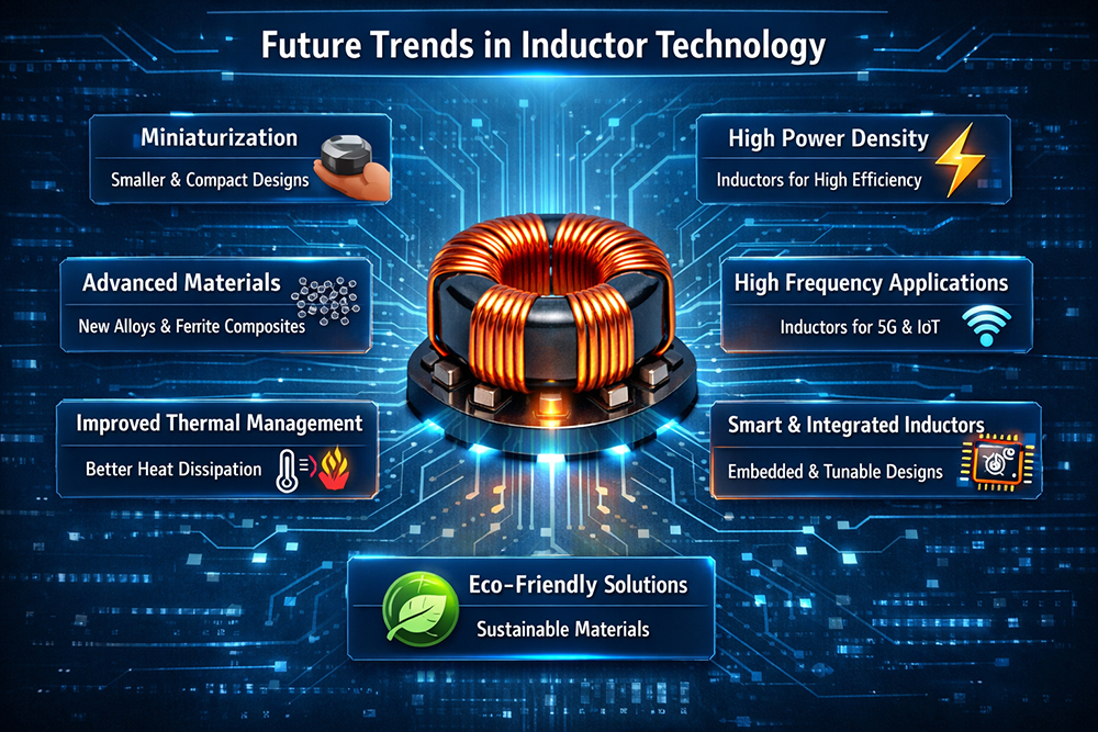
Future Trends in Inductor Technology:
Extreme Miniaturization: The quest for ever-smaller, high-current SMD inductors will continue with the aid of cutting-edge materials technology and 3D winding techniques for wearable electronics and other ultra-miniature gadgets.
High-Frequency Power Conversion: The move to wide-bandgap semiconductor devices such as GaN and SiC will cause power conversion frequencies to rise to the MHz range. The need will be for ultra-low-loss inductor materials with high-frequency capability and low parasitic capacitance.
Integrated Passive Devices (IPDs): The trend towards integrating inductors within printed circuit boards (embedded components) or within integrated circuit packages.
Advanced Magnetic Materials: The development of nanocrystalline and amorphous metallic materials offering superior saturation flux density, reduced core losses, and improved thermal characteristics compared to ferrite materials for high-power, high-efficiency power supplies.
Smart Inductor Coils: Research into voltage- or current-controlled inductors and inductors with built-in sensors for condition monitoring.
Chapter 10 : Conclusion Of Inductor Coils
Mastering the selection of the inductor coils is the key skill for the electronic designer. From the simple filtering of noise in a power adapter to the more sophisticated resonant coupling of a wireless EV charger, the humble coils of the inductor are ubiquitous. With the rigorous application of the concepts introduced within these pages, the reader is encouraged to optimize the selection of the inductor. It is always important to consult the latest data sheet information from the manufacturers, as material science is continually advancing to accommodate the needs of the next generation of electronic devices.