Push-Pull C Frame Solenoid for Medical Equipment solutions
Push-Pull C Frame Solenoid for Smart Lock System solutions
Push-Pull C Frame Solenoid for Vending Machine automation solutions
Push-Pull C Frame Solenoid for Packaging Equipment solutions
Push-Pull C Frame Solenoid for Sorting Equipment solutions
Push-Pull C Frame Solenoid for Textile Machinery solutions
Push-Pull C Frame Solenoid for Medical Equipment solutions
Push-Pull C Frame Solenoid for Smart Lock System solutions
Push-Pull C Frame Solenoid for Vending Machine automation solutions
Push-Pull C Frame Solenoid for Packaging Equipment solutions
Push-Pull C Frame Solenoid for Sorting Equipment solutions
Push-Pull C Frame Solenoid for Textile Machinery solutions

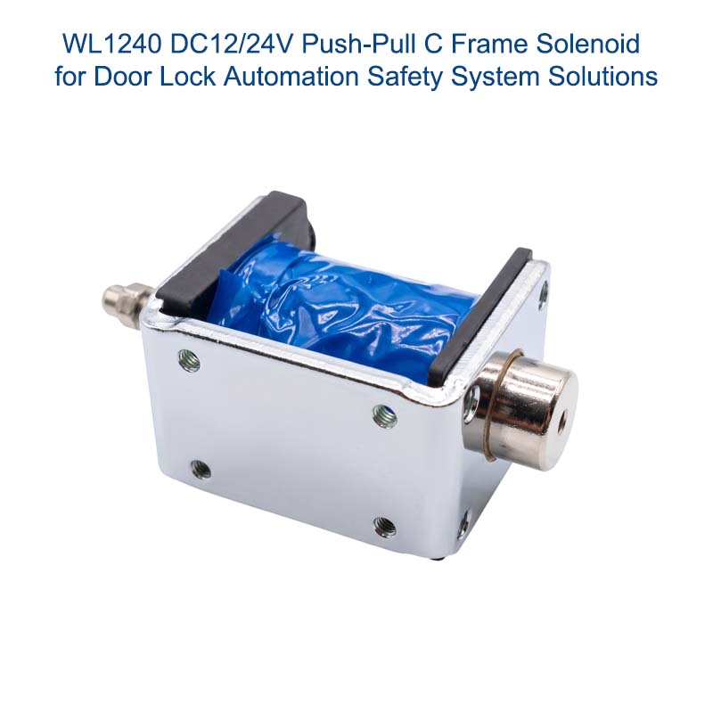
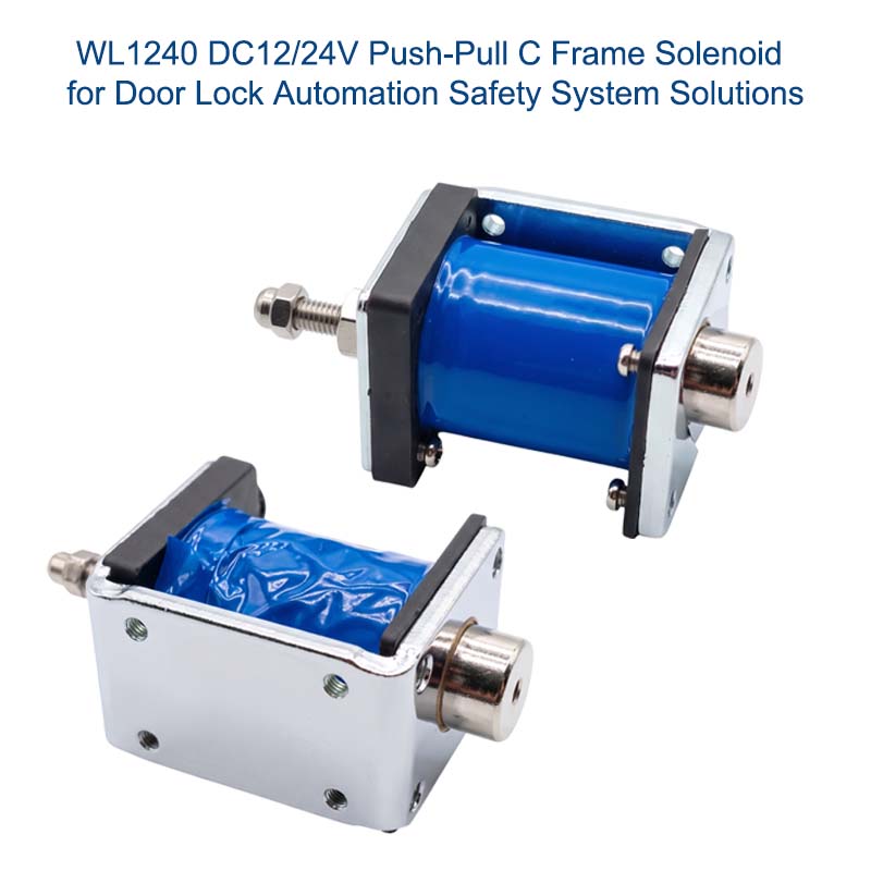
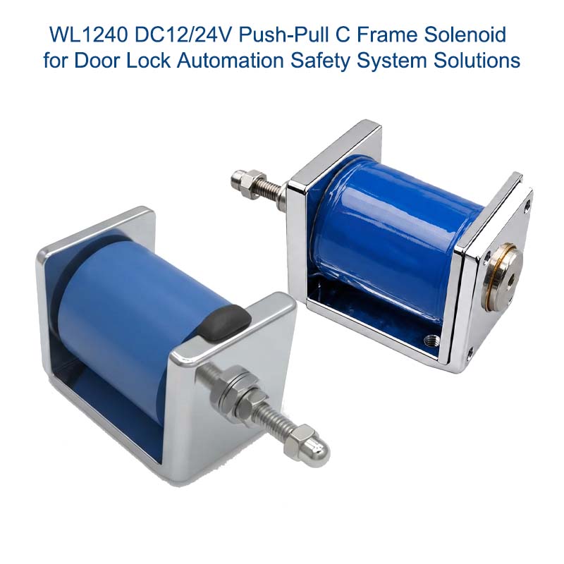
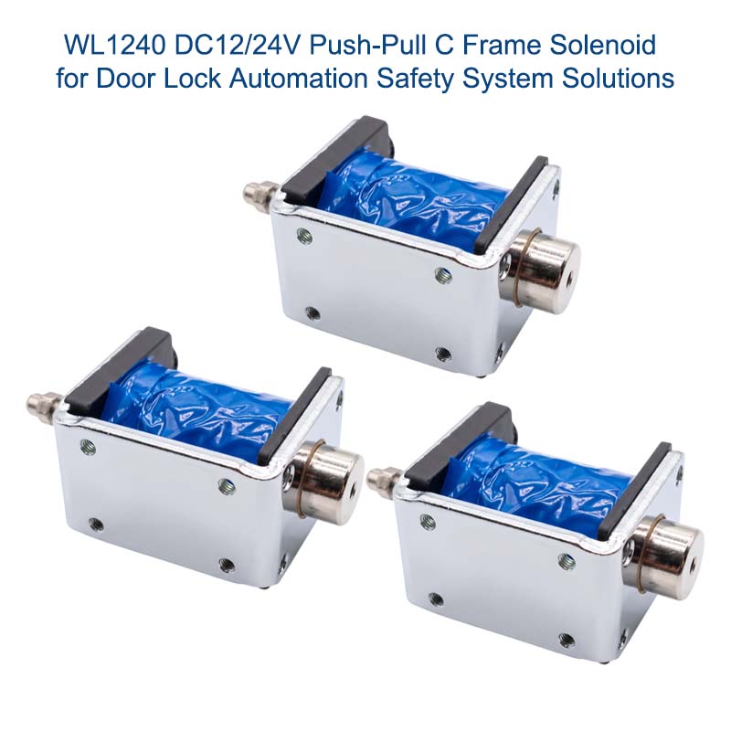
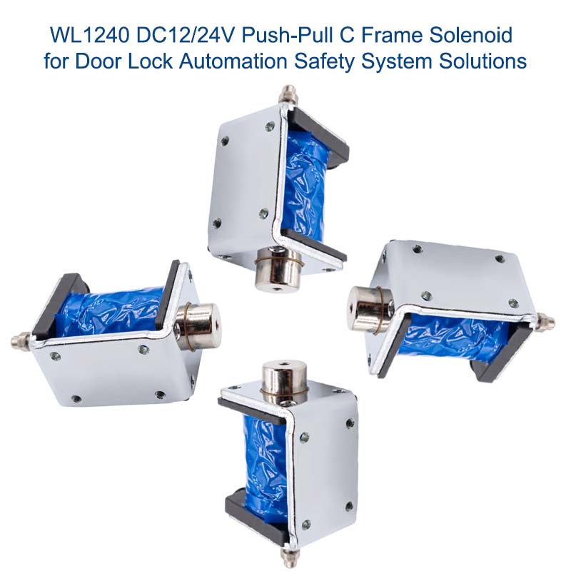
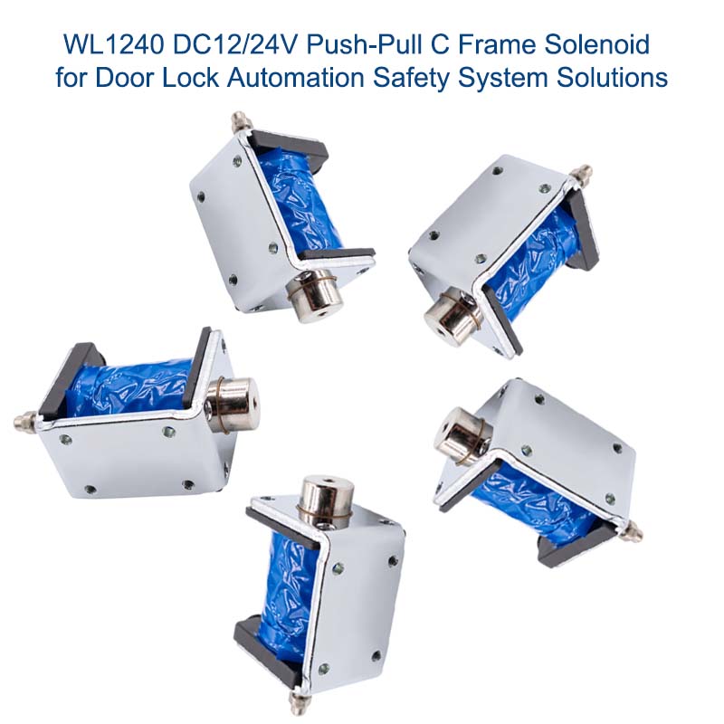
WL1240 Push-Pull C Frame Solenoid for Robotic Equipment Solutions

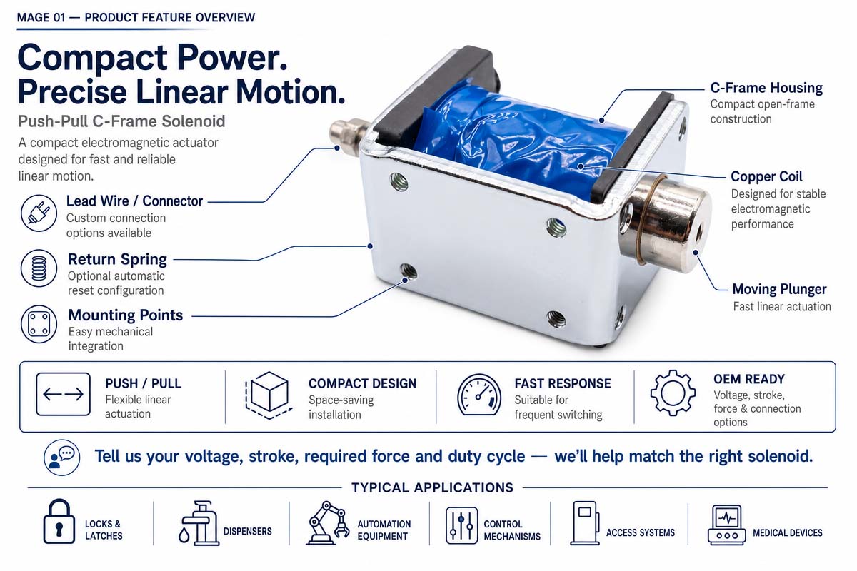
Push-Pull C Frame A solenoid is a compact electromagnetic linear actuator that provides fast and repeatable mechanical movement in industrial and commercial equipment. The design of the solenoid includes an open C-shaped metal frame enclosing the coil and a movable plunger.

When electrical energy is provided to the coil, the coil generates a magnetic field attracting the plunger. The movement can be converted to the push or pull output depending on the design of the shaft or mechanical linkage. The voltage, stroke, force, duty cycle, mounting, spring return, lead wires, connectors, and plunger design of the solenoid designs vary.

Typical applications are electronic locks, vending machines, medical and laboratory equipment, packaging and sorting machines, office machines, access control devices, and automated systems.

Correct selection of the solenoid is based on the proper match of the required force at the stroke, the voltage, energization time, cycle rate, temperature, available space, noise, and lifetime. Thermal and mechanical design increases reliability and repeatability of the operation during the lifetime of the product.

Push-Pull C Frame Solenoid Product Overview

A push-pull C frame solenoid is a compact linear actuator that consists of the wound electromagnetic coil, ferromagnetic frame, movable plunger, shaft, and optionally a return spring. Typical product configurations are defined by the rated voltage, stroke, force curve, power, duty cycle, coil resistance, mounting dimensions, plunger design, return mechanism, and electrical termination.

The standard solenoids are used in general switching and latching applications, while the custom solenoids can be designed for special brackets, connectors, shafts, springs, noise requirements, or operating conditions. Since the force is highly dependent on the plunger position and coil temperature, the product evaluation should be performed with real load, actual stroke, drive waveform, ambient temperature and intended cycle profile prior to production.

How does push-pull C frame solenoid work?

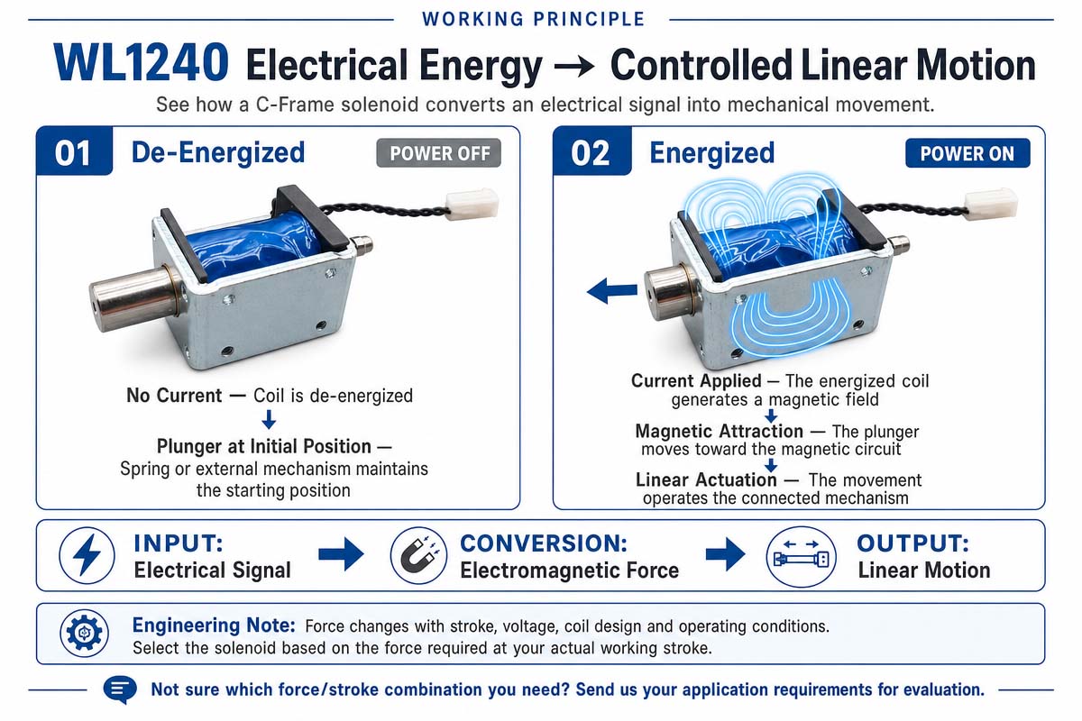
A push-pull C frame solenoid is a device that converts electrical energy into short-stroke linear mechanical motion. When DC power is applied to the coil, the current flow through the coil winding creates a magnetic field. The C-shaped frame forms a part of the magnetic circuit, and the ferromagnetic plunger is attracted to the low-reluctance area of the magnetic circuit.

The mechanical force is created as the plunger is moved into the coil. In the pull configuration the plunger working end is drawn backward, pulling the attached load. In the push configuration the inward movement of the plunger is converted into an outward pushing action using the shaft coming from the other side of the plunger.

In the normal operation of the solenoid, when the electrical energy is turned off, the plunger is returned to the initial position by the return spring or by gravity or by some external force.

The force of the solenoid is normally dependent on the stroke length. The air gap is normally large in the beginning, and the force increases when the plunger approaches the energized position. The actual force is dependent on the coil temperature, voltage, spring load, friction, alignment, and the duty cycle.

The coil is inductive in nature, and therefore the control circuitry should include adequate switching and transient protection. Depending on the release rate and electronics requirements, flyback diodes, TVS devices, snubbers, or any other suppression devices can be employed.

Key Characteristics of a Push-Pull C Frame Solenoid

Key characteristics of the Push-Pull C Frame Solenoid include a compact open-frame design, fast linear actuation, simple control, and flexible mechanical integration. The C-frame design allows saving size, material, and cost compared to the enclosed actuators. Designers can select various voltages, stroke lengths, forces, plunger shapes, mounting holes, springs, leads, and connectors.

Depending on the shaft arrangement, the solenoid can be arranged to provide either pull or push functions. Additional useful characteristics include fast response, repeatable switching, simple driver control, and compatibility with sensors and interlocks. The normal operation is highly dependent on the stroke, duty cycle, voltage, temperature, load alignment, and cooling.


Push-Pull C Frame Solenoid Product Video

Push-Pull C Frame Solenoid Product Detailed Display

Compact Push-Pull C Frame Solenoid Technical Data Sheet

Brand Weilong Technology Model Number WL1240
Rated Voltage (V) DC 6-48V Rated Power (W) 10–60 W
Work Model PUSH-PULL Type Holding Force (N) 1–10 N
Stroke (mm) 1–7 MM Reset Time(s) 1 S
Service Life 300 Thousand Times Certification CE, RoHS, ISO9001,
Material Carbon Steel Housing with Zinc-Plated Coating Lead Wire Length (mm) 200
Install Style Adjustable Screw Tolerance of Dimension ± 0.1 MM
Water-proof None Insulation Class F 155 Cel. Degree
Hi-Pot Test AC 600V 50/60Hz 2s Non-excitation Holding Force 0
Working Temperature -10°C-100°C Duty Cycle 1-100%
Thread Depth (mm) / Payment Term TT, or LC at Sight
Sample Order Yes. Warranty 1 Year
MOQ 500 pcs Supply Ability 5000 pcs per week
Delivery Time 30 Days Port of Loading Shenzhen

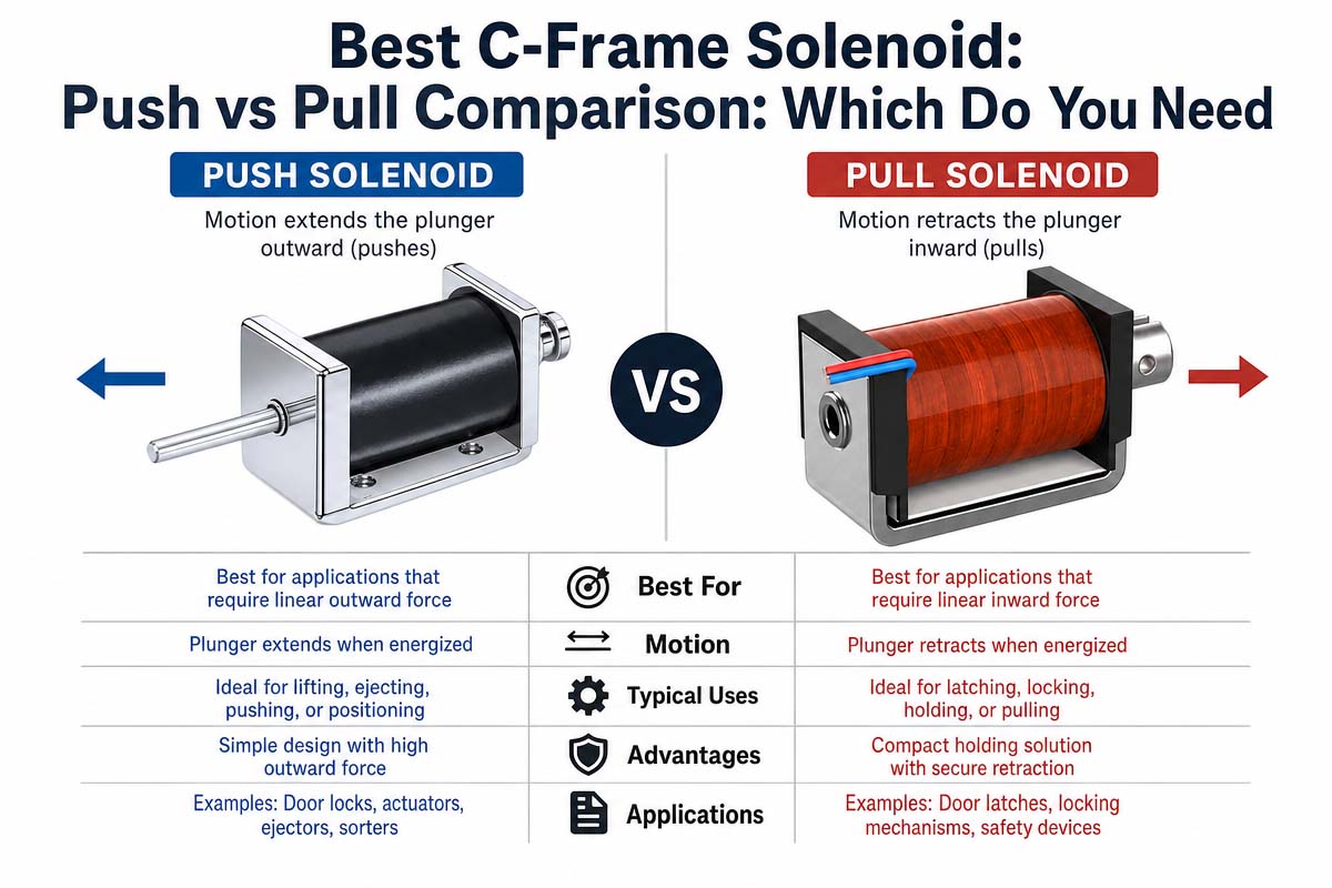
Best C-Frame Solenoid: Push vs. Pull Comparison—Which One Do You Need?

C Frame Solenoid Push VS Pull, which do you need

First of all, the fact should be clear that both push and pull C-frame solenoids operate using the same electromagnetic principles—when the current flows through the coil, the plunger is drawn toward the magnetic circuit. The terms “push” and “pull” relate to the transfer of the inward movement of the plunger to the external mechanism. It is the pull design, and the load is attached to the side that moves inward. In the push design, the shaft passes through or away from the solenoid, so the same inward movement of the plunger causes an outward push of the working end.

C Frame Pull Solenoid

A pull solenoid may be the preferable choice if it is possible to arrange the mechanism in such a way that the solenoid pulls the latch, releases the catch, pulls the lever, or pulls the gate toward itself. Direct pull operation simplifies the linkage and reduces the number of joints. It also helps to keep load in line with the axis of the plunger. Pull designs are often used in mechanisms of release, locks, selectors, and interlocks where the energization of the solenoid pulls the component back.

Push-Pull C Frame Solenoid

A push-pull C Frame solenoid is used if it is required to push out the pin, press the lever, trip the mechanism, eject the small part, move the gate away from the coil, or apply the force into some adjacent element. Push design solves the packaging problem, as the coil is situated behind some panel or mounting plate while the shaft acts on the opposite side. However, the proper guidance of the member to be pushed is required. The plunger of the solenoid should not be used as a structural guide for large side loads.

the Force and the structure

Neither push nor pull designs are inherently stronger. The force that can be generated depends on the magnetic design, power of the coil, air gap, stroke, temperature, duty cycle, geometry of the plunger, and opposing spring or friction loads. Force at the working stroke (compare at the start position). Mechanical stroke should also be taken into consideration (brackets, stops, linkage travel, and manufacturing tolerances).

Return behavior is another selection criterion. Some mechanisms generate their own return force, which may be gravity, a spring, or a driven assembly. The spring return design of the solenoid returns the plunger in the absence of the current. It should be ensured that the required safe state is reached after the loss of power. For safety-type devices, the entire assembly should be considered. It is impossible to assume that the solenoid is in a safe state.

Which one should I choose?

Both designs should be embedded in the real product. Which is the best? Take into consideration the space, load direction, shaft access, wiring, serviceability, impact noise, heat flow, contamination, and assembly sequence. Choose the configuration that transmits the force in the most direct way and creates the least side load and linkage.

Then prototype the design under minimum voltage, maximum load, hot coil, and full cycle rate. If both designs can be used, however, choose the one that has simpler mechanics, better alignment, easier manufacturing, and clearer fail-state behavior. “Best” The C-frame solenoid is thus not a push or a pull, but a design that has appropriate parameters and margin for the chosen application and can be verified in regard to reliability. Before releasing the product, it is necessary to check the supplier’s tolerances and sample production-intent lots.


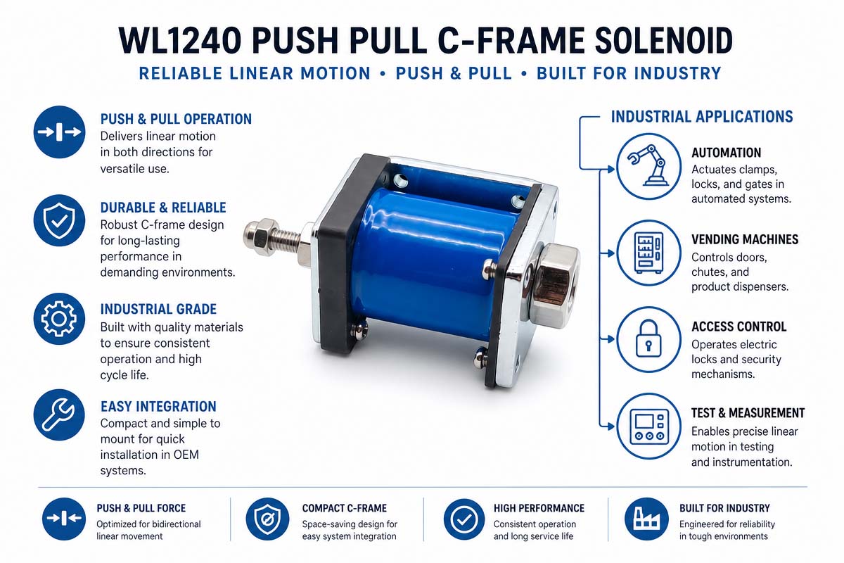
Custom Push-Pull C Frame Solenoid Industrial Application

Push-Pull C-Frame Solenoid Industrial Application

A push-pull C frame solenoid is used whenever a compact electrically controlled linear motion is required. They are used to control latches, stops, gates, selectors, ejectors, indexing mechanisms, and safety interlocks in industrial automation. They are used in packaging and sorting machines to divert products, release parts, activate cutters, or control small doors. Push-pull C frame solenoid control compartments and mechanisms in vending machines, kiosks, parcel lockers, tool dispensers, and access control systems.

In medical and laboratory equipment, correctly designed push-pull solenoids can activate covers, cartridge locks, reagent doors, clamps, shutters, release mechanisms, or other non-fluidic motion functions. Use in medical equipment requires specific validation of the product for temperature, noise, life, cleanliness, electrical safety, and regulatory requirements. The push-pull C frame solenoid controls paper paths, latches, feeders, and mechanical selectors in office machines and printers.

Additional applications include gaming machines, ticketing equipment, appliances, electronic cabinets, cash drawers, battery-swap stations, textile machinery, automated test fixtures, and small valve or damper mechanisms. A solenoid is especially useful in cases when simple on/off motion is required instead of precise servo positioning. Designers are required to validate the force over the whole stroke, the duty cycle, the return method, environmental exposure, and mechanical alignment before a solenoid can be used in production. This guarantees the actuator reliability in the actual conditions.

Why are push-pull C-frame solenoids so widely used in medical device automation?

The push-pull C-frame solenoid may be quite suitable for medical device automation, as many medical or laboratory mechanisms require simple and quick switching instead of precise positioning of the element. Small solenoid may be employed in order to release the latch, lock the cartridge, operate the shutter, move the mechanical gate, control the cover, connect the disposable part or trigger a small internal mechanism.

Compactness of the design is one of its advantages. The open design of the C-frame allows embedding of this solenoid in devices where there is no enough room for an enclosed actuator.

Fast response is another great feature of the solenoid. The electromagnetic actuator quickly switches the mechanism between two states, and this property is required for automatic sequences.

The push-pull C frame solenoid’s simple electronic control is a significant convenience. It may be triggered by the appropriate electronic driver and may be coupled with sensors, microcontrollers, and control logic. Engineering of special drive techniques such as peak and hold may help to optimize force, heat, power consumption, or response.

Customization of the solenoid is another feature that attracts designers to the C-frame solenoids. Parameters like voltage, stroke, force, shaft geometry, spring return, mounting details, connectors, lead wires and mechanical interface are flexible in relation to OEM design.

However, the presence of a standard C-frame solenoid in the medical equipment does not mean that it is a medical-grade solenoid. Medical device automation requires addressing the issues connected with electrical safety, temperature, noise, cleanliness, electromagnetic compatibility, reliability, materials, mechanical hazards, expected lifetime, and faults, along with appropriate regulations.

The push-pull C frame solenoid is the optimal solution for medical device automation if compactness, quick response, flexibility of the design, relative simplicity of the control and economical construction are required.


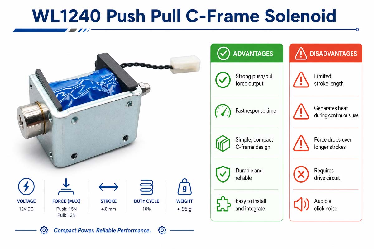
Push-Pull C Frame Solenoid Advantage and Disadvantage

Push-Pull C-Frame Solenoid Advantages and Disadvantages Explained

Push-Pull C Frame Solenoid Advantage

There are several practical advantages of the push-pull C frame solenoid. It is compact, mechanically simple and economical in the open frame construction for high-volume equipment. It provides fast linear travel on and off and can be easily controlled by a transistor, relay or by the appropriate driver circuit. The plunger can be directly integrated with latches, levers, gates and release mechanisms, minimizing the complexity of transmission. Many designs are also customizable for voltage, stroke, shaft shape, spring force, mounting, connector and lead length. If the solenoid is properly sized, the actuator can provide reliable repetitive motion with few moving parts.

Push-Pull C Frame Solenoid Disadvantage

The push-pull C frame solenoid disadvantage is primarily related to the force, heat and control limitations. The solenoid force is not constant in the stroke range. It normally increases as the plunger approaches the energized position. Duty cycle and thermal limitations should be observed because of significant coil heating that can occur as a result of continuous energization. The push-pull C frame solenoid provides less environmental protection compared to the sealed housing,, which is susceptible to dust, moisture, contamination, or corrosion. Impact noise and wear at the end of travel. Furthermore, the basic solenoid does not provide positioning capabilities without additional sensing and control. The designers in the final stage of the system development should take into account the voltage tolerance, return spring force, side loading, residual magnetism, driver protection and power consumption.

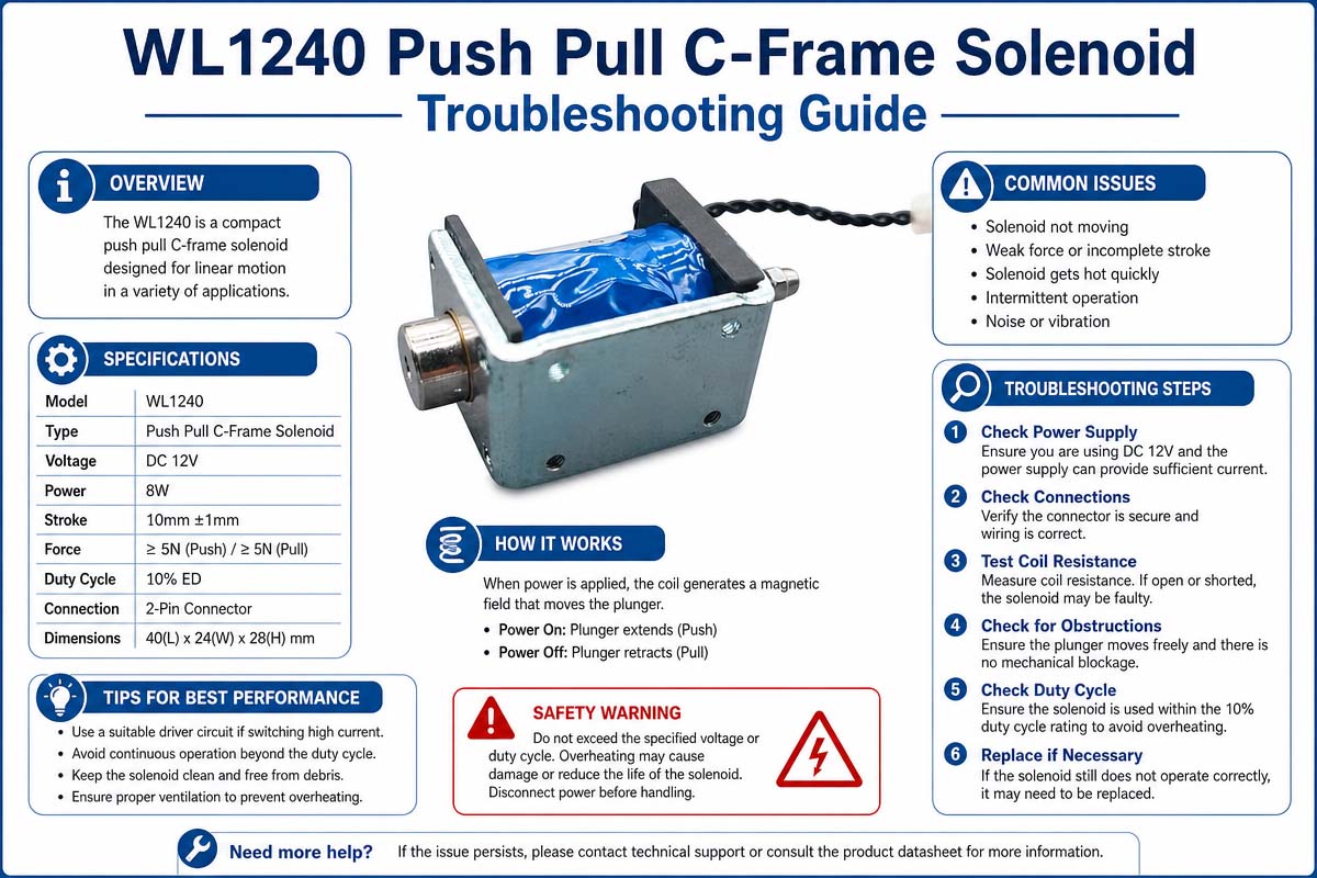
How to Troubleshoot a Push-Pull C Frame Solenoid

Push Pull C-Frame Solenoid Troubleshooting Guide I

When troubleshooting a push-pull C-frame solenoid, begin with the measurement of the supply voltage to the coil while the coil is energized. Check wiring, connectors, switches, driver transistors, fuses, and control signals. Measure the resistance of the coils. Compare with the specifications. An open circuit may indicate a broken winding. Low resistance may indicate winding damage or a wrong coil.

In case of low plunger strength, measure the stroke at the specified force. Check low voltage, high spring force, friction, side loading, contamination, misalignment, or any mechanical obstruction. Duty cycle, on-time, cycle frequency, temperature, ventilation, applied voltage, and drive strategy need to be examined if the coil gets overheated. “More force” does not mean “higher voltage,” even if you think it does.

For checking noisy operation, examine plunger impact, loose mounting, excessive clearance, hard stops, and return spring characteristics. To troubleshoot slow or irregular return, clean the moving surfaces as allowed, check the spring, and eliminate any binding. In case of magnetic stickiness even after the coil is de-energized, investigate residual magnetism, contamination, or mechanical preload. In case of repeated failure, perform a system-level investigation of the force margin, temperature rise, drive waveform, alignment, environment, and cycle-life requirements before continuously replacing parts without finding the root cause.


FAQs About Custom Push Pull C Frame Solenoid

1.How to choose the right push pull c frame solenoid?

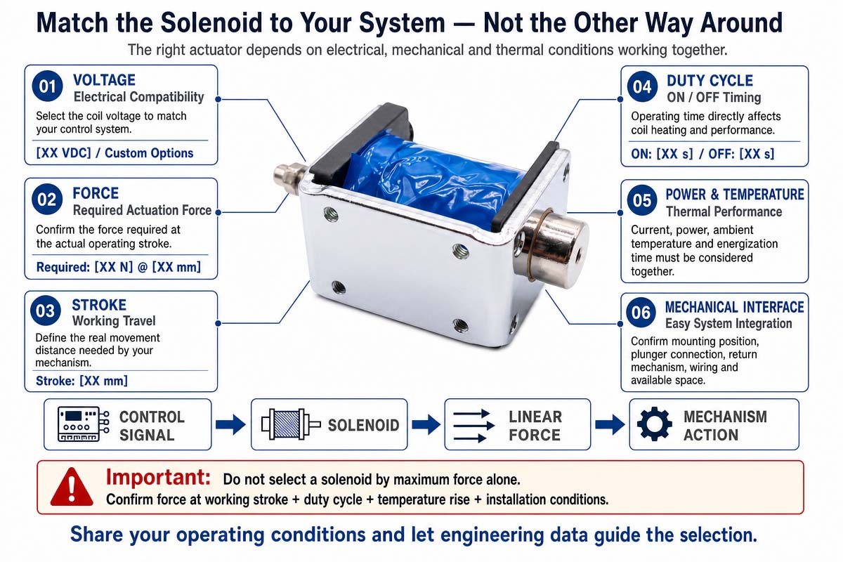
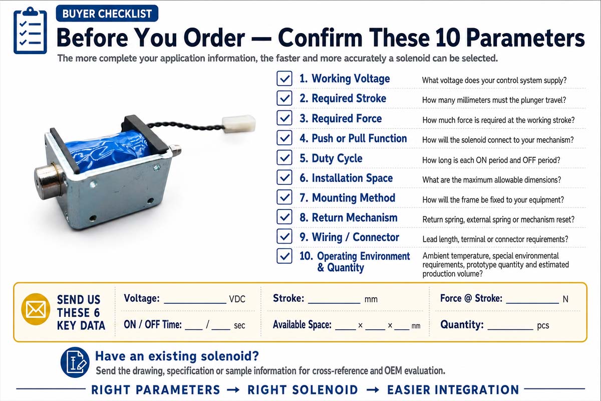
Firstly, start with the direction of pushing or pulling, stroke, force, voltage, duty cycle, frequency and installation space. As the solenoid force depends on the plunger position, take care of starting stroke force as well. Don’t forget about the return spring force, friction, ambient temperature, mount type, connectors, noise and the expected operation time. If you are an OEM customer, do not just buy a solenoid based on its dimensions or maximum force only. Provide your supplier with your actual load and operating conditions.

2. Push-Pull C Frame Solenoid - Push or Pull?

Choose according to your needs and the way of connecting it to your mechanism. A pull-type solenoid will work fine if there is a necessity of retracting a latch, lever, pin, or locking mechanism. The push type is perfect for extending the shaft and pressing, releasing, ejecting, or engaging components. Neither of these two configurations is necessarily better than the other. The best design is the one that will give you the most efficient force transfer, will reduce the side loads, provide a required fail state in case of losing electrical power and easy to install.

3. How much force should my C Frame Solenoid pull?

Do not choose the push-pull C frame solenoid according to its advertised maximum force. It is essential to determine how much force you need during the actual stroke. At the beginning of the stroke when the gap is maximum, the amount of magnetic force is reduced. Total load, spring force, friction, gravity, and other opposing forces, as well as safety margin, must be calculated. Ask your manufacturer to provide you with the graph of force vs. stroke, and test your solenoid at minimum voltage and maximum coil temperature.

4. What voltage should I run a Push-Pull C Frame Solenoid at?

The solenoid voltage must be compatible with the equipment and the driver circuit architecture. The typical solenoid voltages are 5 VDC, 6 VDC, 12 VDC, or 24 VDC, depending on the product design and application. The specifications of the coil windings may vary, and higher voltage does not mean higher useful force. The buyers must check rated voltage, coil resistance, current, power consumption, supply voltage tolerance, and driver circuit requirements. The push-pull C frame ssolenoid must never be powered with overvoltage continuously unless it was specially designed and verified for such usage.

5. How to select the proper duty cycle?

Duty cycle is the ratio of the time during which the solenoid is energized to the time of its operating cycle. For example, if the mechanism is energized for 2 seconds in a 10-second cycle, it will have a 20% duty cycle for this operating mode. The buyer must specify the maximum on-time, off-time, number of cycles per minute, ambient temperature, and worst-case operating conditions. Continuous energizing of the solenoid, designed for intermittent use, will result in overheating. If your application requires a long-term holding period, please ask about the continuous duty design or peak & hold control strategy.

6. What measurements should I check before I purchase?

Don’t just measure total length and width. The dimensions which you should check are C-frame size, coil size, mounting hole position, plunger diameter, shaft diameter, stroke available, shaft extension, energized position, and connector or lead wire location.

Provide enough clearance for plunger movement and assembly tolerances also. Mechanical Load The mechanical load must always be aligned with the axis of the plunger because otherwise it will lead to the additional friction, sticking, noise and wear. For the special equipment, dimensional drawings or 3D model can be provided before locking the design.

7. Can a Push-Pull C Frame Solenoid be custom designed for OEM applications?

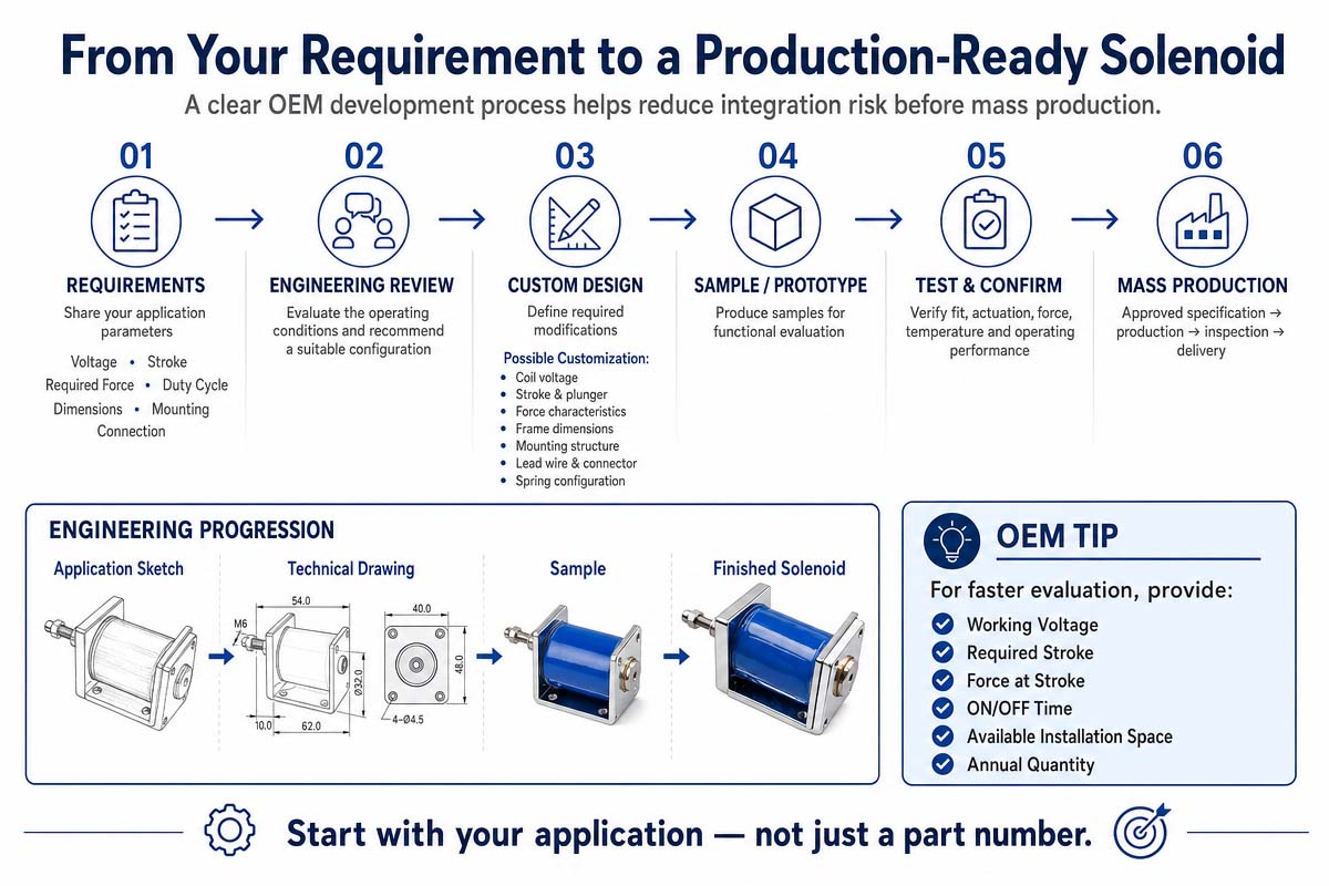
Yes, it can. OEM A Push-Pull C frame solenoid is often customizable in terms of voltage, force, stroke, coil resistance, plunger or shaft geometry, return spring, mounting bracket, lead wire length, connectors, insulation, surface treatment, and noise characteristics depending on the manufacturing capabilities and order volume. Firstly, provide your supplier with application specifications for medical devices, automation equipment, electronic locks, vending machines, and any other specialized product. Before mass production approval, prototype samples of the customized solenoid must be tested in actual operating conditions.

8. What questions to ask a supplier before purchasing a Push-Pull C Frame Solenoid?

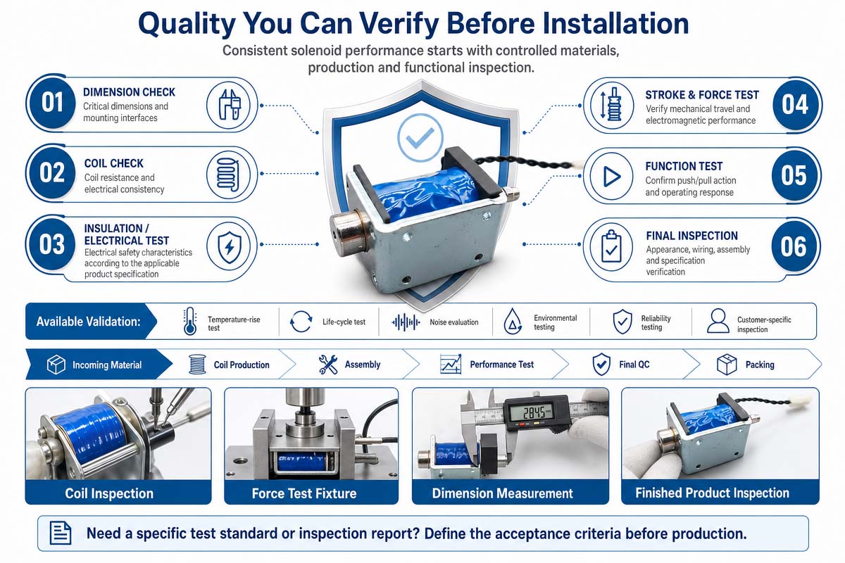
Before placing your order, ask for more than just basic price quote. Ask your supplier to provide you with the force vs. stroke graph, rated voltage, current or power, coil resistance, duty rating, temperature limitations, dimensional tolerances, expected mechanical life, return spring specification and material information relevant to your application.

Talk about the production capabilities, customization capabilities, samples availability, quality controls, lead times and compliance documents relevant to your project. In any case, test your production intent samples at maximum and minimum voltage, hot and cold temperatures, maximum load, maximum cycle rate and conditions which it will operate during its lifetime before approving mass production. For critical OEM projects, do it always.

How to Choose a Push-Pull C Frame Solenoid

The selection of a push-pull C frame solenoid needs to be based on the mechanical requirements of the mechanism and not the coil voltage or size. It is imperative to be precise about the required actuator stroke, response time, and force. Friction is also to be added to the calculations. Return spring is to be added. Gravity needs to be taken into account. Seals should be taken into consideration.

Linkages need to be factored in. Any worst-case load needs to be accounted for. A reasonable engineering margin needs to be included without over-sizing the solenoid, as more heat and higher power consumption, as well as increased cost and impact noise, will result from a larger solenoid.

The Mechanism of Push-Pull C Frame Solenoid

The determination of whether the mechanism needs pull output or push output is then done. The electromagnetical action will draw the plunger into the coil. In a push type, the shaft is such that the plunger movement translates into the outward movement on the opposite working end. Required direction, mounting orientation, start position, return mechanism, and space available need to be checked. Application of side loads to the plunger should be avoided because this will increase friction, wear, sticking, and force variation.

The Force of Push-Pull C Frame Solenoid

The force required needs to be compared against the force versus stroke data of the manufacturer. Maximum force of force near end of travel of the solenoid should not be the only parameter in choosing the solenoid. It is important to note that the most critical point is the initial air gap because magnetic force is lower at longer strokes. Check the needed load against available force at each critical point. In case a return spring is used, its opposing force should be considered while assessing the usable output force.

The coil voltage of Push-Pull C Frame Solenoid

The choice of coil voltage should be made depending on the real power source and driver. The supply tolerance, wiring losses, battery conditions , switching devices have to be accounted for. It is important to examine the coil resistance, current, power, and recommended suppression circuit. Since switching an inductive load causes voltage transients, the driver may need a flyback diode, TVS device, snubber, or some other form of protection. Release speed is influenced by the chosen suppression strategy.

The Duty Cycle of Push-Pull C Frame Solenoid

Duty cycle and temperature are important factors in selecting a solenoid. Maximum on-time, off-time, cycles per minute, ambient temperature, enclosure temperature, and ventilation should be defined. When a coil is designed for intermittent duty and is energized continuously, it will overheat. Additionally, the coil resistance increases with temperature, causing a drop in the current and available force.

The Lifespan of Push-Pull C Frame Solenoid

Life, noise, and environmental requirements should be checked. The total cycles over the product lifetime need to be estimated, and the impact of plunger, stop, spring fatigue, and mounting durability assessed. For making quiet equipment, cushioning, low impact velocity, controlled drive mechanisms, and mechanical damping need to be used. In cases where there are issues of dust, moisture, chemical reactions, or corrosion, a shielded C-frame actuator or different actuator construction is necessary.

The final steps in selecting a solenoid involve the checking of dimensions, mounting holes, shaft interface, connector, lead length, service access, manufacturing tolerances, and assembly sequence. Build a prototype of the selected solenoid in the mechanism and test low and high supply voltage, hot and cold conditions, minimum and maximum loads, misalignment tolerance, repeated cycling, and abnormal operating conditions.

In the case of safety-related or medical equipment, include the solenoid in risk management, verification, electrical safety, EMC, reliability, and other regulatory processes of the product. Select based on measured system performance and not just catalog headline values. Record the operating envelope to ensure that the purchasing, firmware, mechanical, and quality assurance teams stick to the validated design limits during production.

How to Avoid Common Pitfalls in Push-Pull C Frame Solenoid Design

Choosing the correct voltage and nominal force is not enough in designing a successful solenoid. Failures of solenoids in the field are mostly attributed to mechanical integration, thermal considerations, or unrealistic force assumptions.

1. Do not choose the solenoid based on maximum force alone.

Force vs stroke curve always needs to be examined. Solenoids can generate a very high force close to the end position, but not enough force at the beginning of the stroke.

2. Do not forget the return spring.

Actuation: Magnetic force versus Spring force. Net usable force equals magnetic force minus spring resistance, friction, gravity, and other mechanical loads.

3. Do not overload the plunger side.

A solenoid is a linear actuator and not a bearing. Misalignment can cause friction, noise, irregular motion, premature wear, or sticking.

4. Do not neglect duty cycle.

Do not use intermittent duty coils for continuous energizing without considering further effects. Higher on-time will lead to higher winding temperature and decreased reliability.

5. Look for hot coil condition.

Resistance of copper increases with the temperature. Magnetic force will be decreased by current reduction caused by the increasing resistance in the constant-voltage drive.

6. Should account for variation in supply voltage

Should test the actuator at minimum and maximum anticipated supply voltage, not just nominal voltage.

7. Protect the electronic actuator

Solenoid coils are inductive loads. Choose appropriate transient suppression for the switching device. Take into account the effect of the suppression method on release time.

8. Do not use a plunger stop as an uncontrolled hammer.

Repetitive high-speed impact can cause noise, deformation, loose mounting, and accelerated wear. Mechanical cushioning or controlled drive mechanisms may be required.

9. Think contamination.

Open-frame solenoids may be affected by dust, metal particles, liquids, and sticky residues. Shielding or different actuator construction should be considered for harsh environments.

10. Should design for manufacturing tolerances.

Performance of the prototype does not guarantee performance in mass production because of perfect alignment of the sample. Tolerances of the bracket, shaft, spring, linkage, and mounting should be considered.

11. Check the complete cycle.

Should test actuation, hold, release, return, rapid cycling, power interruption, temperature extremes, and worst-case mechanical loads.

12. Unnecessary over-designing.

A larger solenoid solves force problem but creates new problems of heat, noise, power consumption, cost, weight, and packaging.
 

Get A Free Quote Now

Contact Form

Related Products

Related News

Scroll to Top

Get A Free Quote Now !

Contact Form
If you have any questions, please do not hesitate to contact us.
Weilong Solenoid Company Culture
