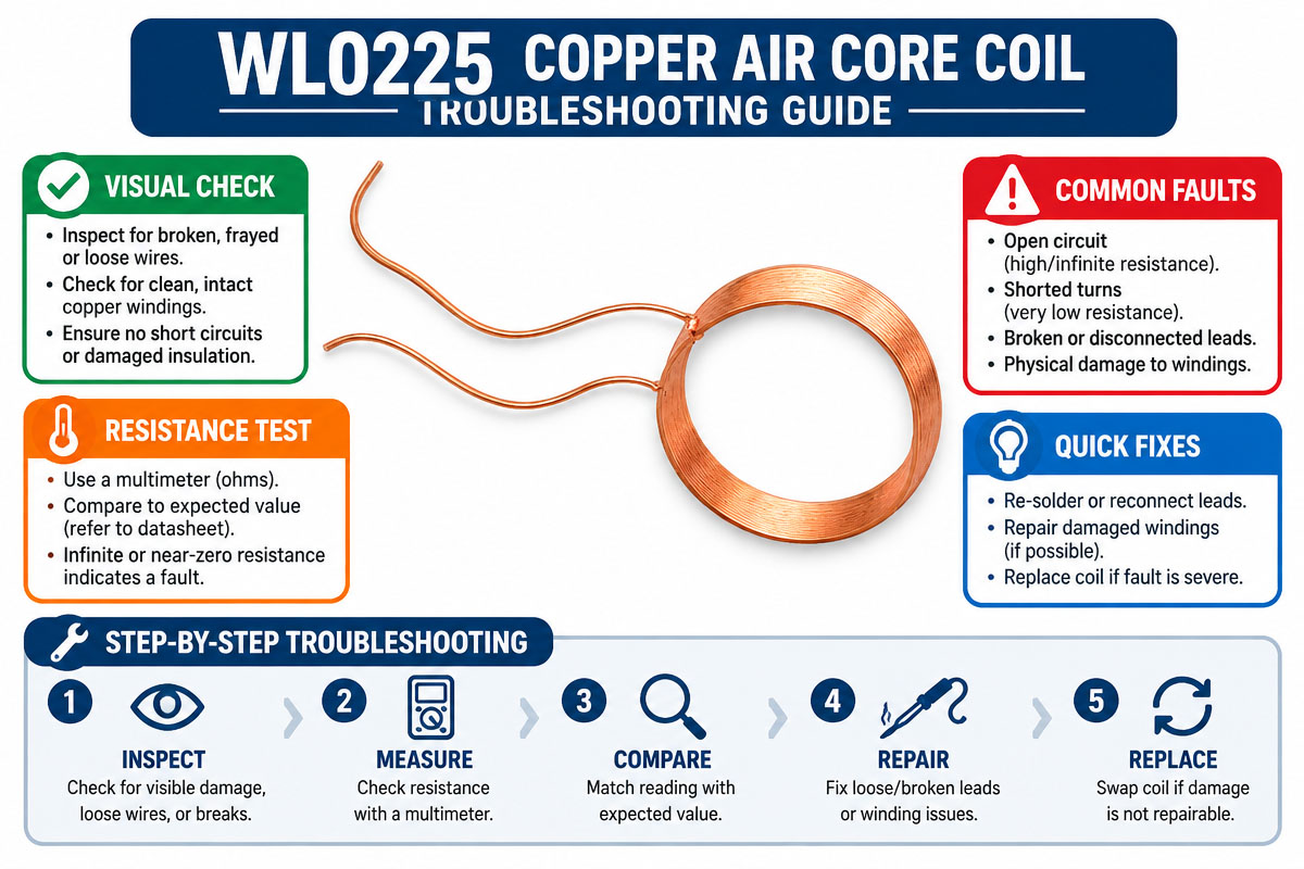
How to Select a Copper Air Core Coil
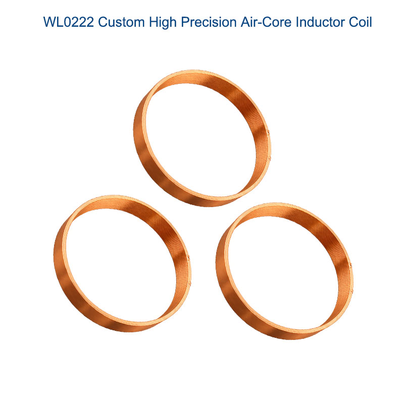
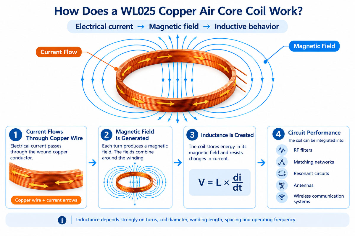
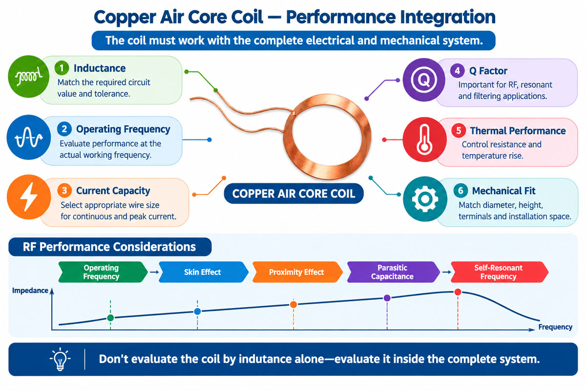
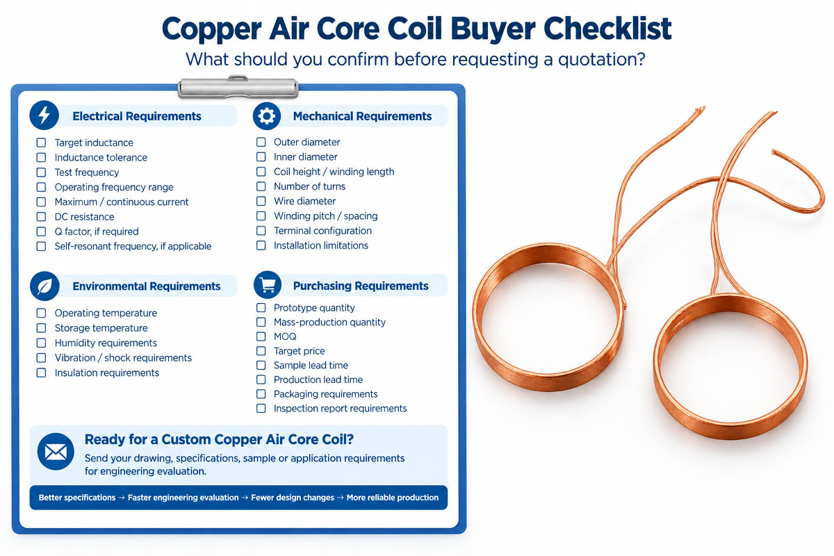
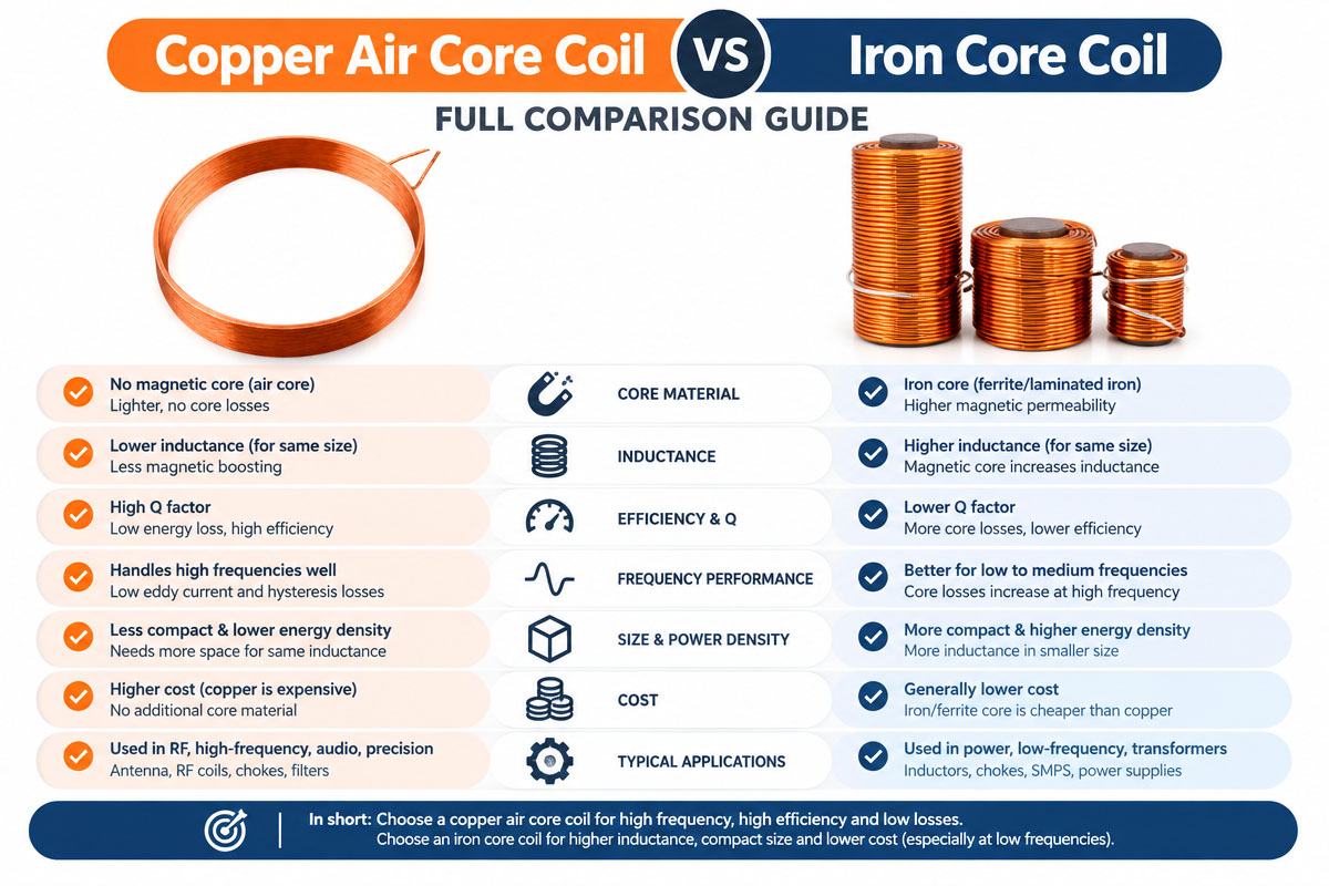
Selection of the appropriate copper air core coil is more than matching a nominal inductance value. One has to take into account the integrated electrical, mechanical, thermal, and manufacturing requirements.
1. Required Inductance Definition
One should start with required inductance and tolerance. For instance, the application requires 10 µH ± 5%. Required tolerance should be confirmed under actual operating frequency and test condition.
2. Operating Frequency
Frequency is an influential factor for the coil’s performance. Due to the skin effect, proximity effect, and parasitic capacitance, a coil designed for low-frequency operation may not perform the same way at RF frequencies.
3. Wire Diameter Selection
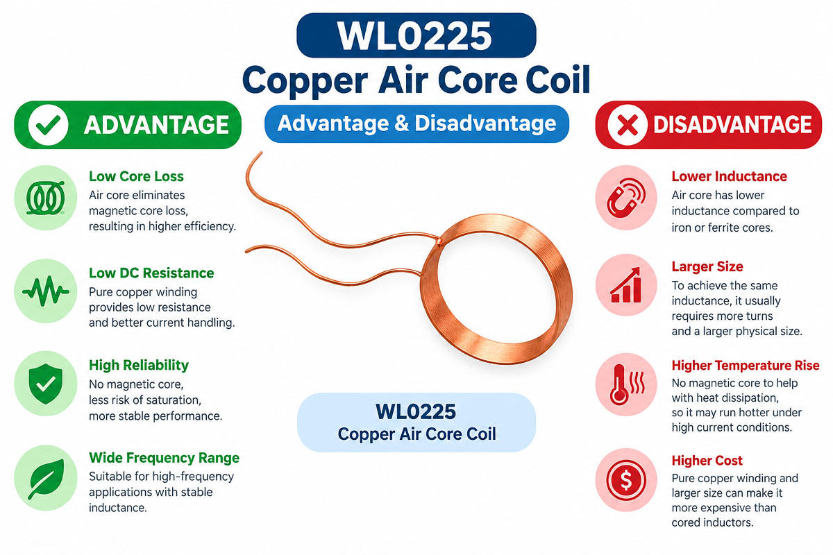
Wire diameter determines the resistance, current-carrying capacity, thermal performance, and physical size. A thicker wire usually provides lower DC resistance but occupies more space during winding.
4. Number of Turns
More turns increase inductance, wire length, resistance, and parasitic capacitance. The optimal number of turns should be calculated but not selected arbitrarily.
5. Coil Dimensions Verification
Outer diameter, inner diameter, length of winding, height, and terminal position. Mechanical tolerances should be marked on the drawing.
6. Existing Conditions Analysis
The maximum peak and continuous current have to be indicated. The manufacturer has to evaluate copper loss and temperature rise at the anticipated operating condition.
7. Q Factor Review
In some cases, the Q factor can be a crucial parameter for RF applications. For resonant and filtering applications, a higher Q factor is desirable. The required Q factor depends on the circuit.
8. Self-Resonant Frequency Verification
All coils have parasitic capacitances. Operating frequency has to be different from the coil’s self-resonant frequency.
9. Environmental Factors
Materials and construction should be chosen depending on temperature, humidity, vibration, insulation requirements, and installation conditions.
10. Production Necessities
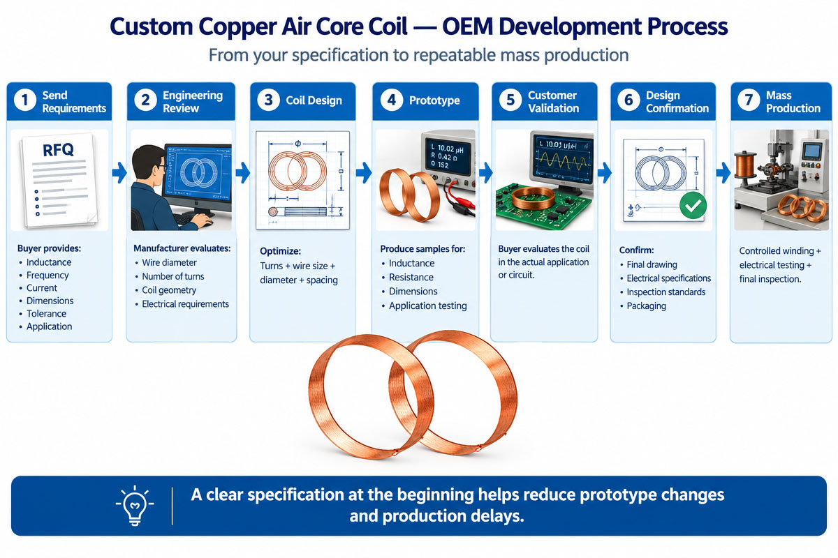
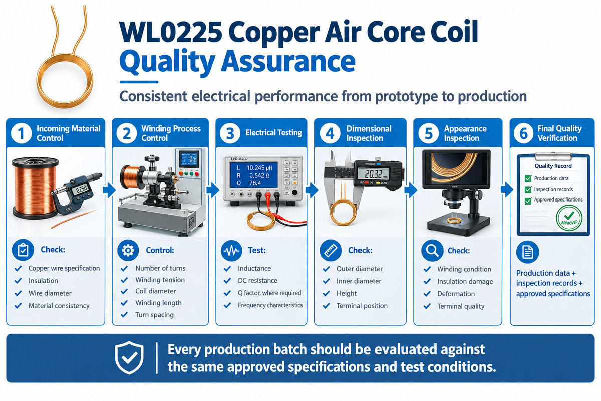
For OEM projects, before the design is finalized, one should verify the quantity, tolerance, inspection method, packaging, lead configuration, and repeatability.
How to Avoid the Common Design Mistakes
Design mistakes can negatively affect the performance or manufacturability of a copper air core coil.
Mistake #1: Inductance Only Specification
Inductance alone is not sufficient. One has to define the frequency, current, resistance, Q factor, and tolerance.
Error 2: No Attention to Operating Frequency
A coil meeting inductance specification at one frequency may not meet it at another frequency.
Mistake 3: Wire That Is Too Thin
Thin wire can increase the resistance and temperature rise, especially in the case of continuous current.
Mistake #4: No Attention to Self-Resonance
At high frequencies parasitic capacitance can significantly influence the coil.
Error 5 – Excessive Winding Density
Too tight winding can cause increased parasitic capacitance and proximity effects. Winding configuration should be chosen based on the application.
Mistake 6: Bad Mechanical Tolerances
Even small changes in diameter, spacing, and length of winding will change the inductance. Thus, tolerance specifications are necessary for critical dimensions.
Mistake 7: Overlooking of Thermal Conditions
Electrical performance should be verified at the real operation temperature, but not only at the room temperature.
Error 8: Design Without Manufacturing Inputs
Theoretical design may not be economically reasonable and stable for mass production. Early communication with the coil manufacturer can help to avoid redesign.
Error 9: Poor Testing Specifications
The drawing should specify the test frequency, method of measurement, tolerance, and acceptance criteria.
Error 10: Selection of the Coil by Size Only
Coils having similar dimensions can have quite different electrical characteristics depending on wire size, the number of turns, spacing, and construction.