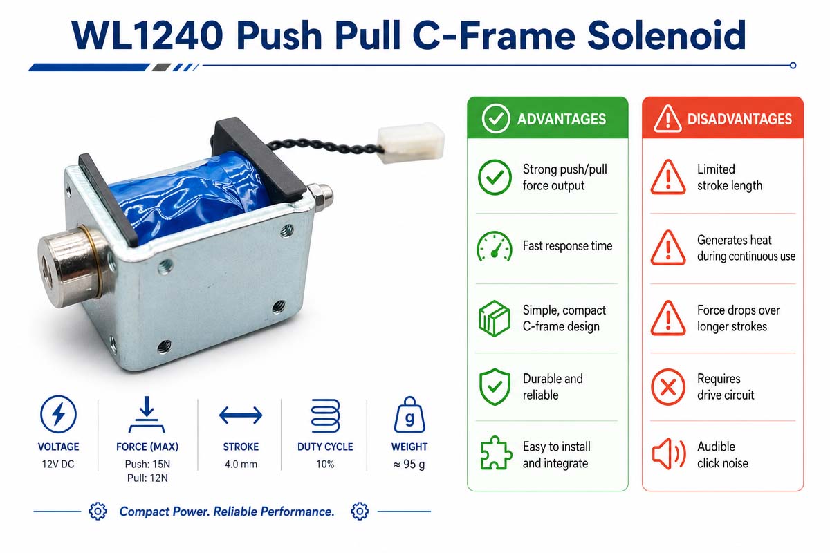
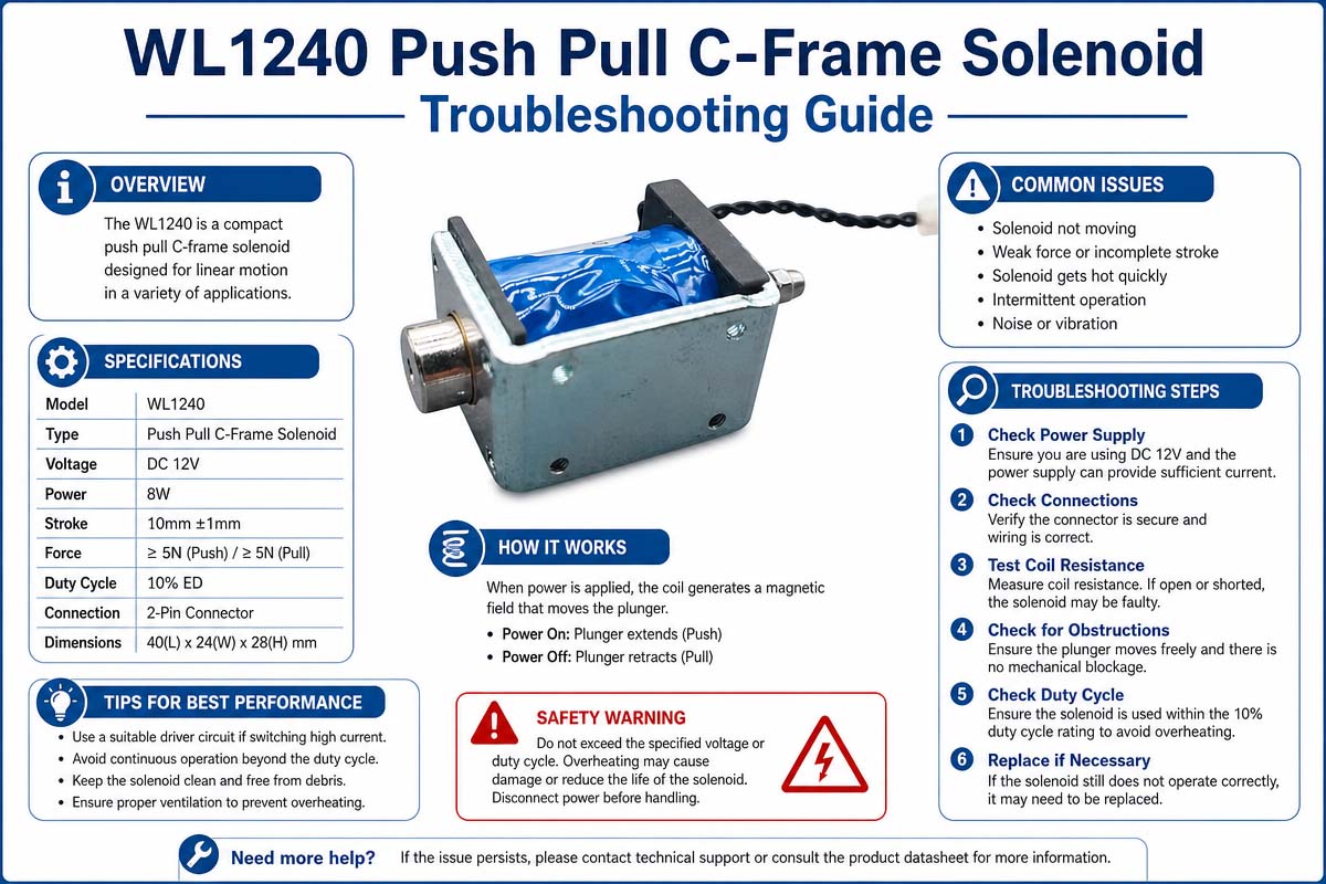
How to Choose a Push-Pull C Frame Solenoid
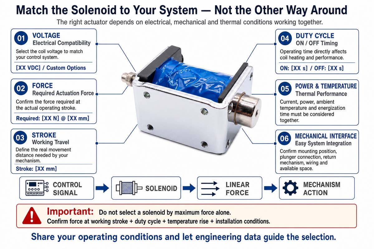
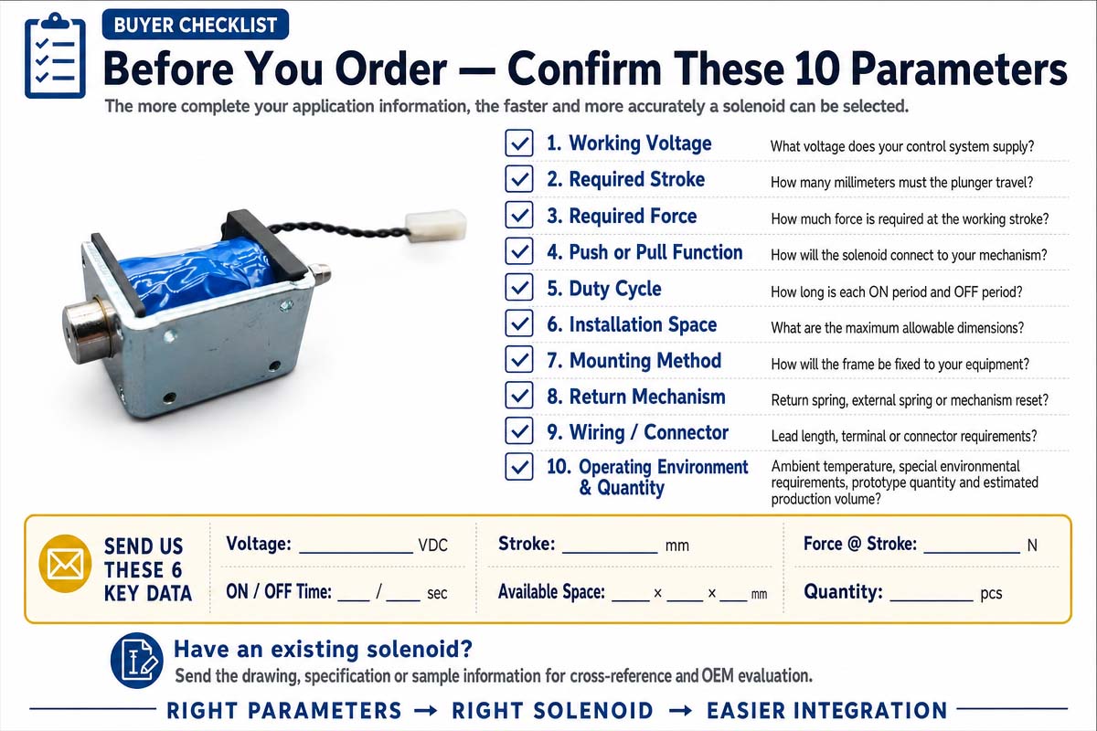
The selection of a push-pull C frame solenoid needs to be based on the mechanical requirements of the mechanism and not the coil voltage or size. It is imperative to be precise about the required actuator stroke, response time, and force. Friction is also to be added to the calculations. Return spring is to be added. Gravity needs to be taken into account. Seals should be taken into consideration.
Linkages need to be factored in. Any worst-case load needs to be accounted for. A reasonable engineering margin needs to be included without over-sizing the solenoid, as more heat and higher power consumption, as well as increased cost and impact noise, will result from a larger solenoid.
The Mechanism of Push-Pull C Frame Solenoid
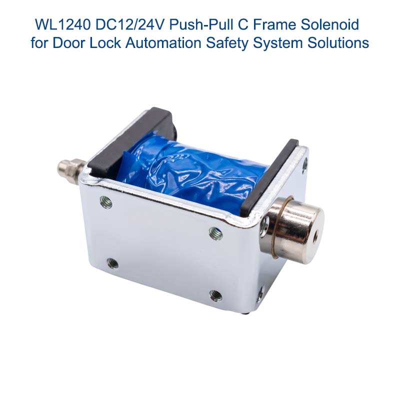
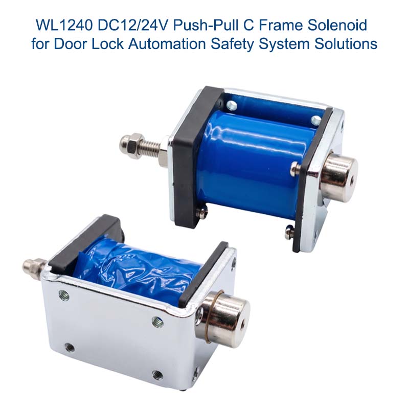
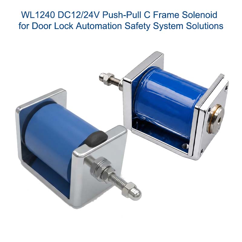
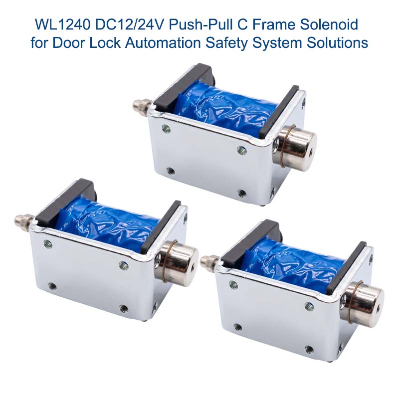
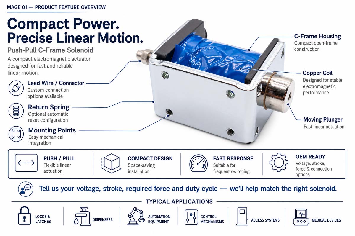
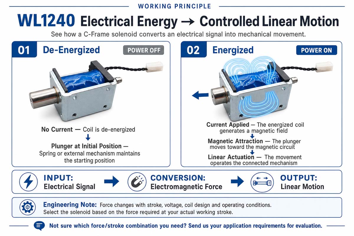
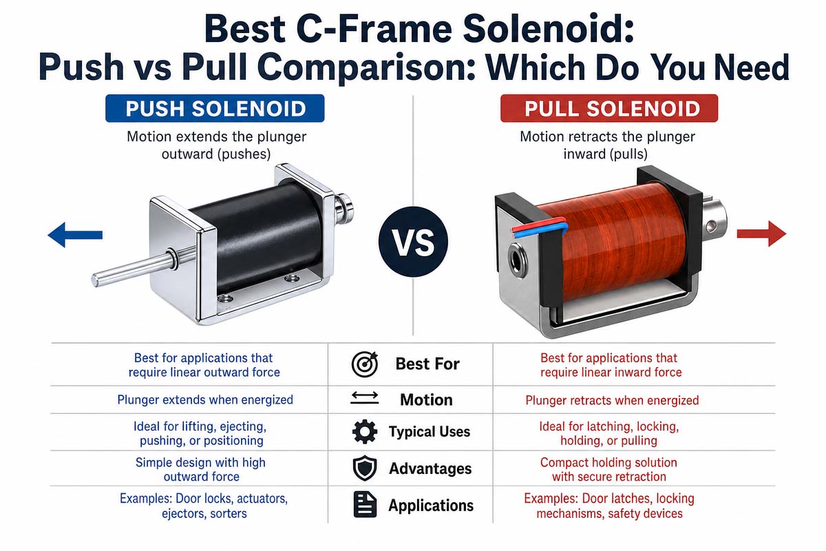
The determination of whether the mechanism needs pull output or push output is then done. The electromagnetical action will draw the plunger into the coil. In a push type, the shaft is such that the plunger movement translates into the outward movement on the opposite working end. Required direction, mounting orientation, start position, return mechanism, and space available need to be checked. Application of side loads to the plunger should be avoided because this will increase friction, wear, sticking, and force variation.
The Force of Push-Pull C Frame Solenoid
The force required needs to be compared against the force versus stroke data of the manufacturer. Maximum force of force near end of travel of the solenoid should not be the only parameter in choosing the solenoid. It is important to note that the most critical point is the initial air gap because magnetic force is lower at longer strokes. Check the needed load against available force at each critical point. In case a return spring is used, its opposing force should be considered while assessing the usable output force.
The coil voltage of Push-Pull C Frame Solenoid
The choice of coil voltage should be made depending on the real power source and driver. The supply tolerance, wiring losses, battery conditions , switching devices have to be accounted for. It is important to examine the coil resistance, current, power, and recommended suppression circuit. Since switching an inductive load causes voltage transients, the driver may need a flyback diode, TVS device, snubber, or some other form of protection. Release speed is influenced by the chosen suppression strategy.
The Duty Cycle of Push-Pull C Frame Solenoid
Duty cycle and temperature are important factors in selecting a solenoid. Maximum on-time, off-time, cycles per minute, ambient temperature, enclosure temperature, and ventilation should be defined. When a coil is designed for intermittent duty and is energized continuously, it will overheat. Additionally, the coil resistance increases with temperature, causing a drop in the current and available force.
The Lifespan of Push-Pull C Frame Solenoid
Life, noise, and environmental requirements should be checked. The total cycles over the product lifetime need to be estimated, and the impact of plunger, stop, spring fatigue, and mounting durability assessed. For making quiet equipment, cushioning, low impact velocity, controlled drive mechanisms, and mechanical damping need to be used. In cases where there are issues of dust, moisture, chemical reactions, or corrosion, a shielded C-frame actuator or different actuator construction is necessary.
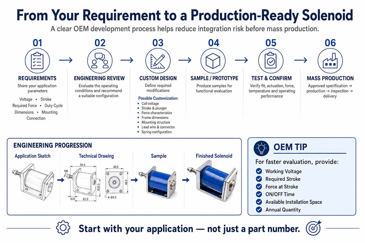
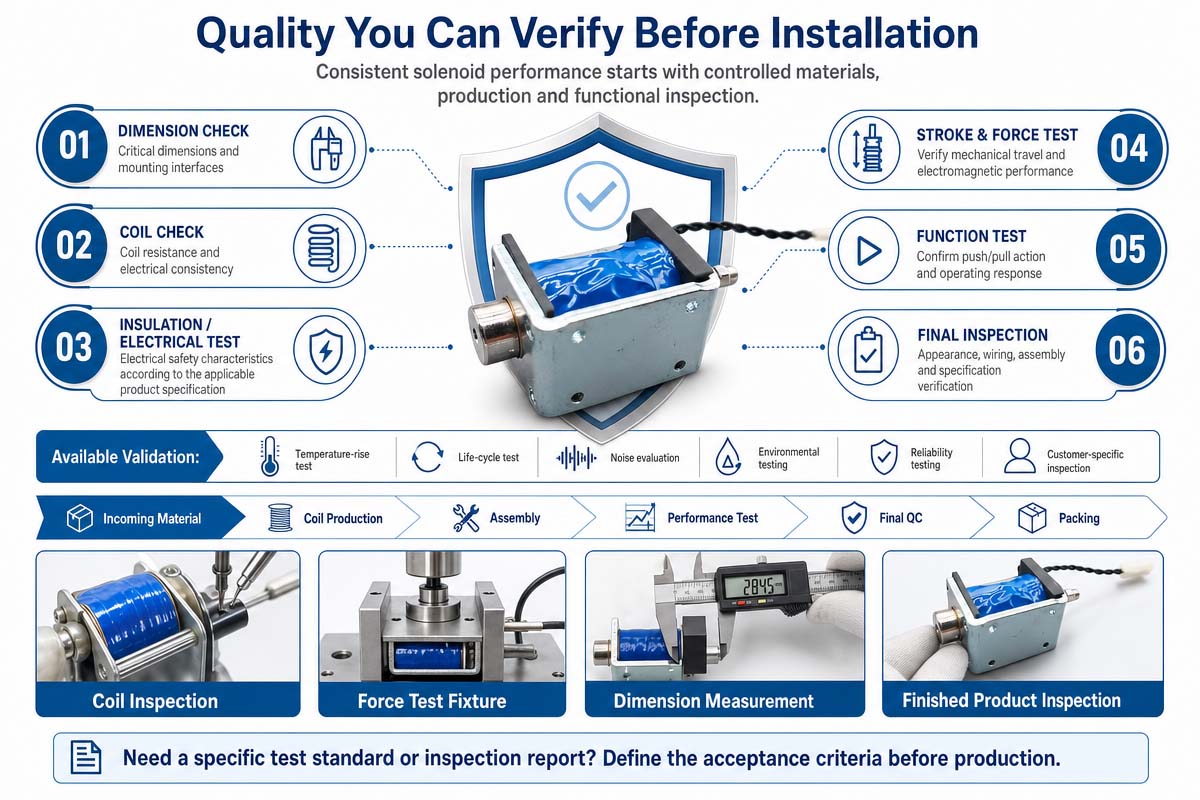
The final steps in selecting a solenoid involve the checking of dimensions, mounting holes, shaft interface, connector, lead length, service access, manufacturing tolerances, and assembly sequence. Build a prototype of the selected solenoid in the mechanism and test low and high supply voltage, hot and cold conditions, minimum and maximum loads, misalignment tolerance, repeated cycling, and abnormal operating conditions.
In the case of safety-related or medical equipment, include the solenoid in risk management, verification, electrical safety, EMC, reliability, and other regulatory processes of the product. Select based on measured system performance and not just catalog headline values. Record the operating envelope to ensure that the purchasing, firmware, mechanical, and quality assurance teams stick to the validated design limits during production.
How to Avoid Common Pitfalls in Push-Pull C Frame Solenoid Design
Choosing the correct voltage and nominal force is not enough in designing a successful solenoid. Failures of solenoids in the field are mostly attributed to mechanical integration, thermal considerations, or unrealistic force assumptions.
1. Do not choose the solenoid based on maximum force alone.
Force vs stroke curve always needs to be examined. Solenoids can generate a very high force close to the end position, but not enough force at the beginning of the stroke.
2. Do not forget the return spring.
Actuation: Magnetic force versus Spring force. Net usable force equals magnetic force minus spring resistance, friction, gravity, and other mechanical loads.
3. Do not overload the plunger side.
A solenoid is a linear actuator and not a bearing. Misalignment can cause friction, noise, irregular motion, premature wear, or sticking.
4. Do not neglect duty cycle.
Do not use intermittent duty coils for continuous energizing without considering further effects. Higher on-time will lead to higher winding temperature and decreased reliability.
5. Look for hot coil condition.
Resistance of copper increases with the temperature. Magnetic force will be decreased by current reduction caused by the increasing resistance in the constant-voltage drive.
6. Should account for variation in supply voltage
Should test the actuator at minimum and maximum anticipated supply voltage, not just nominal voltage.
7. Protect the electronic actuator
Solenoid coils are inductive loads. Choose appropriate transient suppression for the switching device. Take into account the effect of the suppression method on release time.
8. Do not use a plunger stop as an uncontrolled hammer.
Repetitive high-speed impact can cause noise, deformation, loose mounting, and accelerated wear. Mechanical cushioning or controlled drive mechanisms may be required.
9. Think contamination.
Open-frame solenoids may be affected by dust, metal particles, liquids, and sticky residues. Shielding or different actuator construction should be considered for harsh environments.
10. Should design for manufacturing tolerances.
Performance of the prototype does not guarantee performance in mass production because of perfect alignment of the sample. Tolerances of the bracket, shaft, spring, linkage, and mounting should be considered.
11. Check the complete cycle.
Should test actuation, hold, release, return, rapid cycling, power interruption, temperature extremes, and worst-case mechanical loads.
12. Unnecessary over-designing.
A larger solenoid solves force problem but creates new problems of heat, noise, power consumption, cost, weight, and packaging.