

Chapter 1 :What is a Push Solenoid?
A push solenoid is a type of electromechanical actuator which translates electrical energy into linear motion and force. In particular, a push solenoid extends a pushrod to actuate some mechanism or valve in industrial equipment. Push solenoids are indispensable elements of automated machinery because of reliable, rapid and compact linear motion.
In contrast to pull-type solenoids, the former generate force in the direction of extension of their plunger. Push solenoids are available in different configurations – including open-frame, tubular and proportional designs.
Chapter 2 :Push Solenoid Working Principle
The mechanism of operation of a push solenoid is based on the physical principles of electromagnetism. A push solenoid consists of a coil of copper wire wound on a bobbin and an iron plunger positioned inside it partially. When current is applied to the coil, the latter generates a magnetic field, and plunger is magnetized along with the iron circuit around it.
The magnetic flux closes the iron magnetic circuit and travels through the air gap between the plunger and pole piece (stop). The magnetic attraction pulls the plunger into the centre of the coil where the magnetic flux is the strongest. Push solenoid uses the magnetic force for generating linear motion through a pushrod extending from the opposite end of the solenoid.
The force of a solenoid is proportional to the square of current and number of turns of the coil (amperes-turns) and inverse proportional to the air gap distance. With the movement of the plunger and decreasing air gap distance, the magnetic force increases – it is the main peculiarity of the operation of push solenoid, which is important in application design.
Chapter 3 :Why Most Solenoids Naturally Pull

There is a widespread misconception about polarity change in a solenoid making it to push rather than pull. That is not true. A solenoid coil will attract plunger whatever polarity is used. Plunger is always pulled to the centre of the solenoid coil where the magnetic field is the strongest.
This pulling action occurs because of the natural property of magnetic flux to minimize magnetic reluctance of the circuit. Air gap between plunger and pole piece creates the maximum magnetic reluctance in the magnetic circuit, therefore the plunger is pulled towards it.
Chapter 4 :How Engineers Create a Push Solenoid
Engineers use a very simple technique to convert the natural pulling action of the solenoid into a pushing action. In particular, they use a specially designed pushrod.
4.1 Design of Push Rods
The crucial element of the push solenoid is the pushrod. When plunger is pulled into the coil, it pushes the rod which extends from the other end of the solenoid. Peak force of push solenoids occurs when plunger is fully retracted and pushrod is fully extended (contrary to pull solenoid whose peak force occurs at the beginning of the stroke).
4.2 Specific Push Rod Design
To make push solenoids work reliably in demanding industrial applications, engineers have to use special designs of pushrod. At first, solenoids used simple non-magnetic materials such as brass, beryllium copper and plastic for the pushrods to avoid magnetic short-circuiting. However, those pushrods would soon become deformed due to peening and mushrooming under the repeated impacts of plunger.
Nowadays, engineers design pushpins with two pieces made of different materials. The part of pushrod, which contacts the plunger, is made of non-magnetic but highly resistant materials such as stainless steel or beryllium copper. On the other hand, the other end, which contacts the mechanism is made of hardened tool steel. Two pieces are welded to prevent magnetic short-circuiting.
4.3 Push vs Push and Pull
Designers should distinguish the following two configurations:
Push or Pull – the design with symmetrical plunger and pushrod which can perform both functions depending on mounting orientation;
Push and Pull – the design with two coils which can switch the plunger position to provide a bidirectional push and pull action from the same end of the unit.
Chapter 5 :Main Components of a Push Solenoid
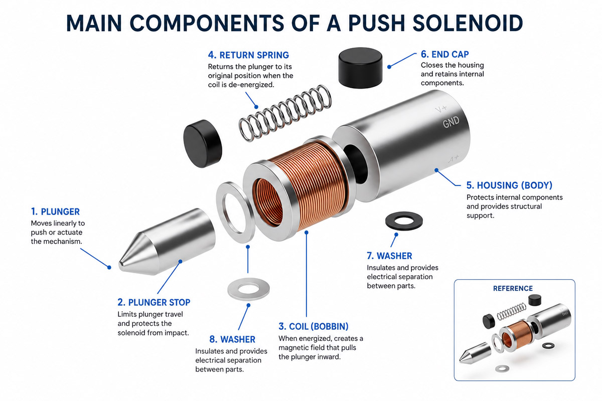
5.1. Coil assembly
Coil is the winding of copper wire on a bobbin. The number of turns, wire gauge and insulation are the important parameters which define the characteristics of the solenoid.
5.2. Plunger (armature)
Movable iron element which is used for converting magnetic energy to mechanical one. Plunger shape (flat face or conical) defines the force-stroke characteristics of a solenoid.
5.3. Frame
Part of a push solenoid which provides the magnetic circuit and structure. C-frame, D-frame and tubular designs are common in industrial applications. The material of frame is highly permeable steel which conducts magnetic flux well.
5.4. Pushrod
Specialized shaft, which converts the plunger motion into the linear pushing action of a solenoid.
5,5. Stop (pole piece)
Iron element of the magnetic circuit which defines the limit of plunger travel. Push solenoids use special stops with a precise hole for the pushrod.
5.6. Return spring
The spring returning the plunger to the initial state when the power source is disconnected. Most push solenoids are spring-return designs but proportional solenoids or application-specific mechanism can be used for the return motion.
Chapter 6 : Push vs Pull Solenoids
| Feature | Push Solenoid | Pull Solenoid |
|---|---|---|
| Motion Direction | Plunger extends outward | Plunger retracts inward |
| Peak Force Location | At full stroke (fully extended) | At beginning of stroke |
| Typical Force Range | 0.11 – 6.3 lbs (varies by size) | 0.18 – 8.75 lbs (varies by size) |
| Key Components | Pushrod through stop | Pull button or attachment on plunger |
| Common Applications | Ejecting, opening, releasing | Locking, closing, holding |
Push solenoids typically deliver slightly lower peak force than comparable pull solenoids because the pushrod must pass through the stop, creating a leak path for magnetic flux.
Chapter 7: Force-Stroke Characteristics
Understanding of force-stroke relation is necessary for successful solenoid application design.
7.1 Inverse Relationship
In any solenoid, the force is inverse proportional to stroke length. Maximum force of the solenoid reduces as stroke length increases. This happens because the force of magnetic attraction is the strongest when the air gap is minimum. For any application, engineer should design for the shortest stroke to maximize the force and reduce the size of a solenoid.
7.2 Stroke ranges
Standard industrial push solenoids are designed to provide stroke lengths up to 0.80 in (20 mm), though there are some solenoids for longer strokes. Stroke range is the key parameter which affects the force output considerably:
Short stroke (2 – 5 mm) – the maximum force output, good for frequent operation
Medium stroke (3 – 8 mm) – conical pole design can be used to improve the force profile
Long stroke (10+ mm) – low force output, requires larger size solenoid or proportional solenoid design
7.3 Force-Stroke Curves
Most of the manufacturers provide force-stroke curves for their push solenoids at different duty cycles. The curves usually demonstrate the decreasing of the force as stroke increases. Engineer has to select a solenoid which gives sufficient force at a certain stroke length with the safety factor not lower than 1.5.
7.4 Duty Cycle
Duty cycle, which is the ratio of on-time to total cycle time, greatly affects solenoid performance and design:
Continuous duty (100%) – solenoid can be continuously energized. Require large coil size to dissipate heat, which results in the lower force for a given solenoid size.
Intermittent duty (25 – 50%) – allow higher power input and force. Provide enough off-time for cooling.
Pulse duty (10% or less) – highest possible force output for a given size. Very short on-time allows the maximum power input.
Chapter 8 : Industrial Push Solenoid Design
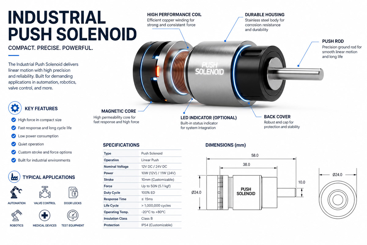
8.1 Temperature control
As the temperature of solenoid increases, the resistance of the coil increases as well which leads to reduction of force output. For a solenoid designed to achieve equilibrium at 85°C, the force calculations should consider this derating. Manufacturers usually provide coil data at 20°C, therefore engineers have to check the force output at the expected temperatures.
8.2 Response time
Response time consists of two parts – time of magnetic flux building (which is more than half of the response time) and the time of plunger travel. Response times vary from 5 milliseconds for small solenoids with short stroke to 250 milliseconds for bigger designs.
8.3 Environmental protection
Industrial solenoids need protection against moisture, oil, dust and vibration. Engineer should choose a proper sealing, coating or special designs for harsh environment.
8.4 Anti-Rotation of the Plunger
If the application requires precise alignment, the anti-rotation feature of the plunger has to be provided to prevent the rotation of the plunger during the actuation. It is especially important if the pushrod has to be aligned with external mechanism.
8.5 Noise and Impact
Solenoids generate noise from plunger impact on the stop. For silent applications, the damping impact absorber or elastomeric bumper should be considered.
Chapter 9 : Manufacturing process of Industrial Push Solenoids
Push solenoids are manufactured using high-precision techniques:
9.1. Coil winding
winding of copper wire with precise tension and layer control to obtain certain number of turns and resistance of the coil.
92. Plunger machining
machining of the plungers from the magnetic steel with tight tolerances. Surface finishing can influence the performance and wear of the solenoid.
9.3. Pushrod fabrication
manufacturing of high-quality pushrods by specialized welding of two parts made of non-magnetic and hardenable steel.
9.4. Frame assembly
stamping or machining of frames with further assembly around the coil. Tubular design uses drawn steel case.
9.5. Final assembly
assembly of all components and testing for force-stroke performance, electrical characteristics and cycle life.
9.6. Customization
modifications of shaft, special terminations, unique plunger shapes, etc.
Chapter 10 : Push Solenoid Industrial Applications
Push solenoids are used in many industrial and commercial devices:
10.1 Actuation of Valves
Push solenoids open and close valves in fluid power systems, including pneumatic and hydraulic systems. In mobile hydraulic systems, push solenoids have to resist harsh environmental conditions and high pressure.
10.2 Automotive and transportation
Push solenoids are used for the engine management system, door locks, HVAC control and transmission shift mechanisms. In the automotive industry, the push solenoids have to be compact, reliable and resistant to extreme temperatures.
10.3 Medical equipment
Push solenoids provide precise motion for diagnostic and therapeutic devices. The medical industry requires the high reliability and long cycle life.
10.4 Automated assembly and packaging
Push solenoids drive the mechanisms of part ejection, position aligners and safety interlocks. The designs with the high cycle life are required in those applications.
10.5 Vending and dispensing equipment
Push solenoids control product dispensing, locks and payment mechanisms in coin-operated and vending machines.
10.6 Agricultural Machinery
Mobile hydraulic applications including the agricultural machinery use push solenoids for valve control and actuation of implements.
Chapter 11: Push Solenoid Selection Guide

When selecting push solenoid for an industrial application, engineer should follow certain procedure:
11.1. Define the functionDecide,
what kind of mechanism is required – push, pull or bidirectional action. In case, if the mounting position of solenoid can be chosen freely, the “push or pull” type of solenoid can be used.
11.2. Specify stroke requirements
Decide, how much stroke is needed. For the best performance, the mechanism should be designed to use the shortest stroke length possible.
11. 3. Calculate the required force
Calculate the necessary force to actuate the mechanism taking into account frictional and loading forces and applying safety factor not lower than .
11.4. Determine duty cycle
Calculate the expected duty cycle: Duty Cycle = (On Time) / (On Time + Off Time) × 100%. This defines whether continuous or intermittent duty is needed.
11.5. Consider the environmental conditions
Evaluate temperature, moisture, vibration and contamination conditions to determine the necessary sealing and protection.
11.6. Choose the power input
Define available voltage supply. Manufacturers provide coils for the standard voltages from 5V to 120V and higher.
11.7. Confirm force-stroke performance
Using manufacturer curves, confirm that the selected solenoid provides the necessary force at the required stroke and duty cycle.
11.8 . Check special features
Take into consideration plunger anti-rotation, special terminations, etc.
Chapter 12: Push Solenoid Advantages and Limitations
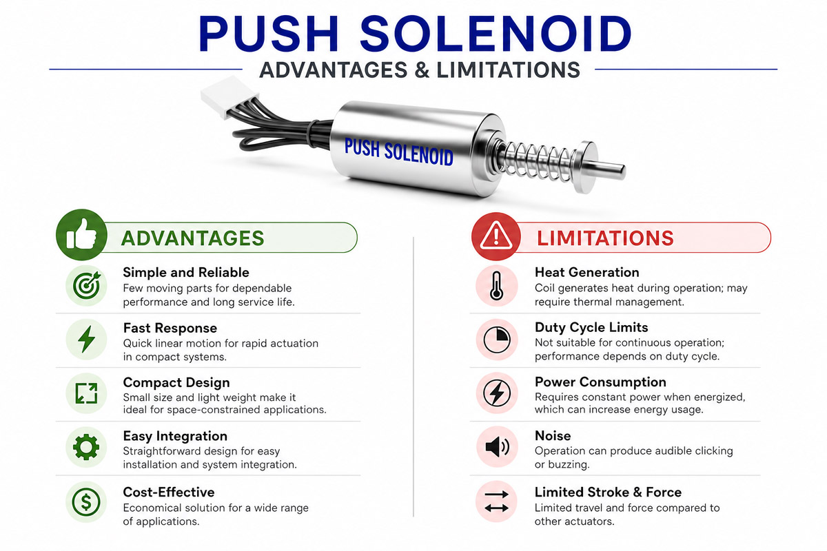
Advantages
• Reliable and robust design
• High speed of response (5-250 ms)
• Low maintenance and long life up to 10 million cycles
• Compact size
• Cost-effectiveness in high volumes
• Multiplicity of configurations
• Ability to operate in harsh environments with proper sealing
Limitations
• Lower force with the increasing of stroke length
• Limited duty cycle due to heat generation
• Influence of residual magnetic fields on release time
• Impact noise can be disturbing
• Need for control circuitry
• Lower push force than comparable pull force
Chapter 13: Frequently Asked Questions
Can I make a solenoid to push by reversing the polarity? No. A solenoid attracts plunger whatever polarity is used. To create pushing action, you have to use pushrod attached to the plunger
Why push force is lower than pull force in comparable solenoids? This happens because the pushrod passes through the hole in the stop which creates additional air gap allowing magnetic flux leakage.
What is the difference between “push or pull” and “push and pull” solenoids? The push solenoid of “push or pull” configuration can work either as a pusher or puller depending on its mounting. The bidirectional “push and pull” solenoid works as push and pull from the same end using two coils.
How long do the industrial push solenoids last? Standard industrial solenoids have lifetime equal 2 million cycles, extended life units last up to 10 million cycles. Lifetime depends on frequency, side load and environmental conditions.
What is the typical response time? Response times range from 5 ms for small units with short strokes to 250 ms for large units. Building up of the magnetic flux takes more than half of response time.
Chapter 14 : Conclusion
Push solenoid is widely used building blocks of industrial automation providing reliable, rapid and compact linear motion. Knowing the basic engineering principles of such actuators from natural pulling action of solenoids to pushrod design allows designing effective solenoid applications.
Considering force-stroke requirements, duty cycles and environmental conditions, engineer can select or design push solenoids which will provide excellent performance in the demanding applications. Modern push solenoids provide high performance, with lifetime up to 10 million operations and response time of several milliseconds.
From hydraulic valve to the ejection mechanism or automated production line – push solenoid is a proven reliable and cost-effective solution for your application. Following the principles described in this article, you will easily find an appropriate push solenoid design.


