
How to Choose a Compact Solenoid Coil
The proper choice of the compact solenoid coil starts with the valve and the real operating conditions, not just with external dimensions of the coil. First, check the voltage rating and whether the system is DC or AC. 12VDC, 24VDC, 24VAC, 110VAC, or 230VAC are common for industrial systems. The coil has to be selected in accordance with the real supply voltage and voltage tolerance.
Second, check the power, resistance, current, and duty cycle of the coil. If a valve operates continuously, the coil has to be designed as continuous-duty and has to dissipate the heat. Larger power can be utilized for strong actuation, but it is possible only for intermittent operations. Allowed on time cannot be exceeded.
Third, check the mechanical interface. The coil has to be exactly the same as the valve assembly in diameter, height, mounting, valve tube size, armature geometry, and connector location. If a compact housing is not interfering with the neighboring components, it becomes useless.
Fourth, check the surrounding environment. Ambient temperature, fluid temperature, vibrations, shocks, dust, moisture, oil, chemicals, and outdoor exposure have to be taken into account. The proper insulation class, encapsulation material, connector sealing, and ingress protection have to be selected.
Fifth, check the magnetic force and response time. Coil, armature, air gap, spring force, and hydraulic or pneumatic loads are the elements of the electromagnetic system. A weak actuation problem cannot be solved just by changing the coil.
Additionally, measure the temperature rise in case the coil reaches thermal equilibrium. Measure current, surface temperature, behavior, and performance of pull-in and holding.
A design that operates for a short time at room temperature may fail after long-term operation in an enclosed environment.
Finally, take into account the connector type, cable direction, polarity protection, surge protection, certification requirements, serviceability, and expected production volume. For OEM machines, provide the coil manufacturer valve drawings, voltage, power target, duty cycle, temperature range, dimensional requirements, connector requirements, and application details. Prototype testing is strongly recommended at the worst-case voltage and temperature operating conditions before the final production.
Guidelines for Avoiding Common Compact Solenoid Coil Design Pitfalls
Typical design mistakes of common compact solenoid coils occur because of the coil being considered as a standalone element. Coil, armature, tube, air gap, spring, valve load, power supply, and ambient temperature have to be considered as a system.
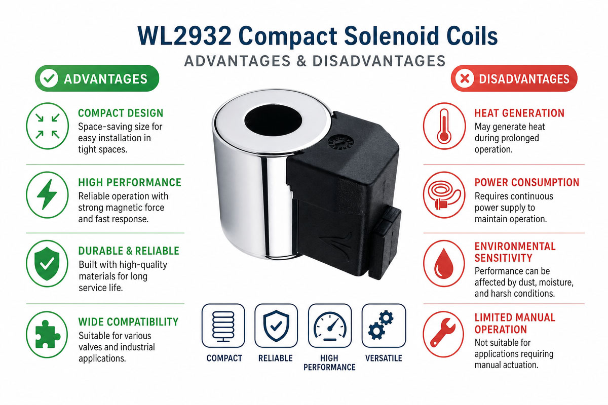
Do not reduce coil size before checking the thermal limits. The smaller winding may be overheated, especially during continuous-duty operation.
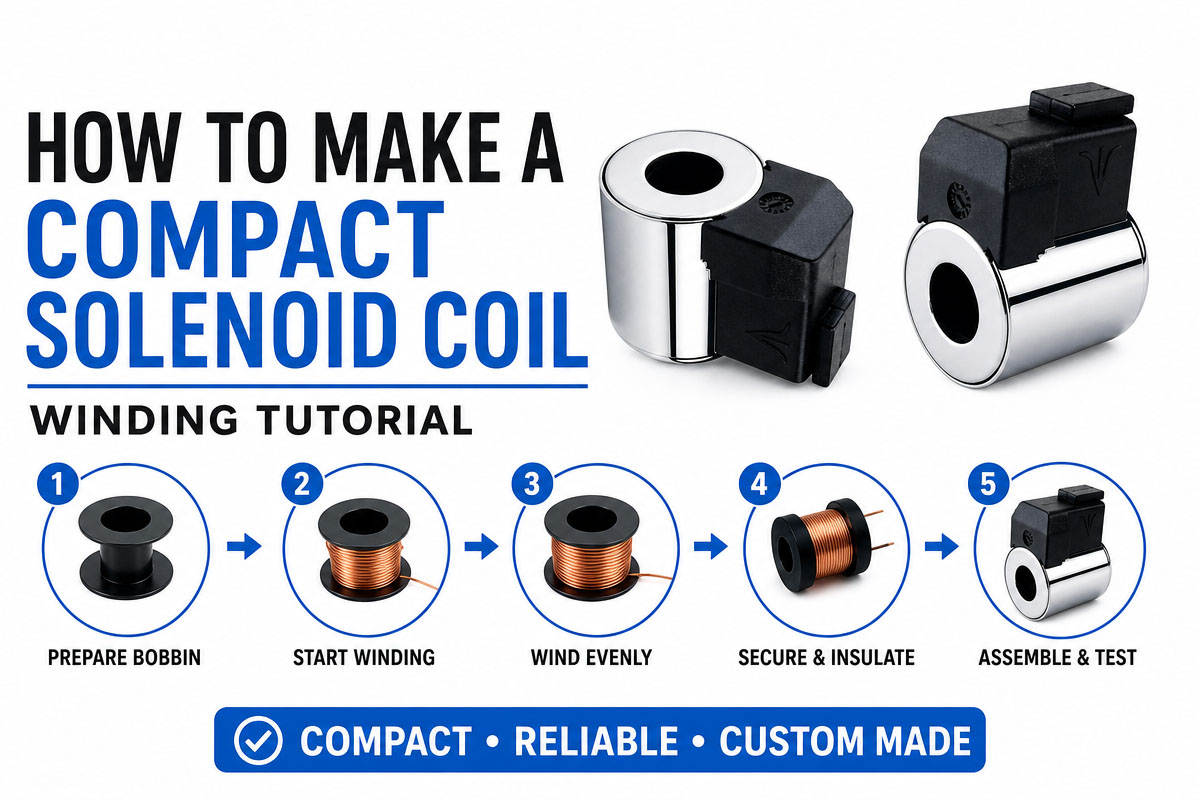
Do not select the wire diameter just because of the convenience of winding. All parameters such as resistance, current density, turns, fill factor, voltage, and target ampere-turns have to be calculated.
Do not overstuff with windings. The space is needed for insulation thickness, manufacturing tolerances, wire expansion, and resin or encapsulation.
Do not forget about the air gap. The even slight increase in the magnetic gap can reduce available force.
Match the bobbin and insulation system to the temperature. Check insulation class, winding temperature, ambient temperature, and hot spot margin.
Do not forget about voltage tolerance. Do not test only at nominal supply voltage; test also at minimum and maximum supply voltage.
Design for the real duty cycle. A coil designed for short intermittent duty may be overheated during continuous energization.
Take care about connector orientation in advance. Even a compact coil can create assembly problems with the neighboring valves because of improper plug location.
Consider vibrations, moisture, oil, chemicals, and pressure washing in heavy-duty machines.
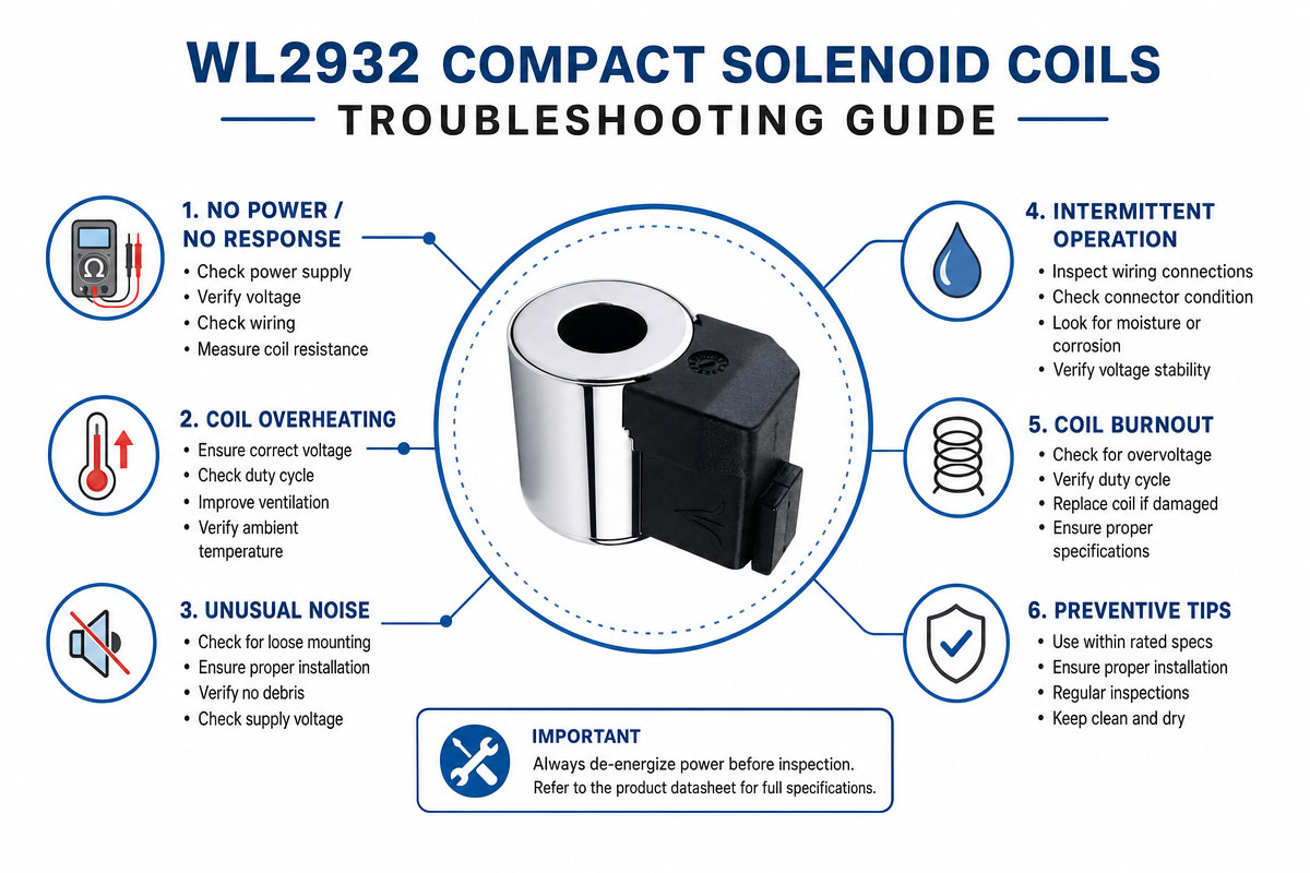
Create the complete valve assembly prototype. Test the pull-in, holding force, current, resistance, surface temperature, and response after thermal stabilization.
The safe design procedure includes electromagnetic calculations, thermal verification, tolerance analysis, prototype winding, and application testing before the mass production.