C Frame Push-pull Solenoid for Modern Appliance Designs
C Frame Push-pull Solenoid for Smart Mechanical Systems
C Frame Push-pull Solenoid for Smart Product Automation
C Frame Push-pull Solenoid for Linear Motion Automation
C Frame Push-pull Solenoid for Compact
C Frame Push-pull Solenoid for Precision Device Control
C Frame Push-pull Solenoid for Modern Appliance Designs
C Frame Push-pull Solenoid for Smart Mechanical Systems
C Frame Push-pull Solenoid for Smart Product Automation
C Frame Push-pull Solenoid for Linear Motion Automation
C Frame Push-pull Solenoid for Compact
C Frame Push-pull Solenoid for Precision Device Control

WL0420 C Frame Push-pull Solenoid for Medical Automation Solutions

The C Frame Push-Pull Solenoid is a compact electromagnetic actuator with an open C-shaped steel frame, designed to provide a controlled linear motion. The solenoid converts the electrical energy into the linear mechanical motion with the help of the plunger pulled into the operating position by a magnetic field of a copper winding. After the power removal, the plunger is returned to its starting position by a spring or other external force. The output can be pulling and pushing, and the device can be used for such purposes as locking, unlocking, dispensing, switching, latching, and positioning of various elements.

The typical applications of C Frame Push-Pull Solenoids are smart home devices, vending machines, electronic locks, printers, dispensers, office devices, control panels, and small automation devices. Choosing the right solenoid: pay attention to such parameters as voltage, stroke, force, duty cycle, response time, coil temperature, mounting space, and service life. Such features as customized shafts, springs, connections, and coils can be helpful in solving OEM and assembling problems.

C Frame Push-pull Solenoid Product Overview

The C Frame Push-pull Solenoid is an efficient linear actuator for small electrical and electromechanical devices. The assembly includes a C-shaped steel frame, copper winding, a fixed magnetic core, a movable plunger, a shaft, and a return spring. When the solenoid is energized, it creates a fast linear stroke to actuate a latch, lever, gate, valve, or release mechanism. The options include different voltages, forces, strokes, duty cycles, wire lengths, connectors, spring rates, and mounting dimensions. The C Frame Push-Pull Solenoid can be customized for OEM applications according to the available space, target force, operating frequency, noise requirements, temperature limitations, and mechanical life.

How Does a C-Frame Push-Pull Solenoid Work? 

The push-pull solenoid C frame works on the principles of electromagnetic fields generated by a current flowing in the copper coil. When a DC supply is applied to a winding, current starts flowing in the coil, creating a magnetic field. The magnetic field attracts the movable plunger to the position where the air gap is minimum, creating a linear motion.

If the output shaft is on the same side as the plunger, then the device is used to create a pulling action. Otherwise, the same inward motion of the plunger creates a pushing action.

After the power removal, the magnetic field is collapsed, and the plunger is returned to its original position by a return spring, gravity, or the external force.

The force produced by the C Frame Push-Pull Solenoid is not constant. At large air gaps the force is small and grows closer to the seated position of the plunger. The performance will depend on the current in the coil, the voltage, the resistance, the stroke, the air gap, the spring force, the temperature, and the duty cycle.

C-Frame Push-Pull Solenoid Basic Features

Compact design, quick linear response, easy mounting, and versatile push/pull output are the basic features of the C Frame Push-pull Solenoid. An open-frame design reduces the material costs and makes the assembly more economical. One can customize various options depending on the product requirements, such as voltage, stroke, plunger shape, springs, lead wires, connectors, and mounting. The solenoid provides strong short-stroke actuation with simple electrical control using switches, relays, MOSFETs, and control boards. The other features include repeatable motion, adjustable holding force, different duty cycles, and compatibility with latching, locking, dispensing, switching, valve, and appliance automation mechanisms.

C Frame Push-pull Solenoid Product Video

C Frame Push-pull Solenoid Product Detailed Display

C Frame Push-pull Solenoid Technical Datasheet

Brand Weilong Technology Model Number WL0420 C Frame Type
Rated Voltage (V) DC 3–24V Rated Power (W) 3-10 W
Work Model C-Frame Type Design Holding Force (N) 10-30 Gf
Stroke (mm) 1-3 MM Reset Time(s) 50 Ms
Service Life 300 Thousand Times Certification CE, RoHS, ISO9001
Material Carbon Steel Housing with Zinc-Plated Coating Lead Wire Length (mm) 200
Install Style Adjustable Screw Tolerance of Dimension ± 0.1 MM
Water-proof None Insulation Class F 155 Cel. Degree
Hi-Pot Test AC 600V 50/60Hz 2s Non-excitation Holding Force 0
Working Temperature -10°C-100°C Duty Cycle 1-100%
Thread Depth (mm) / Payment Term TT, or LC at Sight
Sample Order Yes. Warranty 1 Year
MOQ 500 pcs Supply Ability 5000 pcs per week
Delivery Time 30 Days Port of Loading Shenzhen

What is the difference between a C-frame push-pull solenoid and a D-frame push-pull solenoid

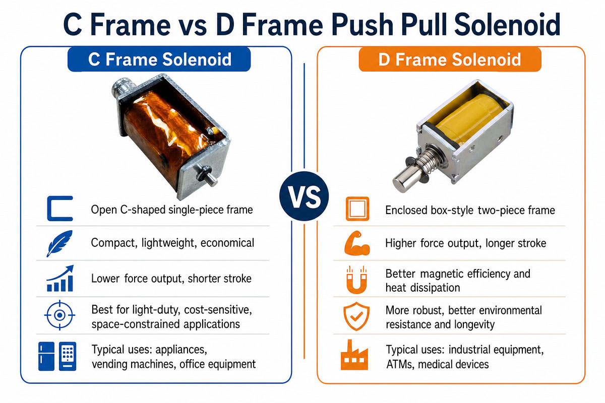
The difference between the C Frame vs D Frame Push Pull Solenoid

Both C-shaped and D-shaped solenoids perform conversion of electrical energy into linear motion; however, they have different frame structures. While in standard open designs a C-shaped frame has a formed metal frame around part of the coil, making the assembly partially open, in the D-frame design there is more steel around the coil, forming a more closed mechanical and magnetic structure.

Comparison C-Frame Push-Pull Solenoid D Frame / Box Frame Solenoid
Frame construction Open C-shaped frame More enclosed frame construction
Typical cost Lower Usually higher
Structure Simple More robust
Size and weight Compact and lightweight May use additional frame material
Magnetic circuit More open More enclosed magnetic path
Force efficiency Good for general applications Can provide better efficiency for comparable designs
Mechanical protection Lower Better protection around the coil
Mounting Simple and flexible Typically more rigid
Heat exposure Open structure allows airflow. Depends strongly on frame and coil design
Dust protection Requires protection from host product Usually somewhat better mechanically protected
Customization Easy for high-volume OEM projects Also customizable
Typical applications Appliances, locks, dispensers, office equipment Higher-demand equipment, locking systems, industrial devices
Best suited for Cost-sensitive compact mechanisms Applications prioritizing rigidity or stronger magnetic structure

Which Should You Pick?

If you need a compact size, economical pricing, easy installation, and short stroke actuation, you should opt for C Frame push-pull solenoids. This type is suitable for consumer appliances, smart home equipment, dispensers, electronic locks, office machines, and high-volume OEM products.

If you need a more closed magnetic structure, more mechanical rigidity, better protection of the coil, or better force efficiency, you should choose a box-frame or D-frame solenoid.

Not all the manufacturers use the D-frame, box-frame, and sometimes O-frame terms in the same way. Therefore, rather than choosing the solenoid by the frame name, one should compare the mechanical drawings, force-stroke graph, coil specifications, duty cycle, and environmental protection.

C Frame Push-pull Solenoid Industrial Application

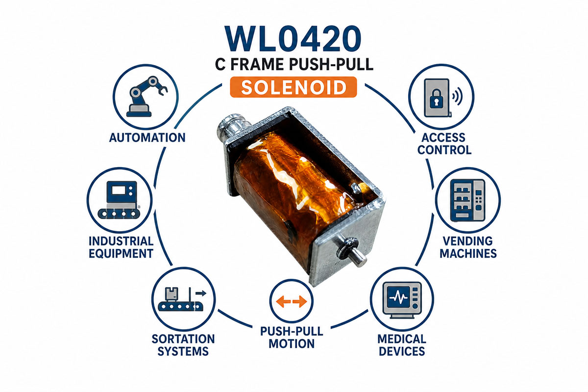
WL0420 C Frame Push-pull Solenoid Industrial Application

C-frame push-pull solenoids are used when there is a need for short and fast electrically controlled linear movement. In smart appliances they are used to control locks, lids, detergent dispensers, dampers, release mechanisms, water flow components, and safety interlocks. These can be used in vending and dispensing machines for releasing products, activating gates, moving shutters, or controlling coin and payment mechanisms. The electronic locks and access control devices use C Frame push-pull solenoids to engage and release bolts and latches. Other office devices such as printers and scanners use them for paper handling, clutch control, switching, or positioning.

These solenoids are used in industrial and commercial automation equipment when a compact actuator is needed to operate a lever, valve, stopper, latch, or selector. The custom solenoids can be used for noncritical positioning or release functions in small medical, laboratory, and testing devices if they meet the applicable product standards. The controlled locking or switching mechanisms in automotive and other mobility-related products can be similar actuators if the environmental requirements are taken into account.

When choosing the solenoid, one should take into account the force-to-stroke ratio, the operating voltage, the duty cycle, coil temperature, mounting space, noise, and expected service life under the operating conditions.

The Increasing Popularity of C-Frame Push-Pull Solenoids in Smart Appliance Automation

C-Frame push-pull solenoids become increasingly popular in smart appliance automation due to the ability to solve a very practical design problem—conversion of low-voltage electrical signals into quick mechanical action. Smart appliances have more electronically controlled locks, lids, dispensers, vents, valves, safety interlocks, and release mechanisms than conventional products. Many of them require a short linear stroke rather than a complicated motor system.

The C-shaped solenoid attracts the designer with its compactness, relative cheapness, ease of control from the PCB, and easy incorporation into high-volume products. The solenoid can quickly respond to the signals from sensors, microcontrollers, relays, or IoT control systems. Manufacturers can also customize the voltage, stroke, shaft configuration, spring force, connectors, mounting, and noise-control features.

Another reason for the popularity of the C-shaped solenoid is its simplicity. A solenoid can have fewer mechanical parts than a geared motor for a binary action (lock/unlock, open/close, release/reset, and engage/disengage).

However, a solenoid is not always the optimal actuator for smart appliances. Applications that require long travel, proportional positioning, extremely quiet movement, or continuous holding may be better served with motors, latching actuators, stepper actuators, or other motion-control technology.

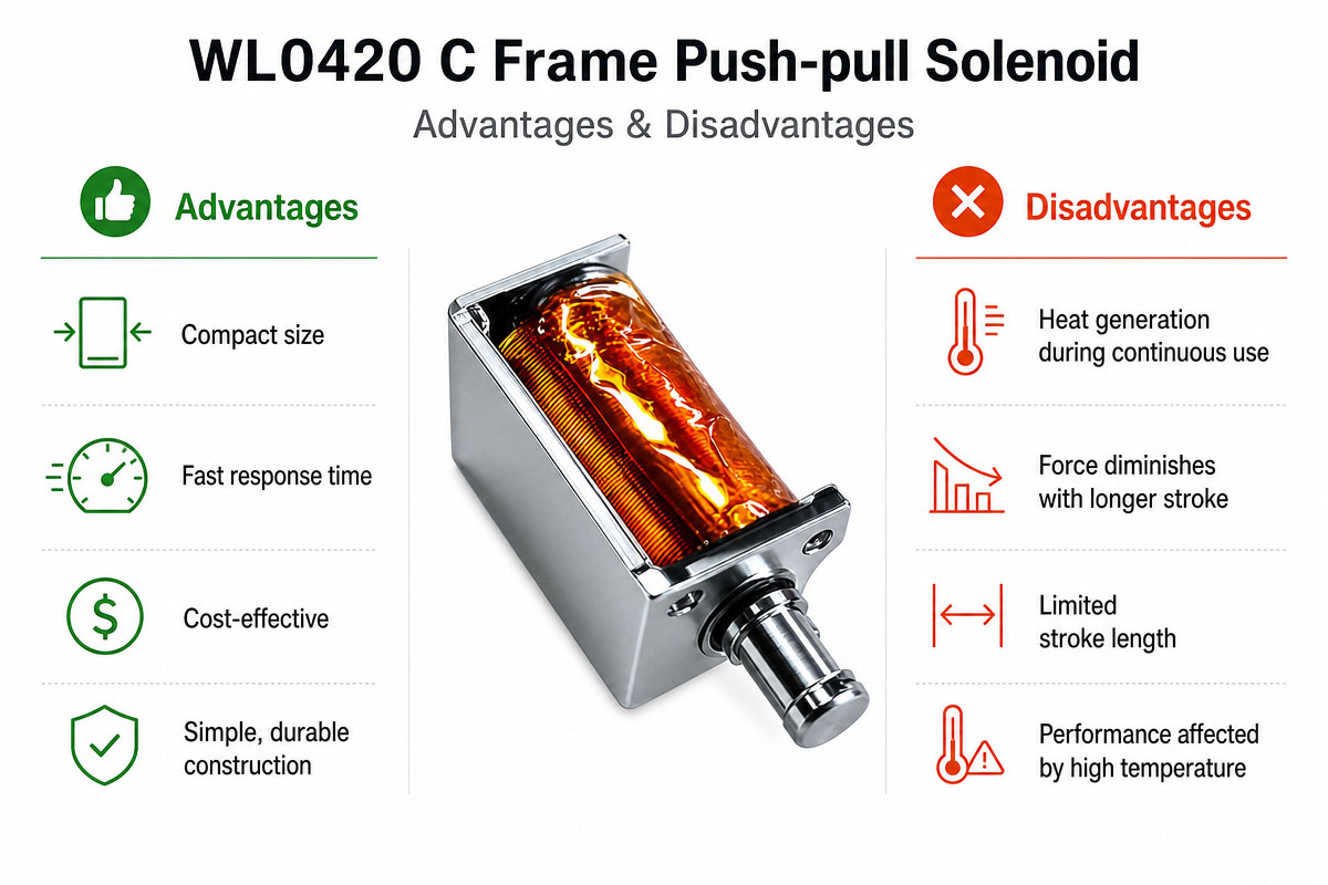
C Frame Push-pull Solenoid Advantage and Disadvantage

C Frame Push-pull Solenoid Pros and Cons

One of the main advantages of the C Frame Push-pull Solenoid is its simple, compact and economical structure. The open steel frame implies fewer components than an enclosed magnetic housing which can lead to reduced weight, costs and installation. It can easily be mounted, tuned and is perfect for quick short stroke linear actuation. Voltage of the coil, direction of the shaft, stroke, strength of the return spring, connectors, mounting holes, and lead wires are specifically designed to fit a wide range of OEM products. Open structure may also be beneficial in providing convenience for assembly and heat dissipation.

The same open structure of the product causes most of the disadvantages. A C-shaped frame design provides less protection to the coil and moving parts than the enclosed design. If the finished product is not protected enough, it becomes vulnerable to dust, moisture, side loading, impacts, and misalignment during assembly. The magnetic efficiency and rigidity may also depend on the design. The impact noise can be heard when the device operates at high speed. Like any other non-latching solenoid, it uses energy during the process of operation and creates heat. Therefore, if it works in the continuous mode, high duty cycle, or high ambient temperature, thermal verification and electrical control are necessary.

C-Frame Push-Pull Solenoid Problem Solving

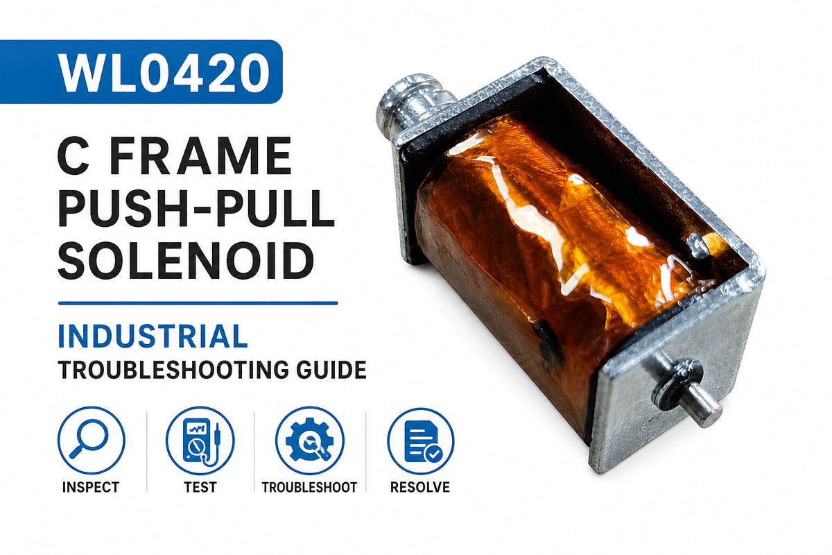
C Frame Push-pull Solenoid Industrial Troubleshooting Guide

In order to solve problems with a C Frame push-pull solenoid, one needs to check the power supply. First of all, it is important to verify the voltage in the coil while the solenoid is powered. It is also necessary to check whether the driver supplies enough current. If the solenoid does not work, it is important to check the wiring, contacts of the connector, continuity of the coil, output of the driver, and jamming or side loading of the plunger.

If the force is too weak, it means that either the working stroke is too long, the voltage of the supply drops under load, the spring is too stiff, or more force is required. Note that the force generated by the solenoid is highly dependent on the air gap.

If the coil becomes overheated, the engineer needs to check the duty cycle, on-time, operating frequency, ambient temperature, and applied voltage. The coil is designed for intermittent use, not continuous.

Slow, noisy, or inconsistent movement indicates such problems as dirt, burrs, shaft friction, loose mounting, impact surfaces, and tolerance stack-up. One needs to make sure that the plunger moves freely without rubbing. If there are failures in the solenoid after cycling several times, it is necessary to check the wear, spring fatigue, loose connections, and coil insulation. One should always thoroughly test the solenoid in the final assembly.


C Frame Push-Pull Solenoid FAQs

1. What is C Frame Push-Pull Solenoid?

C-Frame Push-Pull A solenoid is an electromechanical actuator that creates linear movement upon the application of electrical power. The open C-shaped metal frame provides a compact and economical structure. A plunger can be used either for push or pull action depending on the design. Solenoids are suitable for locks, vending machines, appliances, automation equipment, and other electromechanical devices.

2. How does C Frame Push-Pull Solenoid work?

When the voltage is supplied to the solenoid’s coil, it creates an electromagnetic field. This field pulls the movable plunger in the direction of the coil, generating linear movement. When the power supply is off, the plunger usually returns to the initial position due to a return spring or external mechanical force. The force available depends on voltage, current, coil design, stroke length, and duty cycle.

3. What are the voltages of C Frame Push-Pull Solenoids?

Common voltages are 5V, 6V, 12V, 24V, and 48V D.C. However, other voltage options can be customized for specific applications. The voltage has to correspond to the power supply and the required operating force. Overvoltage causes overheating and reduces the service life of the solenoid.

4. Which C Frame Push-Pull Solenoid should I choose?

The selection criteria are operating voltage, stroke, output force, duty cycle, installation space, response speed, and environmental conditions. It is particularly important to estimate the required force at the maximum working stroke, as the force generated by the solenoid reduces with increasing air gap. Other options are custom plungers, springs, wire length, connectors, and mounting.

5. Can a C Frame Push-Pull Solenoid operate continuously

It depends on the coil design and duty cycle of the solenoid. There are solenoids designed for continuous operation, and there are solenoids for intermittent or short-time operation. The short-duty solenoid must be supplied with short pulses, as the temperature of the coil rises to unacceptable levels. It is always necessary to check the rated duty cycle before integration.

6. Why does the C Frame Push-Pull Solenoid get hot during operation?

Heat is usual, as the coil has resistive losses due to the electric current passing through it. The temperature rise depends on the voltage, current, duty cycle, ambient temperature and ventilation and mounting conditions. Overheating may be caused by overvoltage, wrong duty cycle, insufficient cooling or wrong solenoid choice.

7. What are the applications of C Frame Push-Pull Solenoids?

The C Frame Push-Pull Solenoids find extensive use in intelligent appliances, electronic locks, vending machines, office equipment, gaming machines, medical equipment, industrial automation, dispensing systems, sorting mechanisms, access control devices and other small electromechanical systems requiring fast and repeatable linear movements.

8. Can C Frame Push-Pull Solenoids be modified?

Yes. C Frame Push-Pull Solenoids are generally adaptable to meet the requirements of the application. Customization options include operating voltage, stroke length, pull or hold force, plunger shape, return spring, mounting holes, lead wire length, connectors, coil resistance, duty cycle and overall dimensions. The information about voltage, stroke, required force, operating frequency and installation space allows choosing the right design of the solenoid.

How to Choose a C-Frame Push-Pull Solenoid
How to Choose a C Frame Push-pull Solenoid

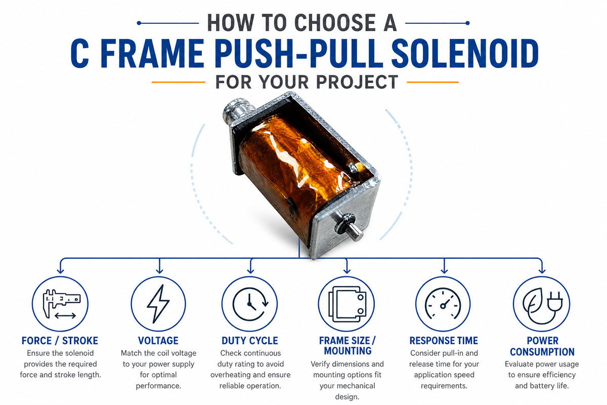
When choosing the right C Frame Push-Pull Solenoid, one should take into account not only the voltage but also the mechanical requirements first of all. Firstly, it is necessary to specify the type of the action: push, pull, release, lock, or position. Then measure the working stroke and determine the force needed at the beginning and the end of the stroke. The solenoid force depends on the plunger position, and the force value near the seated position should not be used as an example of the entire stroke.

Then one should determine the available power supply, including the rated voltage, the allowable current, the coil resistance, and the driving capacity. It is necessary to determine whether the solenoid will operate continuously or intermittently. The duty cycle is an important parameter because the temperature of the coil rises when it is energized. The device designed for short pulses may be overheated if it is left on continuously. One should also consider the ambient temperature, ventilation, other heat sources, and the allowed temperature of the finished product.

It is necessary to carefully consider the mechanical envelope, including body size, plunger diameter, the direction of the shaft, mounting holes, lead wire exit, connector position, return spring, and moving part clearance. One should avoid side loads, as misalignment increases friction, noise, wear, and the potential of sticking.

It is also necessary to evaluate the performance requirements, including the response time, operating noise, holding force, return force, cycle life, operating frequency, etc. In the case of smart appliances, the sound of impact is as important as electromagnetic force, and rubber stops or mechanical damping can be needed.

Finally, one should discuss the customization with the supplier, including drawings, voltage, stroke, force and position requirements, duty cycle, operating sequence, environment, annual quantity, and target life. Prototype testing should be done on the actual mechanism before the final design is confirmed. The validation should be done with the worst-case voltage, temperature, load, tolerance, and repeated cycling.

If the mechanism has to be energized for long periods, the continuous duty options should be compared. If the movement is the only purpose, then the pulse operation can reduce the heating and the power consumption as well as the coil size without changing the actuation force.

How to Prevent Typical Errors During Designing a C-Frame Push-Pull Solenoid?

1. Don’t choose the solenoid on rated voltage alone.

The voltage is just one parameter. Stroke, force, duty cycle, temperature, current, mounting space, return spring, and operating life are also important.

2. Don’t treat the holding force as the necessary initial force.

Solenoids provide maximum force near the seated position of the plunger. The force at the maximum stroke can be much lower.

3. Keep the stroke to a minimum.

An increasing air gap decreases the electromagnetic force. Make the required stroke as short as possible.

4. Determine the actual duty cycle.

A coil designed for short duty may become too hot if it is energized for too long.

5. Take into consideration the tolerance of the supply voltage.

Test the actuator at minimum and maximum voltage, including the voltage drop through wiring and the driver circuit.

6. Don’t side-load the plunger.

The shaft should be in its intended axis. Side loading causes friction, noise, wear, and sticking.

7. Don’t use the return spring, which is too strong.

The solenoid must overcome the spring force and external mechanical load.

8. Provide sufficient mechanical clearance.

Consider the manufacturing tolerances, thermal expansion, assembly variations, and wear.

9. Provide coil protection in the driver circuit.

When the inductive load is switched off, it generates a voltage transient. Include appropriate flyback or transient suppression.

10. Think about the operating noise.

High-speed plunger impact may produce clicks. The quiet appliance may need mechanical stops, damping material, reduced impact velocity, or controlled current.

11. Shield open-frame design from contamination.

The plunger movement can be blocked by dust, moisture, grease, fibers, and other foreign particles.

12. Look inside the finished product.

The bench performance doesn’t always mean the final performance. Test the actual assembly with the real voltage, temperature, load, tolerance, and expected cycle life.

Get A Free Quote Now

Contact Form

Related Products

Related News

Scroll to Top

Get A Free Quote Now !

Contact Form
If you have any questions, please do not hesitate to contact us.
Weilong Solenoid Company Culture