Mini Solenoid Lock Benefits
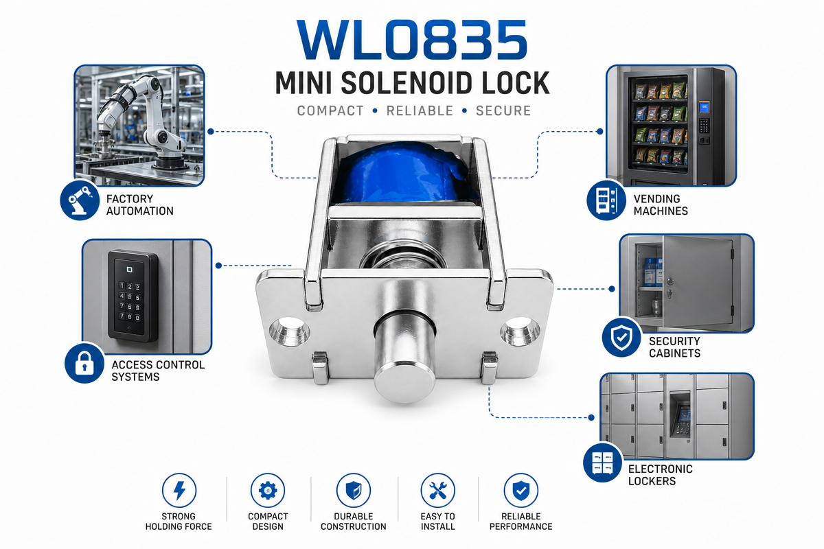
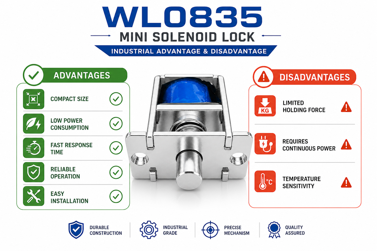
Mini Solenoid Locks come with many benefits for industrial applications. Small size allows them to fit in tight spaces. Automatic operation and low power consumption are ideal features especially for smart devices and automation applications. Their stable electromagnets, long-term use, and low maintenance.
Easily integrated to electronic control systems, sensors, and microcontrollers. Different voltages, stroke lengths and holding forces allow it to be used in many industrial applications. Personalization including waterproof design and mounting structures provide a versatile locking solution.
Mini Solenoid Lock Drawbacks
Some mini Solenoid Locks have tendency to heat up after long time usage if the duty cycle is not maintained. Holding force is normally smaller compared to other industrial Electromagnetic locks. Improper selection of voltage can affect performance and even destroy coils. Most models work properly when DC supply is stable. Without proper water-proofing, Mini Solenoid Locks may not last in rough outdoor conditions. To ensure proper functioning and longevity, Mini Solenoid Lock should be installed correctly.
Mini Solenoid Lock Troubleshooting Guide
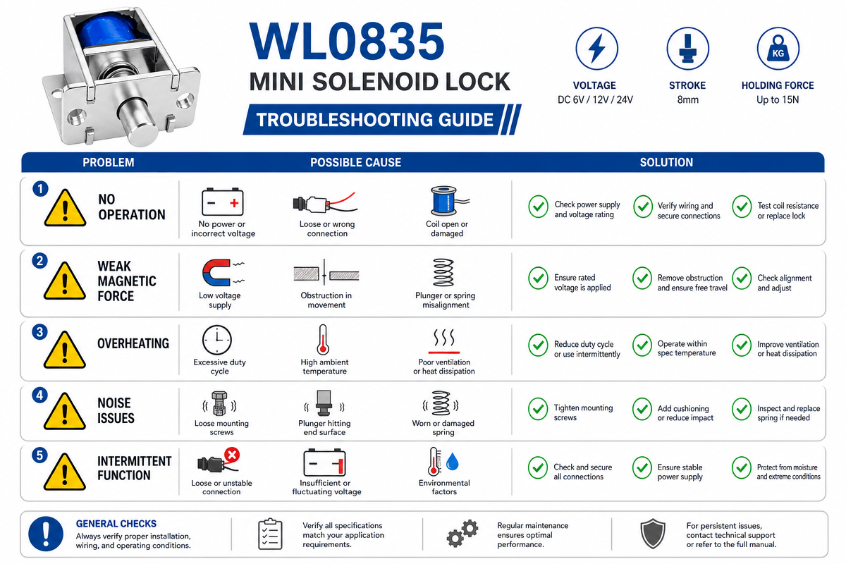
Symptom 1: The lock is not working (no click, no action of the bolt).
Potential Causes and Solutions
Power Supply Failure (the Most Frequent Case)
Test Method: Measure voltage using a multimeter at the connection pins of the solenoid lock.
Requirement: Mini solenoid locks usually require DC 12V. Voltage drop must not exceed DC 9V-11V upon lock operation.
Possible Reasons:
Inadequate current. Solenoid locks feature relatively high starting currents (in the range from 1A to 1.5A). Therefore, insufficient capacity of the access control power supply (less than 1A) results in excessive current draw.
Voltage Drop. Long distance between the lock and power supply (greater than 5 m), small wire gauge (< 1.0 mm2)
Corrective Action: Use special 12V 3A-5A power supplies for mini solenoid locks. Minimize the distance between the lock and the power supply or increase the thickness of power wire (22 AWG).
Cable Connection Error
Description: The solenoid lock is powered constantly. This happens when the lock is connected to NC (normally closed) output of the relay.
Suggested Action: connect controller’s output to NO (normally open) and COM terminals of the relay.
Lock Coil Malfunction.
Signs: No sound emitted, no magnetic field detected, proper cable connection and voltage.
Testing Method: measure coil resistance using a multimeter (ohm meter function).
Normal readings : Coil resistance should be in the range 10 Ω to 60 Ω depending on lock model.
Interpretation: Infinite coil resistance (open circuit) = broken coil. 0 Ω (coil short circuit) = the coil burned out; replace lock assembly.
Symptom 2: The lock emits sound/vibrations, but the bolt is not extending /retracting
Potential causes & solutions:
Locked Mechanism
Signs: The lock makes a “click” sound (lock coil activates), but the bolt does not extend or extends but won’t retract back.
Reasons:
Side Pressure: sagging of the door, misalignment of its opening; the lock bolt is pressing against edges of the striker/plate.
Dirt/Dust/Rusty Parts: accumulation of dirt, rust, or old grease inside the lock mechanism.
Suggested Actions: Release the side pressure by pushing/pulling the door gently, trying to establish a free movement of the bolt. Lubricate the internal components of the lock with WD-40 or silicone-based oil.
Incorrect Mounting
Signs: Weak holding force, buzzing.
Possible reasons: improper alignment of the solenoid lock and armature plate.
Suggestion: Make sure the lock assembly is mounted perfectly aligned and touching the surface of the armature plate. Excessive tightening of the mounting screws leads to insufficient surface contacts (just one line or point).
Symptom 3: LED indicator is defective
Troubleshooting
LED flickers/does not glow: Voltage drop is likely (typical issue with old 12V batteries).
Red LED glows continuously (on the magnetic locks with feedback): probably, the reed switch (position sensor) is bad. The lock still operates mechanically, however, fails to provide feedback signals.
Recommended troubleshooting sequence for Mini Solenoid Lock problems
Visual Inspection: check for visible obstacles to the operation of lock.
Manual Check: attempt to move lock bolt manually, can you feel any obstruction?
Measurement: Using multimeter: Voltage must be 11V minimum when lock turns on.
Polarity Test: connect lock directly to a brand-new 12V battery.
The lock doesn’t work: check wiring and controller.
Doesn’t work: the lock assembly is faulty.
Important: Mini solenoid locks are designed for intermittent duty only. They must not stay locked continuously longer than several seconds (e.g., 5-10 seconds maximum). In case the bolt is stuck and power remains applied, lock will burn out due to overheating. Pulse testing must be applied in all cases.
Maintenance Tips for Mini Solenoid Locks
Tip #1: Regular voltage checks
Make sure the voltage supplied to the lock is consistent with the voltage rating of Mini Solenoid Locks (12V/24V).
Tip #2: Inspect internal lock mechanisms.
Accumulation of dust and metal parts affects plunger movement.
Tip #3: Do not operate the lock continuously.
Mini Solenoid Locks are not suitable for continuous duty cycle applications.
Tip #4: Check the wiring.
Loose connection terminals lead to improper functioning of the lock.
Tip #5: Lubrication of moving components.
Apply industrial lubricants to speed up the operation of the lock.
Tip #6: Protect the lock from moisture.
Use waterproof models for wet environments to prevent electrical failure.