

Chapter 1 : Overview of Push-Pull Tubular Solenoid
The Push-pull Tubular Solenoid is a miniature electromagnetic actuator that creates linear motion using magnetic forces. This actuator converts electrical energy into mechanical motion (Push or pull). It is very useful in industrial automation, cars, medical apparatus, home appliances, vending machines, and security systems.
Since it comes in a cylindrical design, tubular solenoids feature better magnetic efficiency, increased force, rapid response, and increased longevity compared to regular solenoids. Due to its compact design, a tubular solenoid can operate in limited spaces.
The Push-Pull Tubular Solenoids are among the most sought after actuators currently due to their applications in robotic actuators, locking doors, fuel injectors, valves, transmissions, high precision machinery, and others.
Chapter 2 : Push-pull tubular solenoid working Principle
A push-pull tubular solenoid operates based on electromagnetic theory. Whenever there is current flow through a conductor, a magnetic field is formed around the conductor. Wrapping the conductor into coils helps concentrate the magnetic field created by the current flow in the conductor. In a push-pull tubular solenoid, the coil of conductor is usually wrapped around a ferromagnetic core. When current flows through the coil of conductor, a strong magnetic field is formed, which acts on a plunger within the coil-core assembly. The plunger in the push-pull tubular solenoid is usually made up of a magnetic material.
Once current starts flowing through the coil, the resulting magnetic field either attracts or repels the plunger in its action. The movement of the plunger can then be used to achieve mechanical actions including opening, closing or holding an object. The mechanical force created by the tubular solenoid can be used in various operations. They range from simple applications such as doorbells to more complex uses, like in industrial machines.
It should also be noted that the mechanical force developed by the plunger in the tubular solenoid is directly related to the magnitude of the current flowing through the coil. Therefore, controlling the current through the coil makes it possible to regulate the movement of the solenoid’s plunger, making the tubular solenoids ideal for precision applications. The push-pull tubular solenoid is usually of two types: the normally open or normally closed. In a normally open solenoid, the plunger moves back when the coil is energized. As a result, some form of fluid is allowed to move through the push-pull tubular solenoid.
Chapter 3 : Push Pull Tubular Solenoid Structure
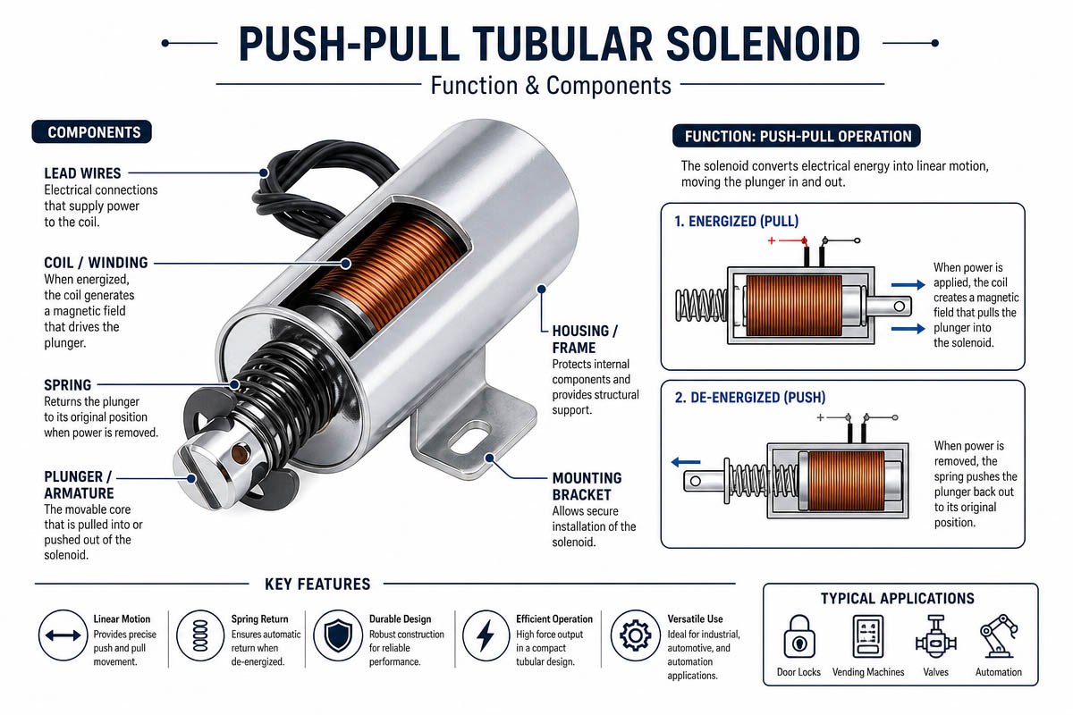
There are several components that make up a tubular push-pull solenoid including:
3.1 Copper Wire Coil
Wire Coils
These are made of insulated copper wire wound in the form of a bobbin. Copper is a good conductor of electricity, besides producing powerful magnetic fields.
Insulation Materials
The coil windings are coated with insulation materials to prevent electric short-circuit and guarantee longevity.
Purpose
Energize the coil to generate the electromagnetic field.
3.2 Core Material
They consist of iron or carbon steel with magnetic permeability.
Objective
The core directs and concentrates the magnetic flux of the coil to provide efficiency.
Form
Being cylindrical, it distributes the magnetic field optimally while enhancing the motion of the plunger.
3.3 Plunger
Materials
The plunger can be made from steel or iron alloys.
Properties
It moves in a straight direction through electromagnetic force to perform mechanical work.
Movements of the Plunger
Pulling type Motion
Pushing Movement
Bidirectional Movement (Push-pull type)
4.4 Spring Return
Most push-pull tubular solenoids include a spring return that returns the plunger automatically.
Advantages
Automatic reset
Fast plunger action
Definite Position
3.5 Housing Enclosure
The outside casing protects the internal components against:
Dust
Moisture
Physical damage
Metal enclosures increase magnetic efficiency, besides offering durability.
3.6 Working Principles
Step 1: Activating the Solenoid
Electrical current passes through the copper coil.
Step 2: Generation of the Magnetic Field
When energized, the coil produces a concentrated electromagnetic field.
Step 3: Movement of Plunger
Electromagnetic force pulls or pushes the plunger.
Step 4 Mechanical Operation
The motion activates locks, valves, switches, or other mechanical parts.
Step 5: Return of the Plunger
When de-energized, the plunger is pulled back to its resting position.
Chapter 4: Types of Push-pull Tubular Solenoid
There exist different types of tubular solenoids depending on applications.
4.1 Tubular Solenoid(Pull Type)
Upon activation, the plunger moves towards the center.
Applications
Door locks
Safety Latches
Medical Instruments
4.2. Push-Type Tubular Solenoid
When energized, the plunger moves outwardly.
Application Areas
Vacuum ejectors
Drug dispensers
Mechanical triggers
4.3 Push-Pull Tubular Solenoid
Depending on configuration, push or pull motion is generated.
Areas of Usage
Automation industry
Robotics.
Precision control systems
4.4 Tubular Solenoid – Holding Type
It features a high holding power for low electricity consumption.
Application
Electromagnetic lock
Valve retaining systems
4.5 Latching Type Tubular Solenoid
Permanent magnets retain their positions without electrical energy.
Application areas
Systems that conserve energy
Battery operated appliances
Chapter 5 : Advantages and Disadvantages of Push-pull Solenoid
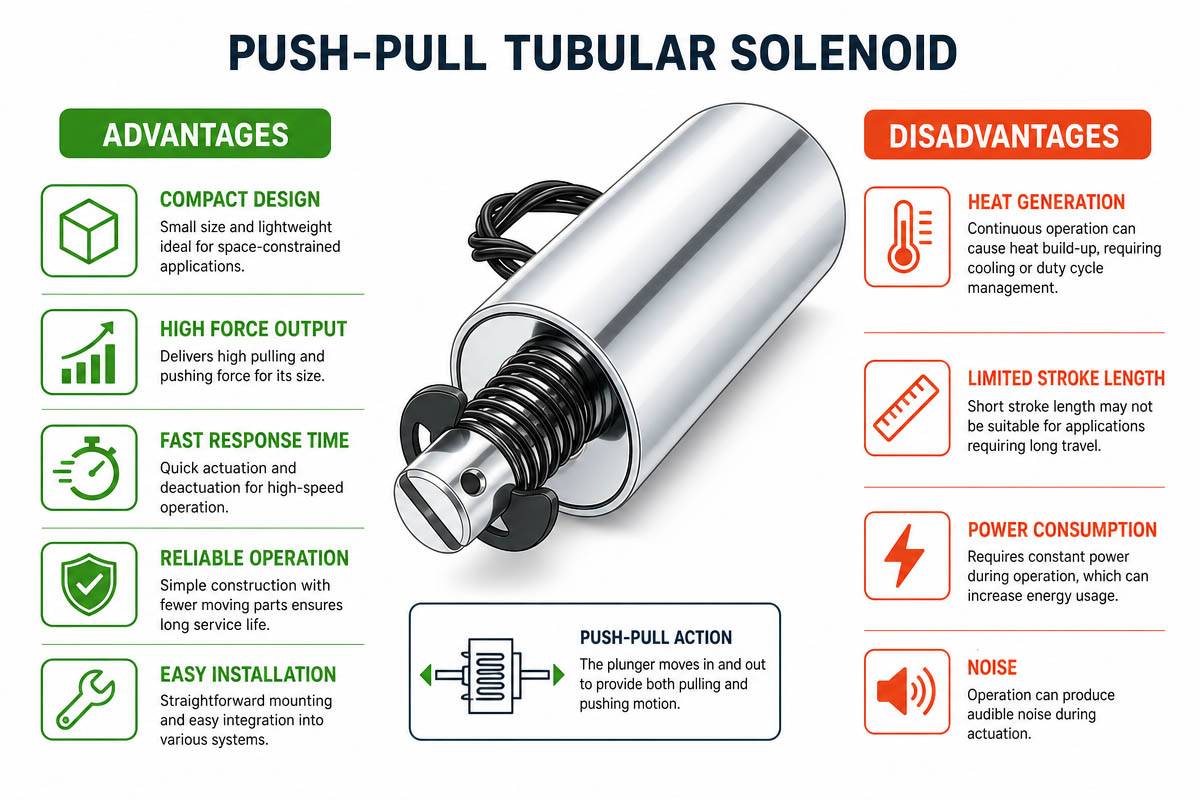
5.1 Advantages of Push-pull Solenoid
High Force Output
Due to compact nature, tubular solenoids deliver high output force
Small Size
Thanks to their cylindrical shape, these solenoids save installation space.
High-Speed Response
Rapid reaction improves automation process
Long Lifespan
Increases longevity with simpler construction
High Reliability
Reliable even in repeated actions.
Easy to install
Can be easily incorporated into automated machines.
5.2 Disadvantages of Push-pull Solenoid
Linear movement range is relatively low in tubular solenoids.
Production of Heat
Heat due to continuous operation
Susceptible to external magnetic interference
Other magnetic fields interfere with performance
Requires Electrical Energy
Power consumption requires thermal management.
Chapter 6 : Selecting a Suitable push-pull Tubular Solenoid
Choosing the right solenoid will depend on the application.
6.1 Determine Required Force
Calculate:
Pulling force
Outward pulling force
Weight of load
Drag
Always consider some margin of safety.
6.2. Stroke Length Measurement
Depends on the amount of linear motion
Required Stroke influences:
Soloid Size
Wiring arrangement
Power requirement
6.3 Power and Voltage
Standard Voltages
DC 6V DC 12V DC 24V
DC 48V
Wrong voltage causes:
Magnetic inefficiency
Coil destruction
Heating up
6.4 Duty Cycle Evaluation
The operating cycle is the proportion of the operating time.
Test:_____________
Duty Cycle 10%
25% duty cycle
Continuous Duty (100%)
Requires effective heat dissipation
6.5 Environment
Environmental Conditions Considered Include:
Operating temperature
Amount of moisture
Exposure to dust
Waterproofing requirements
Resistance to corrosion
6.6 Installation Area
Mounting Area should be:
Length
Outer diameter
Holes for fixing
Connecting terminals location
Chapter 7: how to avoid comment mistake while Selecting a push-pull Tubular Solenoid
Incorrect selection leads to reduced life expectancy or even failure.
7.1 Duty cycle Error
Continuous energization of intermittent duty solenoid will cause overheating.
7.2 Failure to estimate Force
Inadequate strength for full operation.
7.3 Incorrect stroke length
Inadequate stroke length to activate completely.
7.4 Ignoring Temperature rise
Increased ambient temperatures decrease coil resistance
7.5 Wrong voltage Selection
Excessive voltage damages coil while inadequate voltage produces insufficient power.
7.6 Neglecting Protection
When working in an environment requiring protection from moisture, dust and other forms of contamination.
Chapter 8: Push-pull Tubular Solenoid Power Consumption Calculation
Power Formula:
P= V * I P = VI Where:
P = Power (watts)
V = Voltage (volts)
I = Amperes(current)
Example
Given
Voltage 12 V Current 0.5 A
Then, P = 12 * 0.5 = 6 W
Factors that affect Actual Power Requirement Include:
Resistance of coils
Duty cycle
Temperature increase
Chapter 9: Push-pull Tubular Solenoid Applications
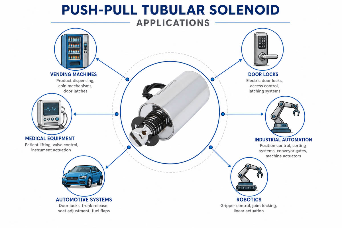
Push-Pull Tubular Solenoids are commonly used in many areas.
9.1 Industry 4.0 Automation
Includes :
Conveyor Systems
Sorting Machines
Robotic grippers
Packaging machinery
9.2 Automotive Industry
Usage Includes:
Fuel Injection Systems
Transmissions shifters
Door Locking Systems
Accelerators
9.3 Medical Apparatus
Application Areas :
Medical Diagnosis Equipment
Drug dispensing system
Laboratory automation
9.4 Home Appliances (Electrodomésticos)
Usage Includes:
Clothes washing machines
Dish washing
Coffee machine
Intelligent locks
9.5 Security Systems Security Systems
Application Areas:
Electronic door locks.
Access control devices
Safe locking mechanisms
Chapter 10 – Troubleshooting Guide for Push-pull Tubular Solenoid
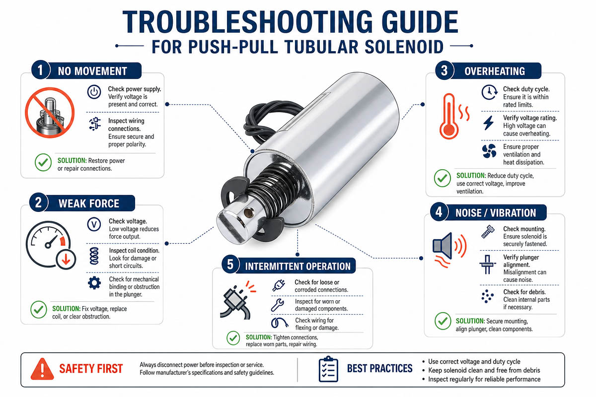
Issue 1: No Movement
Possible reasons
Absence of power
Broken spring
Wire Problem
Blocked plunger
Repair methods
Voltage test
Connectivity of wires,
Test Coil Resistance
Remove dirt from plunger assembly
Issue 2: Insufficient power Output
Possible Cause
Low Voltage
Air Gap is very big
Getting hot too fast
Wrong Duty Cycle Fix
Check voltage source
Reduce Stroke Length
Improve Cooling
Use appropriate duty
Issue 3 : Overheating Problem Possible Cause
Continuous energization
Overcurrent
Poor ventilation solution
Reduce Duty Cycle
Cooling device Addition
Purchase continuous duty Solenoid
Problem 4. Slow Response time
Possible causes:
Mechanical friction
Weakened spring Solution
Lubricate moving Parts
Choose alternative Spring
Reduce voltage
Chapter 11: Frequently Asked Questions about Push-Pull Tubular Solenoid
1. What is the difference between a Push & Pull tubular solenoid?
The difference is in the direction of the force applied to the shaft.
Pull Solenoid Plunger (shaft) is pulled into the coil housing when energized. This is a typical design where the output force is generated by the movement of the armature towards the center.
Push Solenoid: When energized, the plunger extends out of the housing. This is accomplished by fixing a non-magnetic rod to the armature. The rod extends from the closed end of the tube to push an object .
2. How do I choose between Push or Pull type for my system?
For a system that needs to remain in a retracted state and extend only upon applying voltage, you need a Push Solenoid. If you need to pull something towards you or operate a latch at a distance, you need a Pull Solenoid. Pull solenoids are usually the majority of the market share because they are mechanically simpler than push solenoids.
3. What is “Duty Cycle” and why does it matter?
Duty cycle refers to the percentage of ‘on time’ compared to the entire cycle (On/(On+Off) x 100%). It determines the maximum duration the solenoid can work without overheating.
Continuous Duty (100%): Continuous running capacity without downtime (used in locks, holding mechanisms).
Intermittent Duty (e.g. 25%, 50%) : Greater force capacity, but it can be powered only for brief moments (milliseconds or seconds) before taking a cooling rest.
4. What could cause a push-pull tubular solenoid to fail to actuate?
Manufacturing statistics indicate that the most common causes are:
Poor wiring Loose connections or rusty terminals will disrupt the current flow.
Burnt coil: Usually due to exceeding the rated duty cycle or voltage, causing degradation of insulation.
Loose iron core vibration: Loosened vibration of the iron core will weaken the magnetic field.
Residual Magnetism: (if the plunger is in direct contact with the metal base, without a spacer) the residual magnetism will keep the plunger locked after disconnecting the power source.
5. Will the push-pull tubular solenoids be equipped with a return spring?
No. There is no return spring installed in the regular tubular solenoids. Single action (single direction) is designed for the mechanism. Without the power source, the plunger will revert to its starting position using external force such as gravity/load.
6. What kind of stroke do I require?
Tubular solenoids are meant to be used for longer strokes than the regular C-frame solenoids, but you should design the system to require the smallest stroke feasible.
Short Stroke: 0-3 mm (ideal for maximum holding power).
Intermediate/Long Stroke: up to 15 mm or more, but reduced magnetic field strength with increased stroke length.
7. Can I get the plunger or shaft customized to fit my requirements?
It is not recommended to alter the plungers manually. The plungers are normally precisely machined and chrome-plated for smoother operation and anti-corrosion protection. Cutting or grinding them may lead to damage to the plating and blockage of the passage. Many manufacturers offer customized designs (specialized stroke length, diameter, and materials).
8. What is the service life of the Push-pull tubular solenoid?
Service life is highly dependent on load, stroke length and environment, however, there are general guidelines:
Standard Service Life: approx. 100k cycles .
Extended Service Life: approx. 2-3 hundred thousand cycles (requires special design configuration).
Degradation Factors: Sideways loads (pulling at angles) will significantly reduce the life span of the plunger since the plunger is supposed to move freely and minimize friction .
Chapter 11: CONCLUSION:
Push-pull tubular solenoid is small, durable and energy-efficient electromagnetic actuators that are extensively utilized in manufacturing, vehicle, healthcare and domestic appliances industries.
High-speed response, powerful output force and easy installation make them the best options for linear motion control systems. Nonetheless, proper selection based on force, stroke, duty cycle and environment is crucial for their long-term performance.
Knowing the working principles, construction, pros, cons and troubleshooting techniques will help designers and purchasers choose the appropriate tubular solenoid for their applications.

