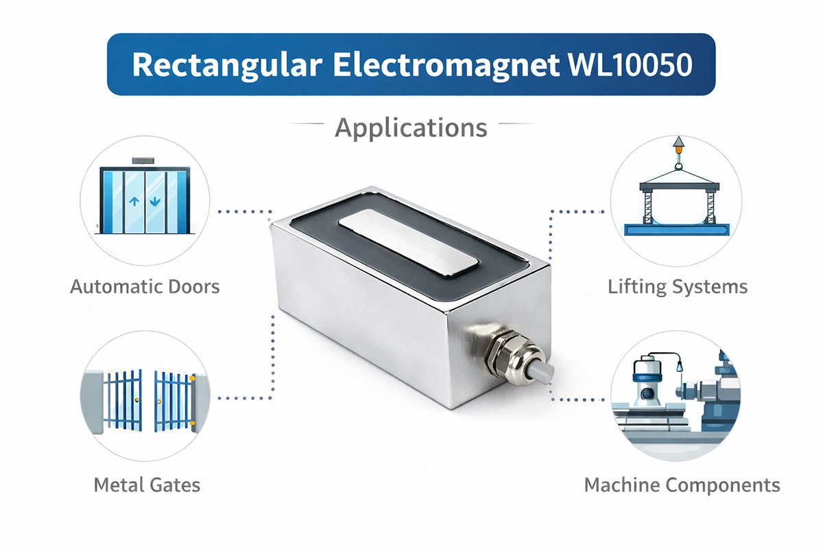
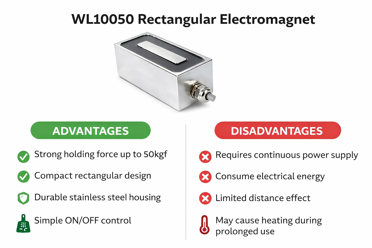
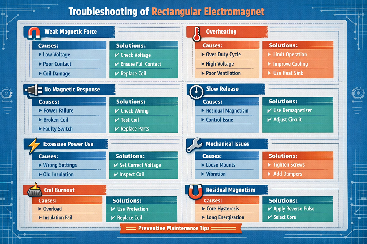

| Model | Size | Install Thread | Power | Install | Min thickness of contact plate | Working Duty |
| WL-302020 | 30*20*20 | 40N | 2.4W | 2*M4_L10 | 2mm | 100% |
| WL -402020 | 40*20*20 | 100N | 3W | 2*M4_L18 | 3mm | 100% |
| WL -502520 | 50*25*20 | 250N | 3.5W | 2*M5_L25 | 4mm | 100% |
| WL -502525 | 50*25*25 | 300N | 4W | 2*M5_L25 | 4mm | 100% |
| WL -603025 | 60*30*25 | 400N | 5W | 2*M6_L30 | 5mm | 100% |
| WL -603030 | 60*30*30 | 400N | 5W | 2*M8_L30 | 5mm | 100% |
| WL -703530 | 70*35*30 | 800N | 7.5W | 2*M8_L35 | 6mm | 100% |
| WL -804030 | 80*40*30 | 900N | 10W | 2*M8_L40 | 6mm | 100% |
| WL -904030 | 90*40*30 | 1000N | 10W | 2*M8_L45 | 6mm | 100% |
| WL -1003530 | 100*35*30 | 1000N | 9.5W | 2*M6_L50 | 6mm | 100% |
| WL -1005040 | 100*50*40 | 1200N | 14W | 2*M8_L50 | 10mm | 100% |
| WL -1204030 | 120*40*30 | 1500N | 11W | 2*M8_L50 | 10mm | 100% |
| WL-1205040 | 120*50*40 | 2000N | 16.8W | 2*M8_L70 | 10mm | 100% |
| WL-1206050 | 120*60*50 | 2400N | 14W | 2*M8_L70 | 10mm | 100% |
| WL-1505050 | 150*50*50 | 3000N | 18W | 2*M10_L80 | 10mm | 100% |
| WL-1506050 | 150*60*50 | 3500N | 36W | 2*M10_L80 | 10mm | 100% |
| WL-2008060 | 200*80*60 | 8000N | 60W | 2*M12_L100 | 10mm | 100% |
Choosing Rectangular Electromagnets: What to Consider?
Choosing a rectangular electromagnet is a process that requires attention to a set of parameters reflecting the mechanical, electrical, and environmental characteristics of your electromagnet application. Here is a step-by-step guideline covering 500 words of essential considerations.
1. Define Safety Factor and Holding Force
To begin with, it is necessary to identify the required holding force specified in Newtons (kilograms). It is determined based on the weight of the load and the maximum air gap between the magnet and armature (plate made of steel). The higher the gap, the lower the holding force, with even a 1 mm gap potentially reducing the force by 80 percent and more.
What to do: Identify the largest possible air gap. As a result, to compensate for surface contamination, fluctuating voltage, and temperature increases, select an electromagnet capable of producing at least 2–4 times more force at the defined gap.
2. Ensure that the Size and Shape Will Match Your Mounting Space
Rectangular electromagnets can be installed into areas where round magnets won’t fit, such as along the rail, in a channel, or under a flat plate. Both the footprint area (height x width) and height cannot interfere with nearby objects.
Tips: Generally, larger pole faces provide higher holding force. Still, in case of insufficient mounting space, a higher electromagnet (more coil turns) will compensate with enhanced magnetic flux.
3. Required Power and Voltage (AC/DC)
Industrial rectangular electromagnets typically operate with a direct current of 6, 12, 24, or 48 volts (DC). Electromagnets running on AC power are available. However, due to humming noises and loss of holding force at zero crossing, AC electromagnets are less suitable for lifting applications.
Main characteristics:
Power (W): the higher the power, the stronger the magnetic field generated, but also the more heat produced.
Duty cycle: intermittent (e.g., 25%) or continuous (100%). An intermittent-duty electromagnet operated continuously will overheat.
Steps to take: Identify the current requirement (P=V*I) and ensure your power supply can deliver sufficient current permanently.
4. Environmental Temperature and Protection
Electromagnets can get pretty warm. With a continuously operating unit, temperatures can reach 80-100°C. If the surrounding temperature is higher, reduce force or purchase an electromagnet with built-in thermal overload protection.
Environmental protection
IP00 (open-frame) – dry interior environment.
IP65/67 (encapsulated) – designed for outdoor usage, washing, and dusty environments.
Material: mild steel (standard), stainless steel (resistance to rusting but weaker holding force), or aluminum (lightweight).
5. Electromagnetic Control Interface
Will it be necessary to change electromagnetic states?
Direct control—apply a relay or MOSFET switch capable of managing inrush current (typically 3 to 5 times higher than steady-state current).
Control with PLC or microcontroller – to eliminate voltage spikes, install a flyback diode connected to the coil.
Remote release – consider purchasing electropermanent magnets that can maintain permanent holding without power and release after sending a short pulse.
6. Installation and Mechanical Integration
Threaded mounting holes (M3-M8) may appear on the back or side of rectangular electromagnets. Have a look at the following mounting options:
Through-holes mounting – screw from front to lock in position.
Counterbore hole mounting—flat mounting.
Stud-type – mounting using bolts or welding.
7. Pre-Integration Testing
To determine whether the required holding force will be maintained, order and perform testing of the electromagnet with actual armature at the worst-case scenario air gap. Use a pull gauge for measuring the force and checking whether the electromagnet is overheating within 30 minutes of continuous operation.
Conclusion
Force needed at worst-case air gap times safety factor
Rectangular electromagnet dimensions
Required voltage (e.g., 24 VDC)
Continuous or intermittent-duty operation
IP environmental protection
Pattern of mounting holes
Protective measures against spikes in current (flyback diode)
In case of careful examination of seven aspects described above, the choice of a rectangular electromagnet will prove to be safe, efficient, and affordable.