Ferrite Coil Inductor Guide for Efficient Power
Best Ferrite Coil Inductor for Power Electronics
Buy Ferrite Coil Inductor for Industrial Use Today
Ferrite Coil Inductor Design For Modern Devices
Ferrite Coil Inductors for Automation Equipment
Ferrite Coil Inductors for Industrial Electronics
Ferrite Coil Inductor Guide for Efficient Power
Best Ferrite Coil Inductor for Power Electronics
Buy Ferrite Coil Inductor for Industrial Use Today
Ferrite Coil Inductor Design For Modern Devices
Ferrite Coil Inductors for Automation Equipment
Ferrite Coil Inductors for Industrial Electronics

WL0710 Ferrite Coil Inductor Design Tips for Engineers

Ferrite coil inductor is a passive component consisting of copper wire winding around ferrite core. It helps to accumulate energy in a magnetic field and control current flow in the circuit. Thanks to its high magnetic permeability and low energy loss, ferrite material allows to increase efficiency of such inductors at high frequencies. These components are widely used in power electronics, transformers, and EMI filters. Ferrite coil inductors are necessary to control voltage and decrease noise level. Because of their high performance at high frequencies, such inductors are widely used in modern electronic devices including communication devices, automotive electronics, industrial control systems and switching power supplies.

Ferrite Coil Inductor Product Overview

Ferrite coil inductor is an efficient electronic component, which is used for energy accumulation, filtering and EMI suppression. It consists of copper winding around the ferrite magnetic core, which allows to increase inductance value and reduce energy losses at high frequencies. Such inductors are widely used in power supplies, telecommunication devices, automotive electronics and industrial control systems. They ensure stable current regulation and efficient performance of circuits with low levels of electrical noise. Ferrite inductors are available in different geometries and sizes and are necessary for compact circuits of modern electronic devices.

Compact Ferrite Coil Inductor Product Video

Compact Ferrite Coil Inductor Detail Display

Compact Ferrite Coil Inductor Technical Datasheet

Item Description
Ferrite Coil Inductor Enameled copper wire
Wire Diameter 0.8(AWG options available)
Winding Type Single-layer round or sectional  winding
Core Material  Magnetic Rod
Footprint length 8 mm
Encapsulation Optional varnish, epoxy, or coating
Mounting Through-foot / Custom

Electrical Specifications (Typical)

Parameter Description
Inductance Range 0.1 µH – 100 µH (customizable)
Inductance Tolerance ±2%, ±5%, ±10%
DC Resistance (DCR) Custom
Q Factor High Q, optimized for frequency range
Self-Resonant Frequency High, application-dependent
Operating Frequency kHz to MHz range
Rated Current Custom per design
Insulation Resistance ≥100 MΩ

HOW FERRITE COIL INDUCTOR WORKS

Ferrite coil inductor is a component transforming electrical energy into magnetic one due to the process of winding copper wire around the ferrite core and applying current flow. Magnetic field is created and increased due to the presence of ferrite core, having a high magnetic permeability. Due to the change in current flow, the inductor creates an opposite voltage according to Lenz’s law.

This feature helps the ferrite coil inductor to prevent any changes in the current.

At high frequencies, ferrite material is useful to reduce eddy current losses. It makes ferrite inductors effective for noise suppression and current smoothing in a circuit.

MAIN FEATURES OF FERRITE COIL INDUCTOR

High magnetic permeability and low energy loss are typical for ferrite coil inductors, which are also compact and light-weight. Such inductors allow to achieve high inductance values and have good EMI suppression capabilities. The use of ferrite cores allows to reduce eddy current losses, increasing efficiency of switching circuits. They are durable enough to work in various temperatures. Such inductors are good for power electronics, telecommunication devices and industrial automation.

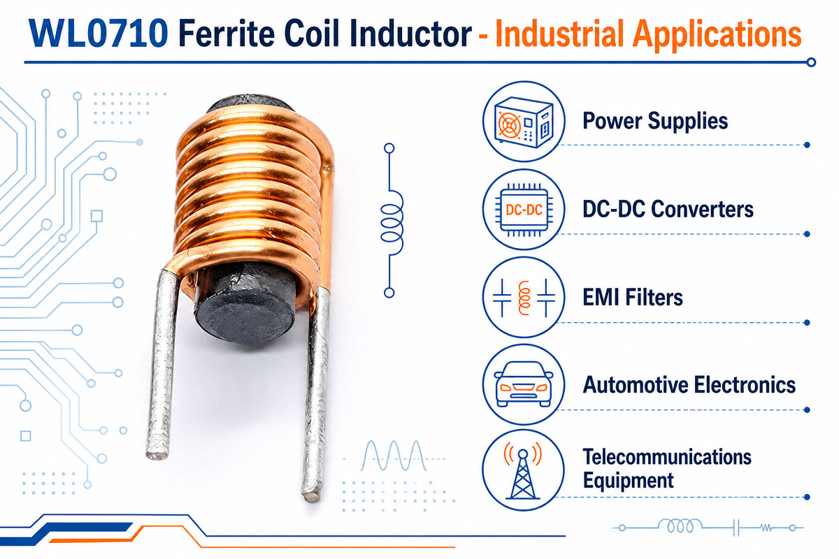
Ferrite Coil Inductor Industrial Application

Ferrite Coil Inductor Industril Applications

Ferrite coil inductors have wide range of applications due to their efficiency. In power electronics, ferrite inductors are important parts of switching power supplies and voltage regulation systems.

In telecommunication industry, they are used for signal filtering and EMI suppression to ensure the proper functioning.

Ferrite inductors are widely used in automotive systems such as engines control unit and infotainment systems, electric vehicle control systems and other automotive electronics. They allow to improve energy efficiency and reduce electromagnetic interference in automotive circuits.

In industrial automation, they are used for motor drives, PLCs, and control circuits. Moreover, inductors are necessary for renewable energy systems such as solar inverters and wind power conversion.

In consumer electronics including smartphones, laptops, LED lighting, and other devices, ferrite inductors are important for energy and noise control.

Ferrite Coil Inductor Advantage and Disadvantage

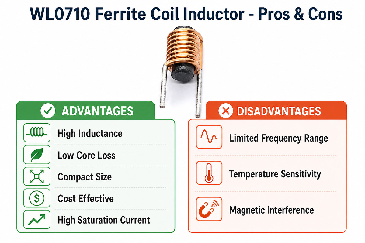
WL0710 Ferrite Coil Inductor Pros & Cons

Ferrite coil inductors provide high performance and many benefits for modern electronics. High efficiency at high frequencies allows to use such inductors in switching power supplies and telecommunication devices. Also, ferrite material helps to reduce energy losses and increase the magnetic performance. They are compact in size, which allows to use inductors in small electronic devices. Besides, good EMI suppression is provided by ferrite inductors.

However, they have some disadvantages. They could be saturated at high currents, which would cause inductance degradation. Also, they could have core losses at extremely high frequencies depending on the material grade. The mechanical fragility could be the problem for them in harsh conditions. Compared to air-core inductors, they could have non-linear behavior in some cases.

FERRITE COIL INDUCTOR TROUBLESHOOTING

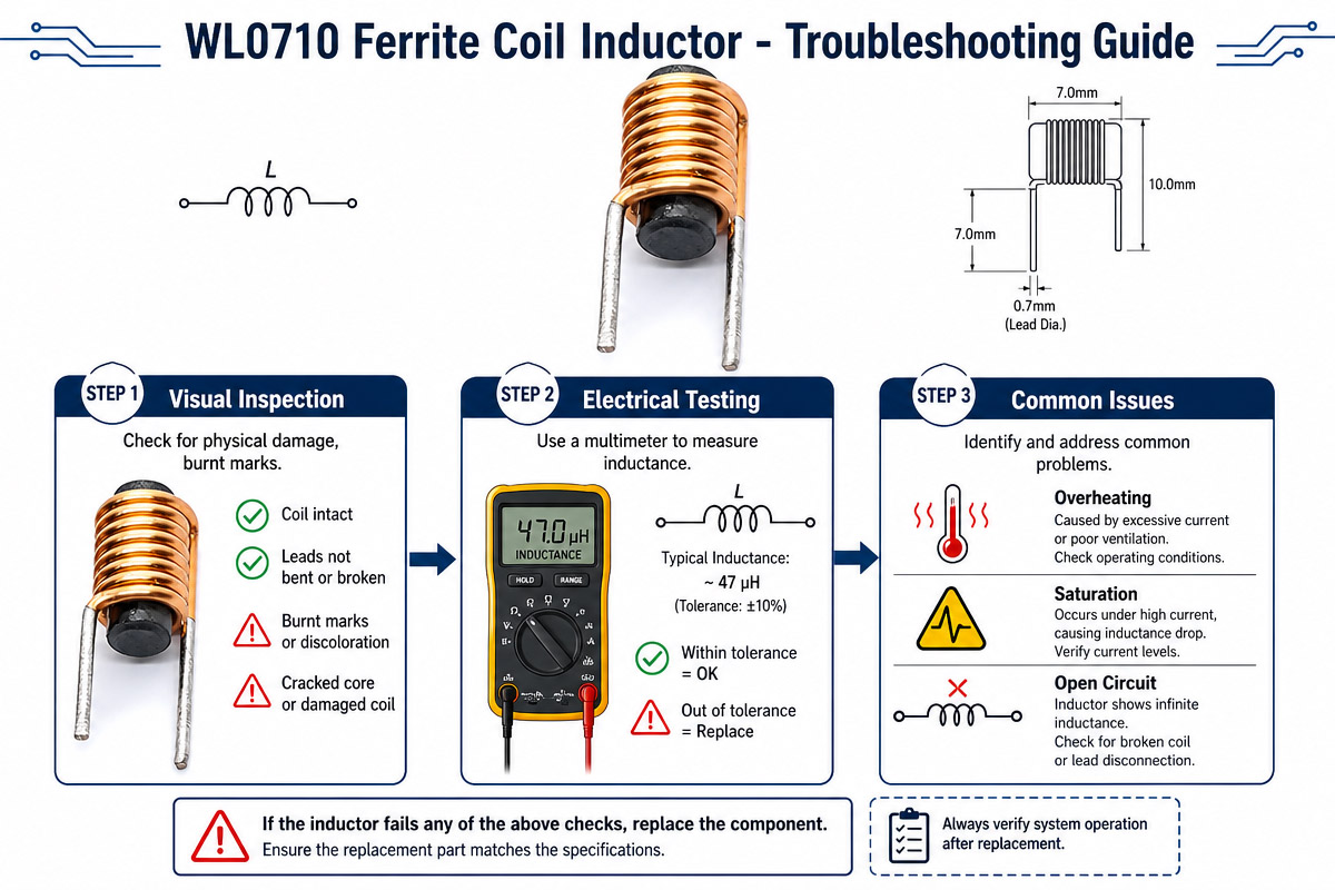
WL0710 Ferrite Coil Inductor Trouble shooting guide

There are several things which should be taken into account in case of failure or poor performance of ferrite coil inductor. The first one is checking whether the inductor is saturated due to high current load, which would cause sharp decrease of inductance. It could also cause overheating.

In case of noise problems, it is important to evaluate the EMI performance of the inductor. Improper shielding or positioning on the PCB could cause additional interference. In addition, inductance measurement should be performed since it could vary because of manufacture or damage.

Besides, it is important to check whether the ferrite inductor is mechanically damaged and there are some cracks in the core. In such case, the inductor should be replaced. Inappropriate frequency application could cause poor performance of inductor in case of high frequency.

Thermal imaging and LCR meter could help to troubleshoot inductor.

FAQs of Ferrite Coil Inductor

1. What is a ferrite coil inductor used for?

It is used for energy accumulation, filtering of signals, and electromagnetic interference reduction in power electronics and communication systems.

2. How does a ferrite coil inductor improve efficiency?

It improves efficiency by reducing energy losses at high frequencies and controlling current in switching circuits and power supplies.

It improves efficiency by reducing energy losses at high frequencies and controlling current in switching circuits and power supplies.

Ferrite material has high magnetic permeability and low eddy current losses, making it perfect for high-frequency and low-loss applications.

4. Where are ferrite coil inductors commonly applied?

They are widely used in SMPS, automotive electronics, telecommunication devices, industrial controllers and renewable energy systems.

5. What happens if an inductor saturates?

In case of saturation, the inductance sharply decreases, which causes overheating and instability of the circuit performance under high current load.

6. How to choose the proper ferrite coil inductor?

You should select it according to the inductance value, current rating, frequency range, DC resistance and thermal performance requirements of your circuit.

7. Are ferrite coil inductors suitable for high frequency?

Yes, they are designed specifically for high-frequency operation with low energy loss and good EMI suppression capability.

8. What are common failures in ferrite inductors?

The common failures include saturation of core, overheating, winding damage and cracks caused by mechanical stress.

How to selecte a Ferrite coil inductor

Selection of the proper ferrite coil inductor is very important for circuit performance. First of all, the value of inductance should be defined. In order to provide stable working of circuit, it is important to select an inductor with appropriate inductance value.

The next thing to consider is the maximum current that the inductor could handle. The saturation of inductor would cause significant reduction of its performance. Also, the core material is important because there are different ferrite materials for specific frequency range.

Frequency response is the next parameter to take into account, especially in case of high-frequency applications when it is necessary to use low core loss ferrite materials.

The temperature stability is also important especially for automotive and industrial electronics.

The size and packaging are important parameters in compact electronic devices. Small inductors should satisfy the electrical requirements of the circuit.

Also, low DC resistance is required for ferrite inductors to prevent energy losses and overheating.

In order to ensure proper functioning of the circuit, especially in case of sensitive communication or medical devices, it is important to pay attention to EMI performance. Shielded ferrite inductors could be used in noisy environment.

Moreover, cost is an important consideration but should not influence performance or reliability.

Working with trusted manufacturer allows to ensure consistent quality and stable supply.

Finally, the testing and prototyping are also important steps in the selection process. They help to ensure that selected inductor performs properly in real-life operating conditions.

TIPS FOR AVOID COMMON DESIGN MISTAKES

One of the common mistakes in ferrite coil inductor design is incorrect selection of inductance value, which causes unstable working of the circuit. Another mistake is lack of attention to the current saturation of the inductor, which would cause performance degradation under high loads.

Poor thermal design could cause overheating and malfunction of the inductor. The engineers also forget about EMI performance of inductors, which causes noise in finished product. Low quality ferrite material decreases efficiency and increases energy losses. The wrong winding could also influence the inductance value stability. The proper simulation, testing and material selection could help to avoid these mistakes.

How to Calculation of  a Ferrite Core Inductor Inductance

It seems to be the main point to consider during the designing of the power electronics – calculating the inductance of the ferrite core inductor. The point is to know all the parameters of the core and use a proper model for your application. The ferrite cores are considered to be a preferable choice in the high frequency applications due to their low core losses. There are many approaches that may be used for the estimation of inductance of ferrite core inductor.

Basic Approach: The Inductance Factor (A_L)
A typical approach and the easiest one is using inductance factor (or A_L value). This is the most typical approach especially for standard core shapes. A_L (which is usually expressed in nH/N²) is the core constant. It is an inductance of a single turn of a wire. It depends on the geometry of the core and its permeability.

The inductance (L) can be easily calculated using the next formula:

L = A L N 2

Where:

L is the inductance in nanohenries (nH).

A_L is the inductance factor of the core (nH/N2).

N is the number of turns of the winding .

It is a practical approach in order to make a first order design. The A_L value can be found by the manufacturer in the core datasheet and is usually measured at low signal level (e.g., 1 kHz, B < 10 gauss). The standard A_L values for many cores are defined by the international standard like IEC 62358.

If you have a core with A_L = 250 nH/N² and you wound 10 turns, then the inductance will be L = 250 nH * 10² = 2500 nH or 25 uH.

Calculation of Inductance Based on Principles of Magnetic Circuit
You may also calculate inductance according to the principles of the magnetic circuit. This approach is more flexible and can be used when you want to take into consideration some additional aspects such as air gaps.

Inductance is determined by:

L = N ^ 2 / \mathcal{R}_{total}

where $\mathcal{R}_{\text{total}}$ is the total reluctance of the magnetic circuit. Reluctance is the magnetic equivalent of electrical resistance and is calculated for each part of the magnetic circuit (the core and air gaps) using the next formula:

ℛ = l μ 0 μ r A

Location:

l is the average length of the magnetic path of the section.

μ 0 is the permeability of free space (4π × 10 −7 H/m).

μᵣ is the material’s relative permeability.

A is the cross-section area of section.

The total reluctance of a core with uniform cross-section and length is the sum of the reluctance of the core and the reluctance of the air gap. ℛtotal = ℛcore + ℛgap. This approach is useful . It shows how adding an air gap (with a low μᵣ = 1) increases the total reluctance and, therefore, decreases the inductance. This is a design approach that is used to prevent the core saturation under the influence of high DC bias currents.

Additional Considerations
These approaches give us a good start, but calculating the “true” inductance of the ferrite core inductor might be a bit complicated. The inductance is not constant. It changes depending on the operating conditions. Therefore, while making the design, you may take into account these aspects:

DC bias: The effective inductance reduces and the core is saturated more when the DC current flows through the winding. That is why it is preferable for the designers to use A_L value from the chart which considers the required LI^2 energy, rather than nominal un-biased value .

Frequency: The permeability of ferrite materials is frequency dependent. That is why inductance and core losses (ESR) should be taken into account as frequency-dependent for the high frequency applications.

Gap Modeling: The simple reluctance formula is less effective for the cores with big air gaps due to the presence of fringing flux. The more complex model is required for the accurate calculation of the air gap reluctance.

Conclusion
As it was mentioned above, the A_L approach, based on the formula L = A_L * N², is the fast and accepted way of determining inductance, but the more complex design may require the usage of the magnetic circuit approach or even frequency-dependent models.

Get A Free Quote Now

Contact Form

Related Products

Related News

Scroll to Top

Get A Free Quote Now !

Contact Form
If you have any questions, please do not hesitate to contact us.
Weilong Solenoid Company Culture
