Copper Flat Core Coil for Automotive Inverters Overview
opper Flat Core Coil for Power Supply Design Solutions
Copper Flat Core Coil for EV Charging Equipment Systems
Copper Flat Core Coil for Automotive Sensors Comparison
Copper Flat Core Coil for High Frequency Power Overview
Copper Flat Core Coil for Industrial Controls Solutions

WL7044 Copper Flat Core Coil for High Current Industrial Guide

A copper flat core coil is a type of electromagnetic coil made up of copper conductors in a flat or compact arrangement wound around a magnetic or supporting core. Its flat shape as compared to round-wire coils can result in improved space utilization and effective current conduction and heat dissipation in some particular applications. Thanks to its high electrical and thermal conductivity,

The coil is ideal for industrial and automotive systems. Copper flat core coils can be custom engineered to meet design requirements as regards voltage, current, resistance, inductance, dimensions, temperature increase, and mounting specifications. It is extensively used in power electronics, automotive components, automation equipment, energy systems, and electromagnetic assemblies.

Copper Flat Core Coil Product Overview

Copper Flat Core Coil is a small electromagnetic device consisting of a flat copper conductor and an optimized core design. It provides a combination of high electrical and heat conductivity of copper and efficient coil design. The product can be customized according to the application requirements, including coil dimensions, copper thickness, conductor width, number of turns, resistance, inductance, operating voltage, current, core material, and mounting design. It can be developed for automotive, EV, industrial automation, power electronics, energy storage, and other specialized equipment. Depending on the magnetic circuit and operating conditions, the design can be optimized by electrical performance, heat dissipation, electromagnetic performance, reliability, and integration into compact assemblies.

How Does a Copper Flat Core Coil Work?

Upon passing an electric current through the copper conductor of a copper flat core coil, a magnetic field is formed.

Passing of the DC or AC current through the coil results in the formation of a magnetic field around the conductor. The magnitude and distribution of such magnetic fields depend on several factors, including:

  • Turns
  • Present
  • Coil geometry
  • Dimensions of Copper Conductors
  • Core material
  • Magnetic circuit
  • Air gap
  • Operating frequency
  • With a magnetic core, the magnetic flux is concentrated and guided. This can improve the magnetic performance as compared to an air-core design.

A flat copper conductor can provide a bigger conductive cross section in a compact shape. This can contribute to electrical resistance reduction and effective heat dissipation depending on the design.

In practical industrial equipment, the coil can be used to produce magnetic force, transfer energy, provide inductance, control current flow, or operate an electromagnetic mechanism.

Main Features of Copper Flat Core Coil

High electrical conductivity, compact size, heat transfer efficiency, customization possibility, and electromagnetic performance are among the main features of the Copper Flat Core Coil. Copper conducts heat effectively and has relatively low electrical resistance, which makes it a good choice for applications requiring relatively high current or demanding heat conditions. Flat design increases space utilization and helps to form a larger surface for heat dissipation. The coil can be customized by voltage, current, inductance, resistance, dimensions, number of turns, conductor thickness, and core shape depending on the design. Flexible design makes the coil suitable for automotive electronics, EV systems, industrial automation, power electronics, energy equipment, sensors, and electromagnetic assemblies.

Copper Flat Core Coil Product Video

Copper Flat Core Coil Product Detailed Display

Copper Flat Core Coil Technical Data Sheet

Item Description
Compact Flat Copper Coil Enameled copper wire
Wire Diameter 0.20 (AWG options available)
Winding Type Single-layer round or sectional winding
Core Material Air (non-magnetic) copper wire
Footprint length 12 mm
Encapsulation Optional varnish, epoxy, or coating
Mounting Through-hole / Custom

Electrical Specifications (Typical)

Parameter Description
Inductance Range 0.1 µH – 100 µH (customizable)
Inductance Tolerance ±2%, ±5%, ±10%
DC Resistance (DCR) 18 ohm with 5.5 turns
Q Factor High Q, optimized for frequency range
Self-Resonant Frequency High, application-dependent
Operating Frequency kHz to MHz range
Rated Current Custom per design
Insulation Resistance ≥100 MΩ

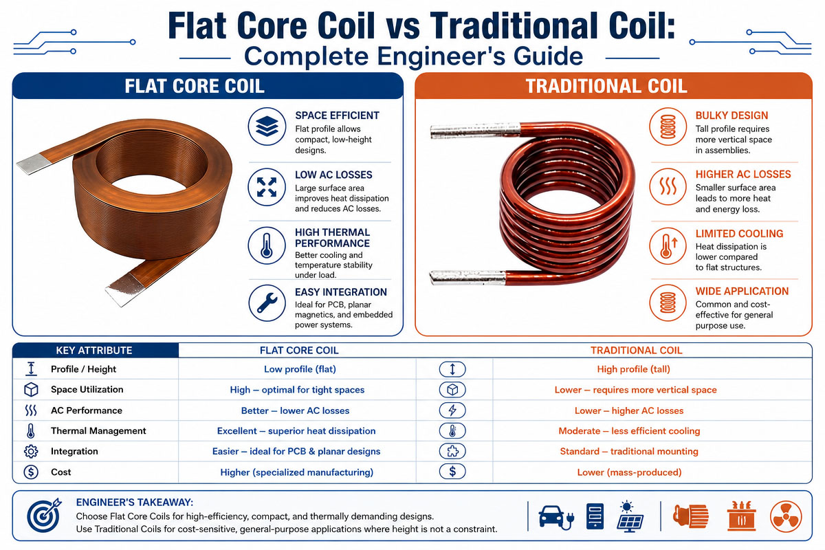
Copper Flat Core Coil vs. Conventional Coil: A Complete Engineer’s Guide

Flat Core Coil vs Traditional Coil Engineer's Guide

Choosing between a copper flat core coil and a traditional round-wire coil for designing the electromagnetic system is determined by the needs of the specific application in terms of electrical, thermal, magnetic, mechanical, and manufacturing properties. Neither one of these designs is better all the time. The right choice depends on the specification of the whole system.

Conductor Shape

The conventional coils are made of the multi-layered round copper wire. The Copper Flat Core Coil uses the flatter form factor for the conductor, which provides a different relation between the conductor cross section, height, and installation envelope.

The flat form factor can offer more flexibility in design in case of critical height constraints.

Electrical Performance

Both of these designs provide excellent electrical conductivity. The resistance is a function of the conductor’s cross-sectional area, length, temperature, connection quality, and turns.

The flat conductor can be designed in such a way that it would have a large area of conductivity and high current-carrying capacity in the given package. Electrical and thermal testing has to be conducted to verify the current carrying capacity.

Thermal Control

The generation of heat is one of the major aspects in coil design. Electrical losses leadIf the heat does not dissipate sufficiently, it can affect reliability. be affected.

The flat form factor can offer increased surface area for dissipation. It can also increase the thermal contact with the heat-spreading structure. Nevertheless, the actual thermal performance is a function of the whole assembly and not only the form factor of the conductor.

Space Utilization

Space Utilization is the field in which the flat construction can provide significant advantage. Both the automotive and industrial sectors demand smaller and smaller components.

The well-designed Copper Flat Core Coil can be designed in the limited installation envelope, which allows optimizing the length, width, height, terminals, and mounting points.

The traditional round wire coils still remain highly applicable in those applications where traditional winding techniques can provide the adequate performance and cost advantage.

Magnetic Characteristics

The magnetic performance is determined not by the conductor form factor but by the number of turns, current, core material, magnetic path, air gap, saturation, and operating frequency.

The flat coil can be a highly efficient part of a well-designed magnetic circuit. Nevertheless, switching from the traditional to the flat coil design does not guarantee increased magnetic force or inductance.

Manufacturing

The winding processes of conventional round wire coils are quite well-established and can be economical for many standard designs.

The Copper Flat Core Coils can require specialized forming, stamping, bending, insulation, tooling, or assembling processes. Custom industrial products should take the additional manufacturing requirements into account at the design stage.

Price

The final cost will depend on the material cost, tooling, production volumes, manufacturing complexity, assembling time, testing requirements, and performance needs.

For the high volumes of the automotive applications, the custom flat coil can be justified by the tooling cost, as it provides the better package and performance, resulting in system-level benefits.

Reliability

Any of these designs can be highly reliable over time if they are well designed. Reliability is determined by the insulation, quality of the conductor, connections, thermal management, mechanical strength, environmental protection, and manufacturing consistency.

For automotive applications, validation testing should include vibration, temperature, cycling, humidity, and electrical cycling.

Which design should the engineers choose?

In case compact geometry, high conductivity, thermal management, customization, and integration into the limited installation space are important for the design, it is better to use a copper flat core coil.

In case manufacturing complexity, standard dimensions, or cost efficiency are more important than the conventional winding, it is better to use the traditional round wire coil.

The best engineering approach is not only to compare the coil form factors. It is the comparison of the two technologies in the identical voltage, current, resistance, inductance, temperature rise, duty cycle, dimensions, magnetic performance, lifetime, and cost requirements.

The prototype testing prior to the design is highly recommended for the automotive and industrial applications.

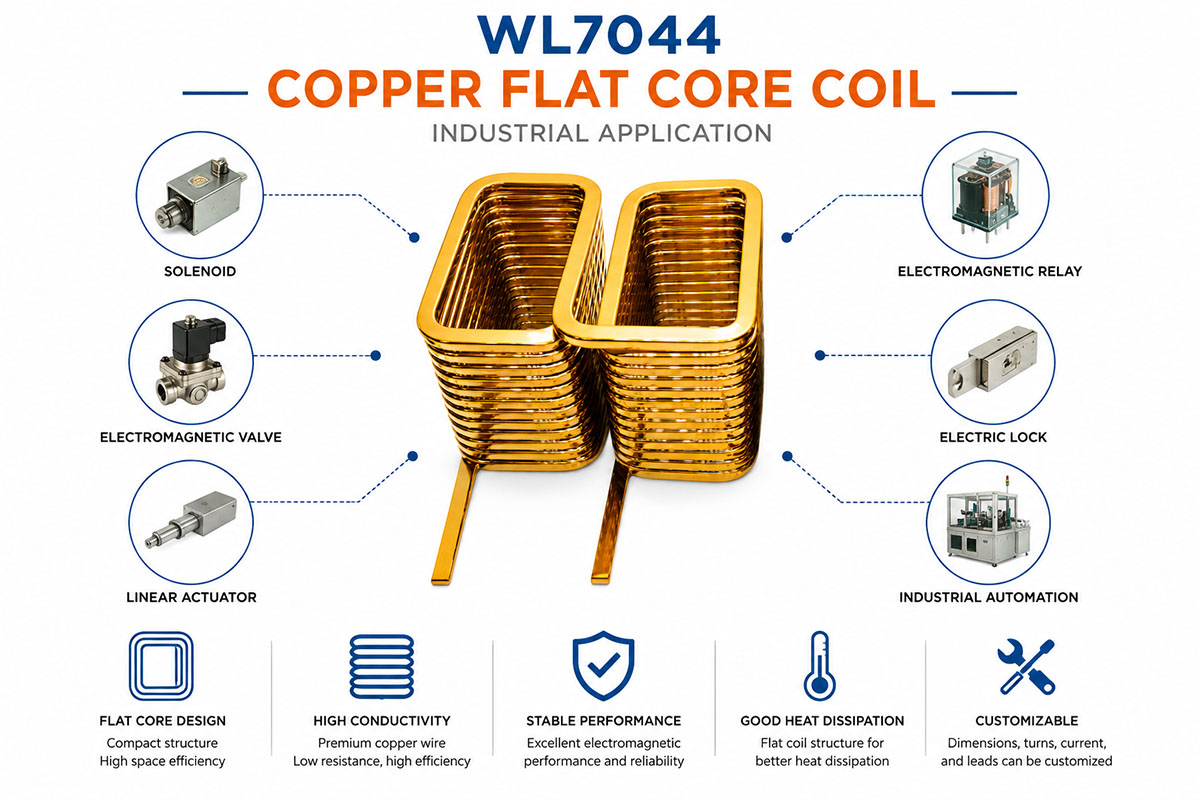
Copper Flat Core Coil Industrial Application

Copper Flat Core Coil Industrial Application Guide

The Copper Flat Core Coils can be used in a variety of automotive and industrial applications requiring compact electromagnetic components, efficient electrical conduction, and heat dissipation.

In the automotive industry, they can be designed for electric vehicles, charging systems, battery management equipment, motor control systems, automotive actuators, relays, sensors, electronic control modules, and other electromagnetic assemblies. Many applications of EV require components capable of reliable operation in restricted installation spaces under electrical and heat loads.

Copper flat core coils are used in industrial automation, electromagnetic actuators, control equipment, power conversion systems, industrial sensors, machinery, and automated production equipment.

They are also applicable in power electronics, including power supplies, DC systems, inverters, energy storage equipment, and electrical control systems. Small geometry allows engineers to optimize available installation space.

Other applications include robotics, renewable energy equipment, battery systems, electromagnetic clutches, industrial control modules, and custom electromechanical products.

The final design application will determine required copper size, resistance, inductance, voltage, current, heat rise, core material, duty cycle, and mechanical sizes. Proper engineering validation prior to mass production is a must.

Why are Copper Flat Core Coils gaining popularity for Automotive System Solutions?

The increasing popularity of the Copper Flat Core Coil technology among the automotive solutions is closely connected with the necessity of the industry to develop smaller, lighter, efficient, and reliable electrical components.

Modern automobiles have many more electronic and electromagnetic systems as compared to the traditional ones. In addition, electric cars increase the demand for efficient power management, motor control, battery systems, charging equipment, sensors, actuators, relays, and electronic control modules.

Copper is a highly attractive material due to its high electrical and thermal conductivity. These properties can be beneficial for engineers when designing efficient coils.

Another important feature is the flat form factor. Usually, the automobile systems have limited installation space, which is why engineers have to identify components that would be able to provide the required electrical and electromagnetic performance in the compact package.

The available mechanical envelope will allow designing a copper flat core coil. The thickness and width of the conductors, turns, resistance, inductance, core construction, position, and dimensions of the terminals can be optimized for each specific application.

However, performance alone is not enough for automotive applications. The coil has to withstand vibration, temperature changes, humidity, electrical cycling, and long life.

Thus, high conductivity, compact geometry, thermal potential, and design flexibility make the Copper Flat Core Coil technology a valuable solution for next-generation automotive and EV systems.


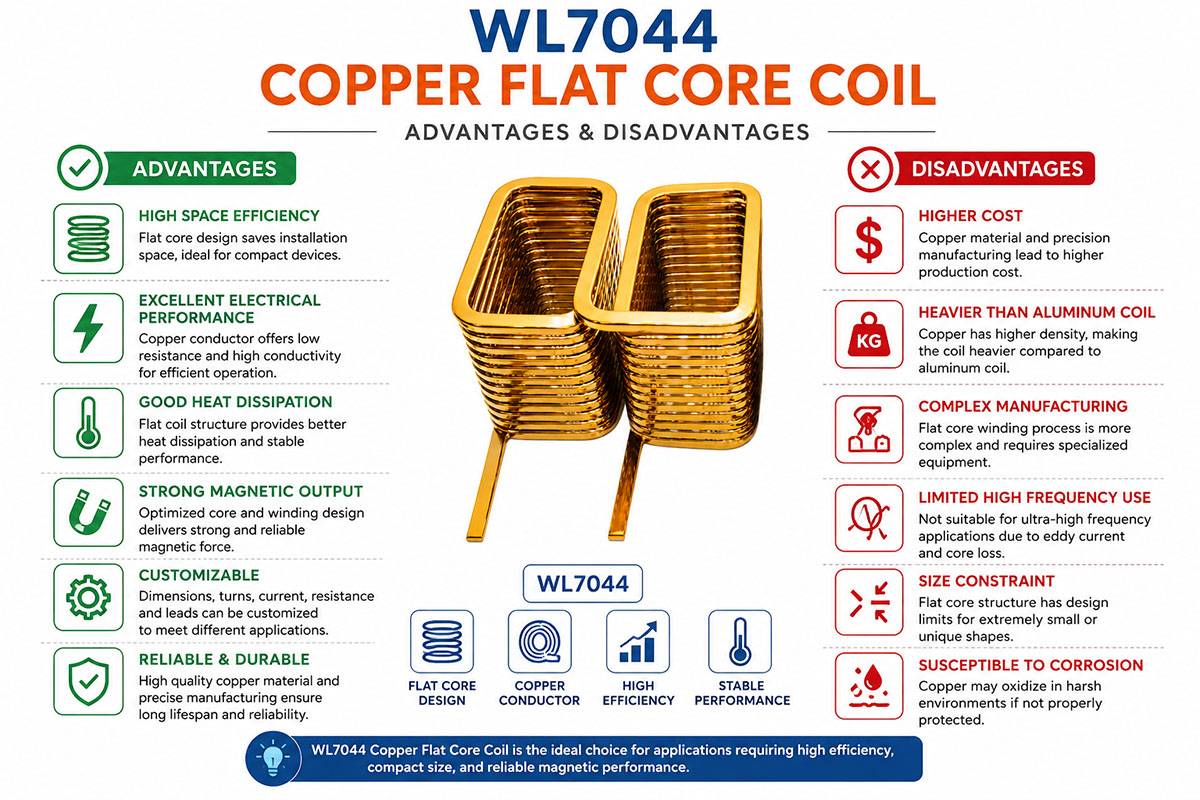
Compact Copper Flat Core Coil Advantage and Disadvantage

Copper Flat Core Coil advantage and Disadvantage

Compact Copper Flat Core Coil Advantages

Firstly, the greatest advantage of using a copper flat core coil is the superior conduction with small geometry. Copper is a vereffectiveod conductor both in terms of electricity and thermals. If designed well, it can also help to reduce resistance and thermal losses.

Secondly, the flat form factor provides a potential for effective use of the installation space. In some cases, it makes it possible to install a larger conductor cross section in a limited height compared to the traditional construction.

Thirdly, the other advantages of such a coil are the possibility of adjustable sizes, flexible mounting, good electromagnetic performance, and applicability for automation.

Compact Copper Flat Core Coil Disadvantages

Firstly, as compared to the traditional aluminum, the copper is a much heavier and costlier material, which might increase the price of materials and the weight of the components.

Secondly, depending on the design, the flat conductors might require some specialized processing, insulation, tooling, or assembly.

Thirdly, it should be noted that the flat geometry does not necessarily provide better electrical or thermal performance. Its efficiency largely depends on the dimensions of the conductors, their number, insulation, cooling and conditions, magnetic design and operating duty cycle.

Fourthly, the design can become complicated if the coil has to satisfy several strict criteria in terms of geometry, thermals, magnetism, and mechanics at once.

Therefore, the technology of the Copper Flat Core Coil is especially valuable if the conductivity, compactness, thermals, and customized geometry justify it.

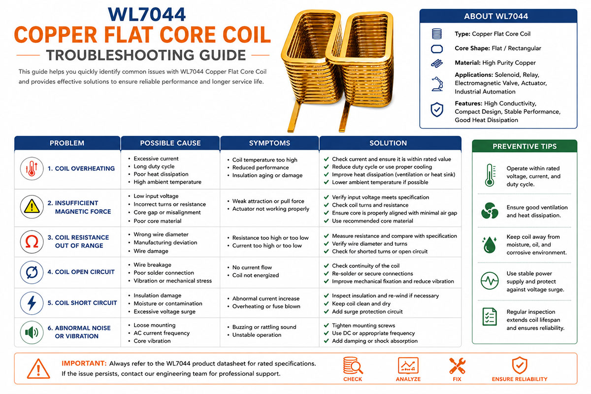
Troubleshooting Copper Flat Core Coil

Copper Flat Core Coil Troubleshooting Guide

If the Copper Flat Core Coil does not operate properly, the troubleshooting process should start from checking the electrical performance and continue with thermal, magnetic, and mechanical parameters.

Over Temperature

Checking the operating current, resistance, duty cycle, ambient temperature, cooling, and installation space. Excessive current and insufficient cooling can lead to overheating.

Poor Magnetic Performance

Checking the voltage, current, turns, core material, air gap, magnetic circuit, and core saturation. Incorrect air gap and insufficient current can seriously impair the magnetic performance.

High Resistance

Checking the resistance of the coil against the design. Checking the sizes of copper conductors, connection points, joints, and terminal resistance.

Inductance is Not Correct

Firstly, confirming the test frequency and measurement conditions. Secondly, checking the number of turns, core material, air gap, and geometry of the coil.

Short Circuit, Electrical

Checking the insulation between turns, edges of the conductors, terminals, and core. The insulation can be damaged mechanically during the forming or assembling process.

Issues with Mechanical Installation

Checking the dimensions of the coil, its mounting position, terminal direction, lead length, and potential interference with other components.

Uneven Performance

Comparing the samples under the same voltage, current, temperature, and duty-cycle conditions. Checking the manufacturing tolerances.

The systematic troubleshooting will allow finding out whether the problems concern the electrical design, magnetic design, thermal management, manufacturing, or assembly.

Compact Copper Flat Core Coil FAQs

1. What are the main advantages of the Copper Flat Core Coil?

They have high electrical conductivity, good thermal conductivity, compact construction, high current capability, flexible geometry, and customization options. The flat conductor can help to optimize the coil for the limited installation space. The actual performance is determined by the conductor size, coil geometry, core material, operating current, duty cycle, and thermals, however.

2. What are Copper Flat Core Coils used for?

They are used in automotive systems, electric vehicles, battery systems, charging equipment, industrial automation, power supplies, inverters, sensors, actuators, electromagnetic devices, robotics, and energy systems. They are especially valuable when compact size, efficient electrical conduction, and thermal management are important design considerations.

3. Is the Copper Flat Core Coil Better Than Conventional Round Wire Coil?

Not always. Every design has its advantages. The flat-core copper coil can offer better space utilization, conductor flexibility, and thermal contact potential, while traditional round-wire coils can be easier and more economical to manufacture. The engineers should compare resistance, inductance, current capacity, temperature rise, dimensions, magnetic performance, cost, and lifetime before the choice.

4. Is it possible to have a custom-made flat core coil?

Yes. The Copper Flat Core Coils are designed for specific applications. The customization options are the thickness of the copper, conductor width, number of turns, size of the coil, resistance, inductance, core material, terminal shape, lead length, mounting structure, and insulation. If the design is high volume or very specialized, the custom tooling or forming is necessary.

5. How to Avoid Overheating of Copper Flat Core Coil?

Overheating can be avoided by choosing the proper cross section of the copper conductor, managing the resistance and operating current, optimizing the duty cycle, improving the cooling, and providing the sufficient installation clearance. In the design phase, the ambient temperature, continuous operation time, cooling, and maximum admissible temperature rise should be considered.

6. What Information Should Be Provided to the Copper Flat Core Coil Manufacturer?

To ensure the correct design and quotation, please provide as much of the following information as possible:

  • Operating Voltage
  • Operating Current
  • Resistance
  • Inductance
  • Size of Coil
  • Core material or magnetic requirements
  • Operating Frequency
  • Cycling Duty
  • Temperature Range
  • Required Lifetime
  • Space for Installation
  • Terminal or Lead Specifications
  • Application and Environment of Operation

How to Choose A Copper Flat Core Coil

Selecting a copper flat core coil involves much more than just choosing a coil based on its size and resistance. The coil should meet all the electric, mechanical, thermal, and application needs.

1. Ensure the voltage and current requirements

Start with defining the operating voltage, e.g., 5 V, 12 V, 24 V, or 48 V DC. Let’s calculate the maximum allowable current.

The relationship between voltage, resistance, and current is

I = V / R

where:

I = current, V = operating voltage, R = coil resistance

Consider your resistance wisely to provide enough current flow with acceptable heating.

2. Calculate the inductance requirements

The inductance determines how the coil reacts to changes in the current. Higher inductance means more energy storage but lower electric response speed.

Consider the following:

  • Inductance needed
  • Frequency of operation
  • Switching rate
  • Response time
  • Requirements for magnetic circuit

The inductance and parasitics of the coil should be considered jointly in high-speed applications.

3. Consider the size of the coil.

Consider the available installation space before finishing the coil design.

Important dimensions are the following:

  • Outside Diameter
  • Inside diameter
  • Height of coil
  • Copper conductor width and thickness
  • Core dimensions
  • Terminal location
  • Structure for mounting

In case of limited installation space, the compact flat core can be used. But the significant reduction of the size of the coil may lead to increased resistance and heating.

4. Choose the Right Copper Conductor

It is highly conductive, making it suitable for efficient electricity transmission.

Factors to consider:

Conductor width, thickness, length, and cross section (flat copper coil)

  • Resistance—
  • Capacity (current)
  • Temperature rise
  • Energy consumption
  • Robustness in mechanics

The copper conductor should be chosen based on both the continuous and the peak current requirements.

5. Thermal Performance Test

The heat generation is one of the key aspects of coil design.

Estimate the loss of copper:

P = I²R

Now, you should eliminate the heat. Consider the following:

  • Running time (non-stop)
  • Cycle d’usage
  • Environmental Temperature
  • Maximum allowed coil temperature
  • Heat dissipation through core and housing
  • Temperature rating of insulation

The coil, showing satisfactory results in a short laboratory test, may overheat in continuous operation.

6. Consider the Core Material

The choice of core material affects the magnetic properties of the coil. The core material selection depends on the application.

Consider the following:

  • Permeability (magnetic)
  • Characteristics of saturation
  • Operating frequency
  • Loss of core
  • Magnetic strength needed
  • Operating temp.

Thus, the design of the copper conductor and the magnetic core should be considered as a complete electromagnetic system, not two separate entities.

Tips to Avoid Common Mistakes in Copper Flat Core Coil Design

Many design problems with coils arise not from manufacturing defects but from insufficient or incorrect specifications during the design stage.

1. Do Not Limit to Voltage

One of the mistakes is limiting yourself to the following information:

“I need a coil of 24 volts.”

The voltage does not provide any information about the appropriate coil.

Provide the necessary current, resistance, inductance, duty cycle, operating frequency, and working temperature, if available.

2. Take into Account Duty Cycle

The coil with a 1-second-per-minute duty cycle has completely different thermal requirements compared to the continuous one.

State clearly if the application is

  • Duty continuing
  • Intermittent duty
  • Pulse mode
  • High Frequency Chopping

This factor has a major influence on the size of the copper conductor and winding.

3. Do not Design at Room Temperature

One of the frequent mistakes is the testing of the coil at about 20-25°C and the expectation of the same performance in the actual application.

Consider the maximum ambient temperature and temperature rise during the operation.

4. Make the Coil Big Enough

Miniaturization is crucial, but excessive reduction of the cross section of the conductor or the winding space leads to increased resistance and heat generation.

The optimal design is not the smallest coil, but the smallest coil that can reliably satisfy the electrical and thermal requirements.

5. Take Tolerences Into Account

The design stage should consider the manufacturing tolerances.

The acceptable tolerances are provided for:

Resistance 3

Inductance • Size

Copper Thicknesses

Width of conductor

Core size

Terminal position

The realistic tolerances result in reduced manufacturing cost for high-volume production.

6. Ensure Mechanical Compatibility

Make sure before releasing the final drawing that the coil fits correctly with the mating parts.

Consider carefully the following points:

  • Core clearance
  • Holes for mounting
  • Terminal orientation
  • Position of connector
  • Clearance for insulations
  • Assembly instructions

The coil can meet all the electrical specifications and still fail because of improper assembling.

7. Review the entire system

Finally, do not evaluate the copper flat core coil as a separate component.

Test the performance with the power supply, magnetic core, PCB, controller, casing, heat sink, and surrounding components.

Such an approach prevents problems like overcurrent, electromagnetic interference, overheating, poor magnetic performance, or slow response.

Design Checklist

Custom Copper Flat Core Coil Prior to order placement, please prepare the following information:

Parameter Recommended Information
Operating voltage 5 / 12 / 24 / 48 VDC, etc.
Current Required operating current
Resistance Target resistance and tolerance
Inductance Target inductance and tolerance
Frequency Operating/switching frequency
Duty cycle Continuous or intermittent
Dimensions OD, ID, height, conductor size
Core Material and dimensions
Temperature Ambient and maximum operating temperature
Insulation Required insulation rating
Terminals Type and position
Application Motor, sensor, actuator, power electronics, etc.
Quantity Prototype and annual production volume

Quantity, prototype, and yearly production volume

The main principle: design the coil considering the electrical, thermal, magnetic, and mechanical requirements, not simply selecting the copper coil according to the voltage or dimension.


Get A Free Quote Now

Contact Form

Related Products

Related News

Scroll to Top

Get A Free Quote Now !

Contact Form
If you have any questions, please do not hesitate to contact us.
Weilong Solenoid Company Culture