Mini Push-Pull Frame Solenoid Factory Automation Guide
Mini Push-Pull Frame Solenoid - Locking Mechanisms Guide
Mini Push-Pull Frame Solenoid Automation Robotics Guide
Mini Push-Pull Frame Solenoid Performance Control Guide
Mini Push-Pull Frame Solenoid OEM Troubleshooting Guide
Mini Push-Pull Frame Solenoid Medical Integration Guide
Mini Push-Pull Frame Solenoid Factory Automation Guide
Mini Push-Pull Frame Solenoid - Locking Mechanisms Guide
Mini Push-Pull Frame Solenoid Automation Robotics Guide
Mini Push-Pull Frame Solenoid Performance Control Guide
Mini Push-Pull Frame Solenoid OEM Troubleshooting Guide
Mini Push-Pull Frame Solenoid Medical Integration Guide

WL0416 Mini Push-Pull Frame Solenoid For Medical Control Solutions

The Mini Push-Pull Frame Solenoid is a small electromagnetic actuator that is created for devices that require quick and reliable linear motions in limited installation spaces. Through its frame-style design, engineers can tune the coil, plunger, mounting holes, stroke, and force based on the application needs.

The Mini Push-Pull Frame Solenoid can function in push, pull, or spring return configurations according to its design. Voltage, current, power consumption, stroke, initial force, end force, duty cycle, response time, temperature rise, and expected lifetime are some of its essential specifications. Industrial automation, robots, medical equipment, point-of-sale devices, security devices, valves, vending machines, and smart devices are just some applications that can integrate the solenoids. The Mini Push-Pull Frame Solenoid OEM applications will be able to customize magnetic circuits, sizes, connectors, shafts, springs, and performance through this product.

Mini Push-Pull Frame Solenoid Product Overview

The Mini Push-Pull Frame Solenoid is a small linear electromagnetic actuator designed for automated devices and equipment with limited space. The frame-style design provides various mounting options while combining the coil, magnetic circuit, and moving plunger in a small package.

Depending on the application requirements, the design can be configured for push, pull, or spring-return motions. Operating voltage, coil power, stroke, push force, pull force, response time, duty cycle, temperature rise, and lifetime are some of its important performance metrics. Overall dimension, plunger diameter, mounting holes, spring properties, connectors, and electrical specifications are some of the OEM customizations. Industrial automation, robots, medical devices, point-of-sale devices, security devices, and other small electromechanical applications can benefit from the product.

How Do Mini Push-Pull Frame Solenoids Work?

A mini push-pull frame solenoid is powered by an electromagnetic force.

Step 1: Applying Electrical Power

A current flows through the copper winding once the coil receives the required DC voltage.

Step 2: Generating Magnetic Field

A magnetic field surrounds the magnetic circuit due to the excited coil.

Step 3: Plunger Movements

The ferromagnetic plunger is attracted to the magnetic pole by the magnetic field attraction force.

Step 4: Generating Linear Motion

Plunger movement is the mechanical output of the solenoid. For the push or pull function, the output can be configured accordingly.

Step 5: Reverse Motion

The plunger returns to its original position due to the return spring or external mechanical force once the power is removed.

Key Design Principle

The following factors influence the actual output force:

Air gap, plunger shape, stroke, magnetic circuit, coil design, and operating voltage.

As a result, a solenoid should be selected based on the force at a certain stroke rather than merely force.

Key Features of the Mini Push-Pull Frame Solenoid

The Mini Push-Pull Frame Solenoid combines compact design and controlled electromagnetic linear motion. Some of its important features include a compact frame design, configurable mounting dimensions, short stroke operation, and adjustable push-pull configurations. Engineers can customize the plunger, spring, coil, and mounting frame through its open frame design that can also facilitate mechanical integration. Using a proper coil design, various DC voltage and power can be accommodated.

Depending on the application, the solenoid can be designed for cycling, intermittent, or fast response. Force, stroke, duty cycle, temperature rise, noise, response time, and lifetime are some of its common design considerations. Connectors, shaft diameter, return springs, surface treatment, mounting holes, and other mechanical interfaces are some of the OEM customizations.


Mini Push-Pull Frame Solenoid Product Video

Mini Push-Pull Frame Solenoid Detailed Display

Mini Push-Pull Frame Solenoid Technical DataSheet

Brand Weilong Technology Model Number WL0416
Rated Voltage (V) DC 3-12V Rated Power (W) 5–10 W
Work Model PUSH-PULL Type Holding Force (N) 0.2–0.6 N
Stroke (mm) 1–5 MM Reset Time(s) 1 S
Service Life 300 Thousand Times Certification CE, RoHS, ISO9001,
Material Carbon Steel Housing with Zinc-Plated Coating Lead Wire Length (mm) 200
Install Style Adjustable Screw Tolerance of Dimension ± 0.1 MM
Water-proof None Insulation Class F 155 Cel. Degree
Hi-Pot Test AC 600V 50/60Hz 2s Non-excitation Holding Force 0
Working Temperature -10°C-100°C Duty Cycle 1-100%
Thread Depth (mm) / Payment Term TT, or LC at Sight
Sample Order Yes. Warranty 1 Year
MOQ 500 pcs Supply Ability 5000 pcs per week
Delivery Time 30 Days Port of Loading Shenzhen

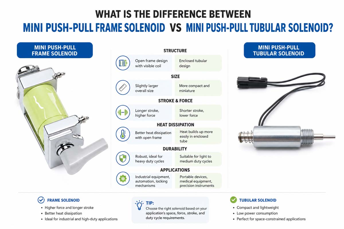
Mini Push-Pull Frame Solenoid vs. Mini Push-Pull Tubular Solenoid

Mini Push-Pull Frame vs Tubular Solenoid Different Explians

Feature Mini Push-Pull Frame Solenoid Mini Push-Pull Tubular Solenoid
Structure Open-frame construction Enclosed tubular construction
Size Optimization Highly flexible for custom mounting Compact cylindrical package
Mounting Flexible mounting holes and brackets Usually axial/radial tubular mounting
Customization Easy-to-customize frame and mounting structure Strong customization potential for diameter and length
Environmental Protection Generally lower unless additional protection is added Generally better mechanical protection
Heat Dissipation Open structure can support heat dissipation Enclosure may affect thermal management.
Mechanical Integration Excellent for customized equipment structures Excellent where cylindrical space is available
Appearance Exposed frame and coil structure More enclosed and finished appearance
Typical Applications Automation, POS, robotics, compact mechanisms Locks, valves, automation, medical and industrial devices
Best Choice When Mounting flexibility and custom frame geometry are priorities. A compact, enclosed cylindrical actuator is preferred.

Which One Is Best for You?

If you need flexible installation, customized frame geometry, easy integration, and efficient space utilization, choose the Mini Push-Pull Frame Solenoid.

If you have enough hole or tubular installation space and prefer a cylindrical and more enclosed structure, choose the Mini Push-Pull Tubular Solenoid.

Rather than just comparing the outer dimensions, the ultimate choice for the OEM projects should be made taking into account such factors as force, stroke, voltage, duty cycle, thermal conditions, installation space, environmental requirements and desired lifetime.

Are You Trying to Find a Custom Mini Push-Pull Frame Solenoid?

Tell us about the force, stroke, voltage, duty cycle, installation dimensions, and lifespan goals you need. Based on the assessment of mechanical design, coil configuration, and magnetic circuit, a certified solenoid manufacturer can suggest to you the proper OEM solution.


Mini Push-Pull Frame Solenoid Industrail Applicaion

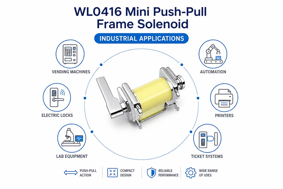
WL0416 Mini Push-Pull Frame Solenoid Industrial Application

A small push-pull frame solenoid is commonly used in devices that require small and repetitive linear actuation. In industrial automation, they can be used to control mechanical locks, gates, switches, clamps, feeds, and positioning mechanisms. The solenoids can offer additional linear movements for grasping, releasing, or locking mechanisms in robots. Depending on the system requirements, miniature solenoid actuators can be used in medical devices for mechanical interlock, fluid control mechanisms, sample handling, and disposable cartridge systems.

The mini push-pull frame solenoid can also activate paper guides, cutters, locks, and mechanical release mechanisms in POS and office equipment. Additionally, vending machines, security devices, laboratory equipment, smart appliances, and automated control devices are some of the applications that can utilize the solenoids. Their small frame design is particularly useful when there is limited installation space. OEM applications will be able to customize force, stroke, voltage, duty cycle, mounting dimension, and return mechanism for better mechanical and electrical integration.

Why Are Smart Medical Device Solutions Using the Mini Push-Pull Frame Solenoid?

As a result of the increased need for compact, automated, and repeatable mechanical motion in contemporary systems, mini push-pull frame solenoids have become more and more popular in smart medical and laboratory equipment.

As a result of the need to house electronics, sensors, pumps, valves, batteries, and communication modules within a small enclosure, medical equipment often has limited interior space. Short linear motion can be easily performed with the help of the mini frame solenoid without the necessity of a large motor and mechanical transmission system.

Among potential applications are

Cartridge locking and release mechanism

Sample processing mechanisms

Mechanical interlock

Door lock and cover locking mechanisms

Small valve mechanisms

Disposable cartridge positioning

Automated laboratory mechanisms

Diagnostic instruments

Reagent management systems

Another advantage of the solenoids is simple electrical control. For automated equipment systems, solenoids are appropriate because they can be operated by the electronic control system.

However, it does not mean that any miniature solenoid is appropriate for medical applications. In accordance with the final device, engineers should check the cleanliness, material, temperature, reliability, noise, electromagnetic compatibility, longevity, and applicable regulations.

The technology is useful for many smart medical device mechanisms because of its compactness, direct linear motion, configurable geometry, and relative simplicity of control.

Mini Push-Pull Frame Solenoid Advantage and Disadvantage

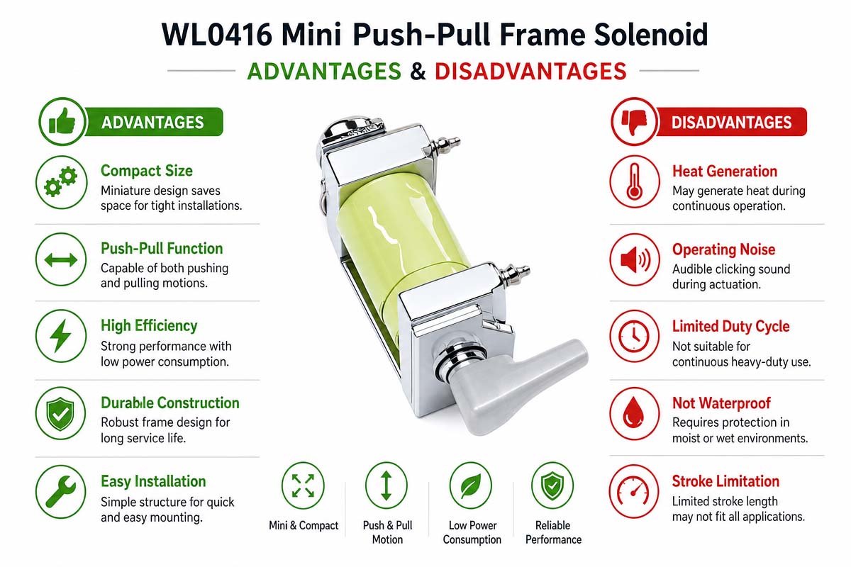
WL0416 Mini Push-Pull Frame Solenoid Advantage and Disadvantage

Mini Push-Pull Frame Solenoid Advantage

Little push-pull frame solenoids offer several advantages for small electromechanical systems. These solenoids suit applications with limited installation space because of their compactness. No complicated transmission system is needed for linear actuation, owing to the simple electromagnetic operating principle. The flexibility of mounting and OEM customization are also possible with the help of the frame style design. They are able to deliver repetitive movement and rapid response when properly designed. Engineers are able to optimize actuator to perform in certain applications through the coil, plunger, spring and frame combinations.

Mini Push-Pull Frame Solenoid Disadvantage

Yet there are also some limitations. The force can be reduced in certain positions along the stroke since the solenoid force varies depending on the plunger position. Coil heating can be one of the limitations during continuous or high-duty operation. In comparison to other types of actuators, the power consumption can also be quite substantial. The proper mechanical alignment is required in order to avoid additional wear and friction. Compared to the fully enclosed tubular type, the open-frame design can provide less environmental protection. Last but not least, load conditions, voltage stability, temperature regulation, and magnetic circuit design play a significant role in the performance. Therefore, comprehensive application testing is required before the series production.

Mini Push-Pull Frame Solenoid Troubleshooting Guide

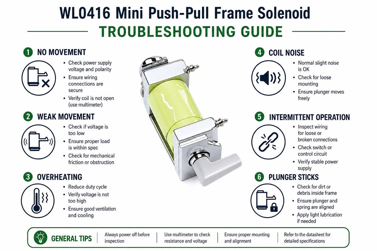
WL0416 Mini Push-Pull Frame Solenoid Troubleshooting Guide

Problem 1: The solenoid does not move.

Check:

Voltage of the power supply

Coil continuity

Connector and wiring

Driver output

Mechanical blockage

Coil resistance and supply voltage are able to be checked with the help of a multimeter.

Problem 2: The insufficient force

Potential causes include:

Incorrect voltage

Excessive stroke

Overpowering external load

Incorrect plunger location

Magnetic circuit variation

Mechanical friction

Force should not be measured at the start only. It is necessary to measure force at the specified stroke.

Problem 3: Overheating Solenoids

Check:

Duty cycle

Power consumption from coils

Surrounding air temperature

Supply voltage

Energization time

Heat dissipation

Thermal design analysis is required before raising the voltage to compensate for the force lack.

Problem 4: Sluggish Plunger Movement

Load, spring force, mechanical friction, coil characteristics, and power supply should be analyzed. Mechanical resistance can significantly slow down the speed of the response.

Problem 5: Excessive Noise

Return spring properties, mechanical clearance, mounting rigidity, and plunger impact should be examined.

Problem 6: Unstable Motion

Contamination, mechanical misalignment, voltage instability, dimensional changes, or excessive friction can cause this problem.

Recommended Troubleshooting Approach

Mechanical → Electrical → Magnetic → Thermal → Load → Control System

Before changing the OEM product design, the parameters of the approved sample should be checked against test results.

Mini Push-pull Frame Solenoid FAQs

1. How the intermittent duty cycles differ from the continuous duty cycles?

The mini push-pull frame solenoids generate heat quickly because of their small surface area:

  • Continuous Duty (100%): Less force is generated, but it is designed to operate continuously without overheating.
  • Intermittent Duty (<50%, e.g., 10% or 25%): Allows sufficient cool-down time, allows using higher voltage and current for short pulses, providing noticeably more force without melting the coil insulation.
2. How does pulling/pushing force vary with stroke length?

There is an inverse non-linear relationship between force and stroke length. At the zero stroke length, where the plunger is fully seated, the small solenoid generates maximum force (holding force). The initial start force decreases rapidly with the increasing stroke length.

3. What are the usual voltage and power requirements?

The Mini Push-Pull Frame Solenoid powered with DC works at standard voltages of 5V, 6V, 12V, or 24V DC. Power consumption varies from 1W to 10W, depending on the size and duty cycle ratings.

4. Are tiny DC solenoids polarized?

In the case of non-latching devices, regardless of the lead connection to the positive or negative, the plunger will draw inward for the mechanical stroke. However, polarity becomes important if:

  • An in-built flyback protection diode is used in the device.
  • A bistable magnetic latching solenoid is used.
5. Why flyback diode is needed in the solenoid circuits?

As soon as power to the solenoid coil is cut off because of the collapsing magnetic field, inductive kickback or a high-voltage reverse spike occurs. This voltage safely dissipates through the flyback diode (like 1N4001/1N4007), which is connected in reverse parallel to the solenoid leads.

6. What are the common applications for small frame solenoids?

Due to their compactness and fast response time (less than 50 ms), small frame solenoids are often used for:

  • Smart latches and electronic door/cabinet locks
  • Coin acceptors and vending machines
  • Small fluid valves and medical diagnostic equipment
  • Thermal printers and automated ticket dispensers
  • Robots and small sorting systems

How to Choose a Mini Solenoid Push-Pull Frame

The solenoid should be chosen based on the actual application requirements instead of simply picking the smallest model.

1. Identifying Required Force

Calculate the push and pull forces under actual operating conditions. Since the solenoid force depends on the plunger position, it is important to determine the force at a required stroke.

2. Describing Stroke

Determine the amount of mechanical travel that is actually needed. Avoid choosing excessive stroke since it may affect force, speed, and power requirements.

3. Verifying Operating Voltage

Specify the available DC voltage, such as 5 V, 12 V, 24 V, or other required voltage. The coil should be designed according to the actual power source.

4. Determining Duty Cycle

Determine how often the solenoid will run and how long it will remain electrified. Different thermal designs are required for intermittent and continuous duty solenoids.

5. Examining Installation Space

Provide the maximum length, width, height, and mounting hole positions that are allowed. The space for plunger movement should also be considered.

6. Evaluating Reaction Time

It is important to specify the required pull-in and release times for high-speed automation.

7. Considering Temperature

Verify the ambient temperature and allowable coil temperature rise. Thermal conditions can significantly affect reliability.

8. Describing Lifetime

Depending on the application, specify the expected number of operational cycles, such as 100,000 or higher.

9. Examining Mechanical Load

Consider alignment, external load, friction, and spring force. Rather than running continuously at its maximum, the solenoid should have a force buffer.

10. Describing OEM Customization

Talk to the manufacturer about custom coil winding, frame size, plunger geometry, spring properties, mounting interface, and connectors for high-volume applications.

It is recommended to provide the manufacturer with voltage, force, stroke, duty cycle, installation dimensions, and lifetime requirements before requesting a quote.

How to Avoid Common Mistakes During Mini Push-Pull Frame Solenoid Design

Mistake 1: Selecting solely by force

The solenoid force depends on the plunger location. The force should always be provided at a certain stroke.

Mistake 2: Overlooking the Duty Cycle

If a solenoid designed for intermittent operation is used in a continuous duty cycle, it may overheat.

Mistake 3: Applying Incorrect Voltage

Voltage changes can significantly affect temperature, power consumption, and current.

Mistake 4: Overlooking Return Force

To return against spring force, the solenoid should overcome the external load. Calculate the total mechanical load.

Mistake 5: Providing Insufficient Installation Space

Enough alignment and plunger movement space should be provided.

Mistake 6: Overlooking Increased Temperature

Increased coil temperature can affect performance, insulation lifetime, and surrounding components.

Mistake 7: Designing Without Considering Tolerances

Proper dimensional tolerances should be provided in the plunger, frame, mounting holes, and mechanical interfaces.

Mistake 8: Testing without Load

Realistic mechanical load and operating conditions should be considered in the final design.

Mistake 9: Overlooking Endurance

Prototype performance does not necessarily guarantee long-term reliability. Conduct the necessary cycle testing.

Mistake 10: Buying Samples without Proper Specifications

Identify the voltage, force, stroke, duty cycle, mounting dimensions, and operational conditions prior to sampling.


Get A Free Quote Now

Contact Form

Related Products

Related News

Scroll to Top

Get A Free Quote Now !

Contact Form
If you have any questions, please do not hesitate to contact us.
Weilong Solenoid Company Culture
