Latching Solenoid Actuator for Industrial Control
DC Latching Solenoid Actuator for Automation Use
Compact Latching Solenoid Actuator for Devices
Latching Solenoid Actuator for Industrial Control
DC Latching Solenoid Actuator for Automation Use
Compact Latching Solenoid Actuator for Devices

WL1240 Industrial Latching Solenoid Actuator Solutions

A latching solenoid actuator is made to remain latched into position even without continuous electrical power feeding through it. In this case, a permanent magnet provides the holding force, meaning that once the actuator assumes either the retracted or extended position, a latching solenoid actuator can remain in place with no energy. Standard solenoids, on the other hand, will continue to consume power and require it to remain in the given position. A latching solenoid actuator has two possible states, namely extended and retracted, both being stable without additional energy input. A change in position occurs when a pulse of electricity is delivered in one direction to lock, and another pulse is given but in the opposite direction to unlock.

Key features of a latching solenoid actuator

Zero holding power; the actuator holds its position due to permanent magnets. Pulsed power operation: only temporary electrical pulses are needed to change positions. Bi-stability: two possible stable positions

Minimal heat output Energy-efficient, with much lower battery power consumption comparing to standard solenoids Medium force generates enough holding force proportional to the size. Magnetic latching retains the position in case of power failure.


Latching Solenoid Actuator Product Overview

A latching solenoid actuator is a bistable actuator driven with alternating voltage to change the state. It requires only two short impulses of voltage to lock or unlock the actuator, respectively, while using almost no power when not switching. This feature provides minimum power dissipation, heat production, and energy consumption, as well as maintains a state in case of a power outage. Common shapes include tubular, box-frame, and rotary types. The force ranges from a couple of newtons to over 100. As a rule, a latching solenoid actuator is used with small batteries or capacitor discharge drives, which makes them perfect choices for portable or IoT-based systems. Though slower and weaker than continuously driven solenoids, latching actuators are very energy-efficient, hence their widespread adoption in smart locks, valve regulators, and car locks.

Latching Solenoid Actuator Video Presentation

Latching Solenoid Actuator Detailed Display

Latching Solenoid Actuator Technical datasheet

Brand Weilong Technology Model Number WL1240
Rated Voltage (V) DC 12V or 24V Rated Power (W) 10-20W
Work Model Push-Pull Type Holding Force (N) 4000 gf
Stroke (mm) 10 MM Customized Reset Time(s) 0.2
Service Life 500 Thousand Times Certification CE, RoHS, ISO9001,
Material Superior Magnet Iron Lead Wire Length (mm) 200 MM
Install Style Screw Tolerance of Dimension  +/-  0.1 MM
Water-proof  None Insulation Class B
Hi-Pot Test AC 600V 50/60Hz 2s Non-excitation Holding Force 0
Working Temperature -10°C-100°C Duty Cycle 1-100%
Thread Depth (mm) / Payment Term TT, or LC At Sight
Sample Order Yes Warranty 1 Year
MOQ 1000 pcs Supply Ability 5000 pcs per Week
Delivery Time 30 Days Port of Loading shenzhen

What factors affect the operation of a latching solenoid actuator

There are several factors that directly impact on the performance of a latching solenoid actuator. The results of their being out-of-sync or not properly configured are poor force delivery, poor latching ability, and poor switching consistency.

⚙️ 1. Coil Design & Electrical Parameters The very core of the actuator is its coil:

Voltage & current level = magnetic field strength
Resistance & wire size = efficiency and overheating
Number of turns = higher number means higher magnetic field strength but slow response rate. Bad design = ineffective actuation or overheating during pulse.

🔋 2. Pulse Energy (Very Important)

The difference between regular solenoids and latching ones is that the former operate with continuous energy input, whereas the latter operate through pulses of energy.
Pulse voltage
Pulse period
Pulse polarity (negative or positive)
Too short = non-operation
Too long = overheating and inefficiency 👉 One of the most common problems in real world usage.

🧲 3. Magnetism Strength

Since magnets don’t require power in order to hold, the holding strength depends entirely upon their strength:
A greater magnet equals a greater holding force
However, harder to release (overkill) balance is the name of the game when it comes to maintaining stability vs releasing capability.

🧩 4. Mechanical Load & Friction External and internal mechanical aspects:

Load force of plunger
Return spring force (if necessary)
Friction inside bearings or in the rail system. Excessive friction or load could prevent the actuator from completing its stroke.

🌡️ 5. Temperature and environmental factors

Effect on both electrical and magnetic components
Higher temperature → higher coil resistance → lower current
Magnets can be affected negatively by high temperature
Moisture and dust → cause friction / rust
👉 Necessary to have the appropriate IP rating.

⚡ 6. Power Supply Stability Voltage fluctuations → inadequate force to actuate

Fluctuating power → unreliable switching 👉 Especially critical for battery-powered or lengthy wiring applications.

⏱️ 7. Required response times

Perfect timing = fast response
Lightweight core and optimized coils
Too heavy plungers delay the process 👉 Mismatch results in delayed or faulty actuation

🧱 8. Magnetic Materials Used in Solenoids’ cores and plungers

Higher permeability materials = greater magnetic flux
Poor quality materials → inefficient operation 👉 Core material selection greatly impacts force generated.

🔧 9. Precision of Manufacturing

Precision of air gaps
Precise plunger & core positioning
Manufacturing tolerances 👉 Any slight deviation in positioning would greatly decrease the efficiency of magnetism.

💡 10. Control Circuits Design

Using the right drive type (H-bridge or pulse)
Correct timing & polarity change
Using protection elements (diodes)
👉 No matter how well the solenoid is designed, bad circuit design leads to poor operation.
🚨 Insight #2 (Engineering of reality)
Real world application problems usually stem not from the solenoid, but rather from:
Defective pulse control
Inadequate Power Supply
Poor mechanical integration

✅ Quick Recap Most critical points include the following:

Voltage x time = pulse energy.
Strength of magnetism balance
Mechanical load & friction
Coil design
Power stability

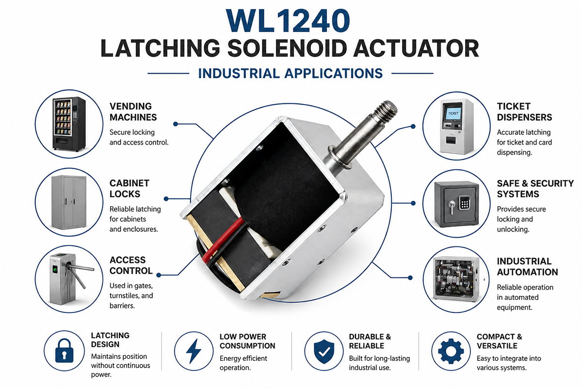
Latching Solenoid Actuator Industrial Application

WL1240 Latching Solenoid Actuator Industrial Application

How does a latching solenoid actuator work?

The latching solenoid actuator’s working principle is based on the interaction between a permanent magnet and an electromagnetic coil. A permanent magnet is responsible for holding the plunger in whatever position, which requires no power. Once a small DC voltage pulse is supplied to the coil, electromagnetic fields are generated that either enhance or interfere with the magnet’s field depending on the polarity of the pulse. If the generated field acts against the permanent magnet’s fields, then the plunger gets released from the lock and changes its position until it meets the second magnet or mechanical stop. If a pulse with another polarity is provided, then the previous locking position is engaged again. What is crucial is that the actuator uses power only for brief moments, typically lasting about 20-100 ms for each change of position. Otherwise, it consumes no power since it works as a bistable switch.

Application of a latching solenoid actuator

A latching solenoid actuator is proven very useful for applications where power conservation and resilience to power loss are essential. These are especially important for smart locks for doors, cabinets, and safes that remain closed in the absence of electricity. EV charging stations utilize a latching actuator to lock the charging plug to prevent unauthorized removal once it is plugged in and consumes no battery power. A latching solenoid actuator can easily remain open or closed to regulate water or gas flows in industrial equipment powered via irrigation or remote solar batteries. In addition, a latching solenoid actuator can be found in household appliances to save electricity, such as laundry machines or dish washers that use a latching solenoid to control water flow. Portable gas flow controllers for oxygen concentrators, e.g., to deliver oxygen in portable ventilators or CPAP machines, are perfect use cases of latching solenoids as well. Moreover, they are found in automotive devices, such as electronic parking brakes or vehicle caps. Factories use these actuators in counting machines. Solar panels and other renewable energy systems use them to control the positioning of solar collectors overnight. Also, they are commonly used in vending machines or locker doors to unlock remotely. In general, wherever control is required, power outage resilience, and low power consumption—latching actuators fit perfectly.


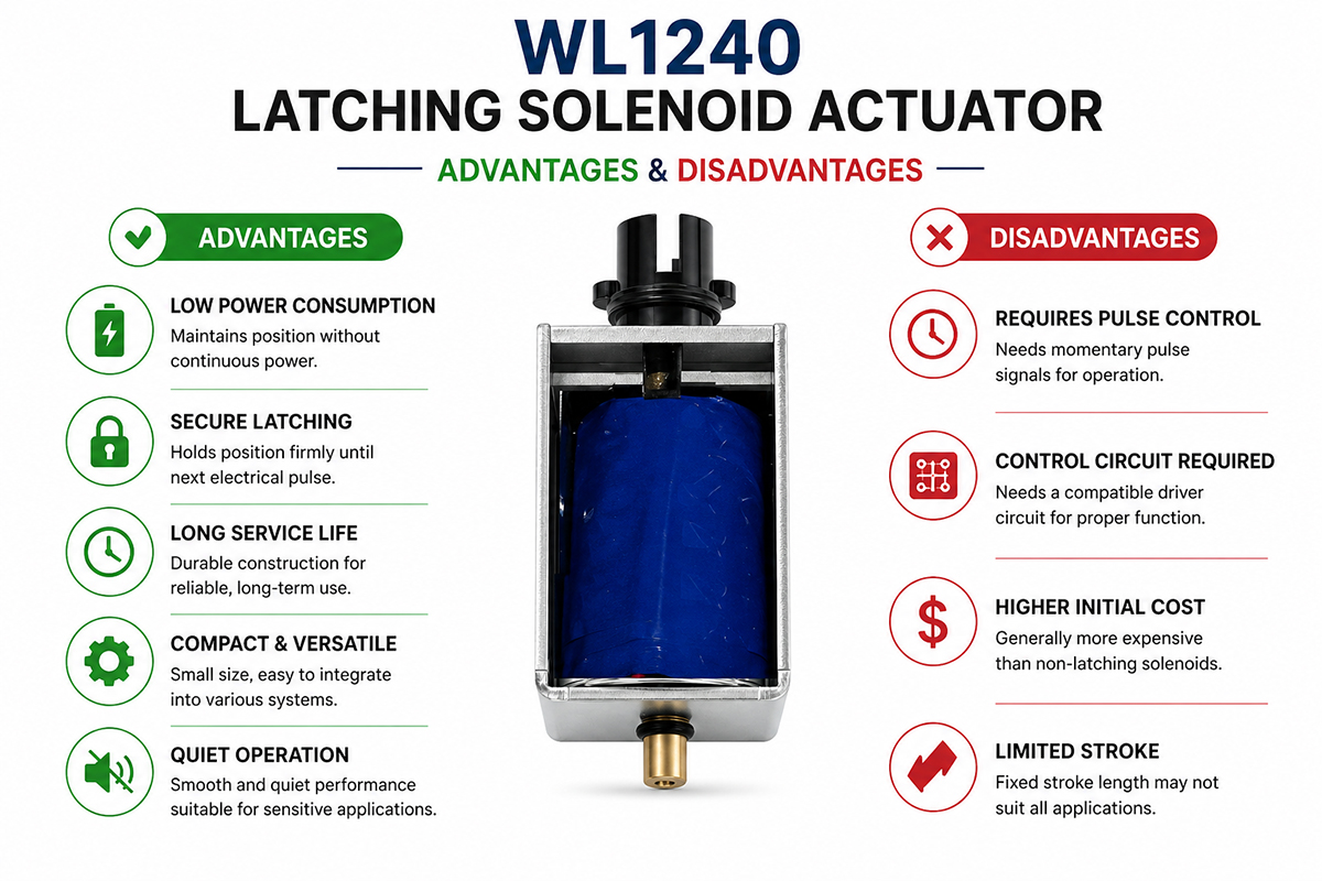
Advantages and Disadvantages of Latching Solenoids Actuator

Latching Solenoid Actuator advantage and disadvantage

Advantages of Latching Solenoids Actuator

No stand-by power. Main benefit of the actuator. Does not consume any power once locked into place.

Cool operation. Does not produce any heat while maintaining the current position, allowing use with plastics or inside enclosures.

Fail-safely retains the position in case of power outage. This makes them suitable for locks or valve shut-off devices.

Battery friendly. Suitable for portable and IoT devices.

Simple drive circuit. Can be operated with a drive circuit that uses capacitor discharge.

Compact designs. Latching actuators have strong holding force in relation to their size.

Disadvantages of Latching Solenoid Actuator

Bipolar drive. A reverse polarity pulse is needed to release the actuator, thus making an H-bridge required. Additional coils can solve this problem.

Low dynamic force. The locking mechanism decreases the force available for moving the plunger.

Demagnetization resistance. Can be affected by external magnetic fields and loses power in case of high temperatures.

Slow operation. Switching speed of 20-100 ms. Can be slower than other actuator types.

Limited stroke. Stroke is typically short (maximally 15 mm).

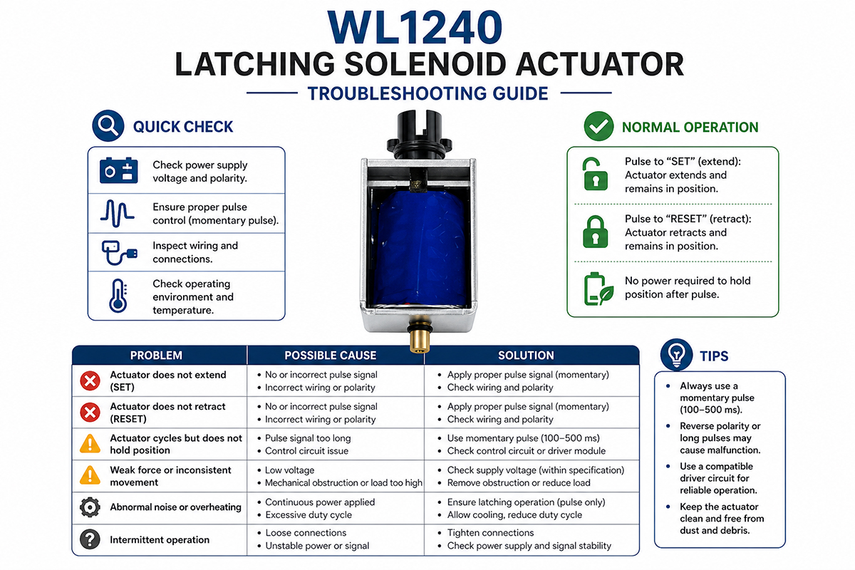
Fixing Latching Solenoid Actuator Symptom

Latching Solenoid Actuator Troubleshooting guide

1. Fails to latch/unlatch Problem(s):

– Insufficient voltage/current of the pulse.

– Short pulse width.

– Permanent magnet has worn out.

What to Do:

– Check supply voltage/current and use an oscilloscope to measure maximum current through the pulse.

– Lengthen pulse width (for example, make it around 100 ms).

– Confirm that drive can provide reverse polarity.

– Overheating (over 100°C) can result in the degradation of the magnet – in that case, replace the whole assembly.

Symptom 2. Weakly holds; the load pulls the plunger out Problem(s):

– Outside vibrations.

– Excessive operating temperatures causing demagnetization.

– Misalignment.

What to Do:

– Use a force gauge or another measuring technique to estimate how much holding force is there.

– Reduce the temperature or place heat shield around the assembly.

– Check whether the plunger fully reaches the end-stop – any dirt or uneven surfaces may prevent that.

– Choose a model with higher holding force.

Symptom 3. Stops and resumes working Problem(s):

– Loose wire connection.

– Contact oxidation inside H-bridge.

– Capacitive decay in circuit.

What to Do:

– Check all connections and re-seat them to pinpoint the faulty component.

– In the case of a capacitor discharge circuit, check the capacitance and equivalent series resistance (ESR).

– Driver transistors getting too hot may require replacement.

Symptom 4. Unpredictable behavior when put near other magnets. Problem(s):

– Interference from an outside magnetic field.

What to Do:

– Move away from sources of magnetic field or use magnetic shielding material (e.g., mu-metal).

– In the case of a persistent issue, increase pulse current.

Symptom 5. No sound/no plunger movement Problem(s):

– Coil wire breakage in open coil.

– Plunger doesn’t move due to rust/corrosion.

– Shorted drive circuit.

What to Do:

– Check for continuity and resistance of open coil, which should be within the range of 5 to 50 Ω (check the datasheet).

– Infinite resistance means the coil is dead.

– Apply some lubrication to the plunger using oil but avoid grease.

– Run test with a different source of electricity.


FAQs Of Latching Solenoid Actuator

Q1. Is it necessary for latching solenoid actuator to keep providing power?

– No. The permanent magnet ensures that the plunger stays in a given position after switching off the power supply. Only a short DC pulse of 20-100 ms is required to toggle latch positions.

Q2. Can I apply power using regular DC power supply?

No, a regular DC power supply produces continuous voltage, whereas latching solenoids require a bipolar pulsed supply to change positions. Dual-winding models will need an H-bridge drive or two separate coils to operate.


Q3. What will happen if there's a power outage during switching?

– The plunger might freeze in the middle of its stroke, but once switched to a new position and latched, it stops drawing current from the supply circuit. This makes latching solenoids useful for security lock systems or valves.

Q4. How much force will it produce?

Holding force will vary widely depending on size and will be somewhere between 1 and 100 N. The force when changing states is usually lower, around 30–50%—than non-latching solenoids with similar dimensions. You should consult the datasheet.

Q5. Can latching solenoid actuator get too hot like regular models?

Not usually. Since latching solenoids draw current only for a brief period (100 ms or less), they dissipate less heat and can safely operate even in plastic housing. Operating temperatures above 85°C may cause permanent magnet demagnetization.

Q6. How long will the permanent magnet remain magnetized?

Latching solenoids made by quality manufacturers feature neodymium or alnico magnets, retaining more than 90% of their strength even after decades of operation. Demagnetization can occur under extreme temperatures, exposure to strong magnetic fields, or physical shocks.

Q7. How many cycles can a latching actuator perform?

Industrial latching solenoid actuators are designed for 1 million to 10 million cycles. Magnet is almost never responsible for failures, and most wear occurs in the coil insulation and plunger guides. Frequent switching (above 10 Hz) will significantly reduce lifespan.

Q8. Which is better: push or pull actuator?

Push actuator – the plunger moves inwards when latching and can be used for opening the valve/switching the lock/lifting the lever. Pull actuator – the plunger moves outwards when latching and can be used for pulling the pin. Some models are symmetrical and can be used as push/pull actuators.

How to choose a latching solenoid actuator

The process of selection includes a thorough consideration of electrical and mechanical aspects.

1. Mechanical requirements.

First of all, you should define the required stroke length (typical values range from 2 to 15 mm) and force (holding or actuating force). Latching actuators are powerful when holding the load. That is why the actuator’s holding force must exceed any load exerted externally on it (due to spring, pressure, vibration, etc.). State whether a pulling or pushing force is needed.

2. Electrical drive.

Operating voltage typically ranges from 3 to 24 V DC. You should estimate the required pulse width (e.g., 50-150 ms) and peak current (e.g., 0.5-5 amperes). Moreover, it will need to generate bipolar pulses (reverse polarity) or use an H-bridge. For battery-operated devices, select the least possible holding force to minimize pulse energy (Joules = voltage × current × time).

3. Duty cycle and frequency of latching solenoid actuator

Latching actuators generate heat very rarely; however, they operate with specific limitations regarding the frequency, e.g., 1-10 Hz. In case of higher-frequency operation, you may need a regular solenoid.

4. Environmental conditions

Take account of temperature range limits; remember that magnets start losing power at temperatures above 80 degrees Celsius. Moreover, if humidity or dirt is expected, opt for sealed actuators with IP ratings. Note that some models tend to get triggered unintentionally under the effect of vibration; therefore, select actuators with strong magnetic detents if necessary.

5. Size and Mounting.

There is a wide range of shapes and sizes to select: tubular actuators are cylindrical and perfect for push/pull applications; box-frame is cheaper and smaller. Rotary actuators rotate 90 degrees and have shorter stokes. Also, specify required length, diameter, and mountings.

6. Safety considerations.

When choosing a latching solenoid as a lock system, consider its fail-safety, i.e., how it behaves in case of a power outage. Some of them do not have symmetrical designs; thus, it takes different pulses to lock or unlock the actuator. If required, check compliance with UL, CE, or RoHS certifications.

7. Supplier data.

Testing the actuator in your application is crucial; make sure that the supplier provides you with relevant data and force-stroke curves. Make use of the evaluation kit if you are going to test the product prototype.

Get A Free Quote Now

Contact Form

Related Products

Related News

Scroll to Top

Get A Free Quote Now !

Contact Form
If you have any questions, please do not hesitate to contact us.
Weilong Solenoid Company Culture
