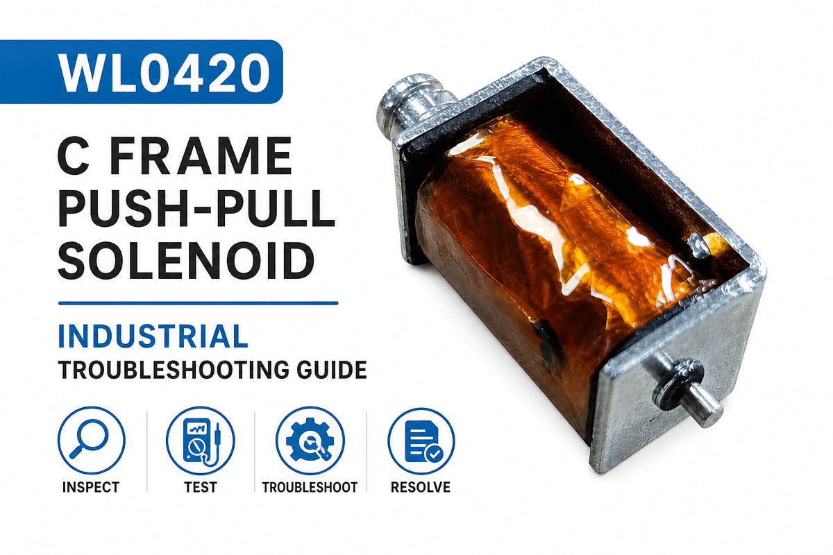
How to Choose a C-Frame Push-Pull Solenoid
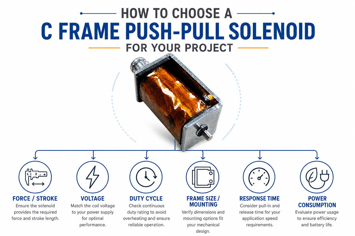
When choosing the right C Frame Push-Pull Solenoid, one should take into account not only the voltage but also the mechanical requirements first of all. Firstly, it is necessary to specify the type of the action: push, pull, release, lock, or position. Then measure the working stroke and determine the force needed at the beginning and the end of the stroke. The solenoid force depends on the plunger position, and the force value near the seated position should not be used as an example of the entire stroke.
Then one should determine the available power supply, including the rated voltage, the allowable current, the coil resistance, and the driving capacity. It is necessary to determine whether the solenoid will operate continuously or intermittently. The duty cycle is an important parameter because the temperature of the coil rises when it is energized. The device designed for short pulses may be overheated if it is left on continuously. One should also consider the ambient temperature, ventilation, other heat sources, and the allowed temperature of the finished product.
It is necessary to carefully consider the mechanical envelope, including body size, plunger diameter, the direction of the shaft, mounting holes, lead wire exit, connector position, return spring, and moving part clearance. One should avoid side loads, as misalignment increases friction, noise, wear, and the potential of sticking.
It is also necessary to evaluate the performance requirements, including the response time, operating noise, holding force, return force, cycle life, operating frequency, etc. In the case of smart appliances, the sound of impact is as important as electromagnetic force, and rubber stops or mechanical damping can be needed.
Finally, one should discuss the customization with the supplier, including drawings, voltage, stroke, force and position requirements, duty cycle, operating sequence, environment, annual quantity, and target life. Prototype testing should be done on the actual mechanism before the final design is confirmed. The validation should be done with the worst-case voltage, temperature, load, tolerance, and repeated cycling.
If the mechanism has to be energized for long periods, the continuous duty options should be compared. If the movement is the only purpose, then the pulse operation can reduce the heating and the power consumption as well as the coil size without changing the actuation force.
How to Prevent Typical Errors During Designing a C-Frame Push-Pull Solenoid?
1. Don’t choose the solenoid on rated voltage alone.
The voltage is just one parameter. Stroke, force, duty cycle, temperature, current, mounting space, return spring, and operating life are also important.
2. Don’t treat the holding force as the necessary initial force.
Solenoids provide maximum force near the seated position of the plunger. The force at the maximum stroke can be much lower.
3. Keep the stroke to a minimum.
An increasing air gap decreases the electromagnetic force. Make the required stroke as short as possible.
4. Determine the actual duty cycle.
A coil designed for short duty may become too hot if it is energized for too long.
5. Take into consideration the tolerance of the supply voltage.
Test the actuator at minimum and maximum voltage, including the voltage drop through wiring and the driver circuit.
6. Don’t side-load the plunger.
The shaft should be in its intended axis. Side loading causes friction, noise, wear, and sticking.
7. Don’t use the return spring, which is too strong.
The solenoid must overcome the spring force and external mechanical load.
8. Provide sufficient mechanical clearance.
Consider the manufacturing tolerances, thermal expansion, assembly variations, and wear.
9. Provide coil protection in the driver circuit.
When the inductive load is switched off, it generates a voltage transient. Include appropriate flyback or transient suppression.
10. Think about the operating noise.
High-speed plunger impact may produce clicks. The quiet appliance may need mechanical stops, damping material, reduced impact velocity, or controlled current.
11. Shield open-frame design from contamination.
The plunger movement can be blocked by dust, moisture, grease, fibers, and other foreign particles.
12. Look inside the finished product.
The bench performance doesn’t always mean the final performance. Test the actual assembly with the real voltage, temperature, load, tolerance, and expected cycle life.