

Chapter 1: Introduction of Solenoid Lifespan?
The solenoid lifespan represents one of the most widely considered points nowadays in automation systems. The main function of a solenoid is to convert electrical energy into linear mechanical action. This device has many uses, from industrial valves and automation lines to medical devices.
However, one of the important parameters for any engineering product is solenoid lifespan measured in cycles of operation. When choosing such a product as the solenoid with a long lifetime, we talk about either 100,000 cycles of operation or one million cycles.
A solenoid lifespan with 100,000 cycles may be sufficient in light-duty applications. However, the solenoid lifespan of 1,000,000 solenoids has become a must-have feature in industrial automation and high-volume production systems. It’s possible only due to superior thermal performance, superior mechanical design, and superior materials.
Product engineers and designers need to take it into account because:
They are connected to maintenance costs
Failures mean downtime
Impact system reliability
The total life-cycle cost
In this article, we will cover everything that relates to this subject in detail, starting with the basics and going deep into practicalities and tips.
Chapter 2: How long does a solenoid’s lifespan last?
The solenoid lifespan is the number of on/off switching cycles the solenoid is capable of making without performance degradation.
Usually, one cycle involves:
Powering the coil up
Plunger movement
Restoration of initial state
But failure of the solenoid does not necessarily mean a total breakdown but rather the following signs:
Reduction of force generation capability
Slow response time
Excessively heated
Increased mechanical wear
Coil insulation deterioration
In the industry, it is important not only the maximal peak of force generation but also a stable lifetime of the solenoid.
Chapter 3: Comparing solenoid lifespan: 100,000 vs 1,000,000 Cycles
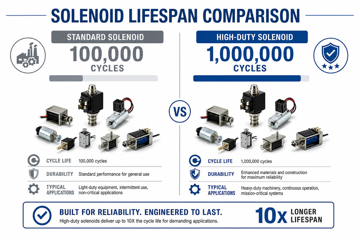
3.1 100,000 solenoid lifespan
A solenoid that can sustain 100,000 cycles is used in:
Light-to-medium duty systems
Occasional-use systems
Applications where price matters
Engineering Characteristics
Copper wound coil
Standard insulation for Class B or Class F
Mechanical return spring
Problems
Low heat dissipation capabilities
Lower grade of magnetic steel
Advantages
Cheaper price tag
Quick and easy manufacturing
Sufficient for non-critical applications
3.2 1 Million solenoid lifespan
This type of solenoid is intended to work in industrial environments and have a long operational lifetime.
Design enhancements
Good quality copper wire with better insulation (enamel of Class F or Class H)
Improved insulation systems (Class F or Class H)
Precision machining of the plunger and housing
Improved Air gap
Better heat management (with heat sinks or thermal paths through housing)
Low-friction materials
Pros
Higher dependability
Operates for a long time
Continuous good performance
Lower maintenance cost
Drawbacks
Higher up-front cost
Increased production complexity
Main Applications
Industry automation system
Automotive actuators
Medical instruments
Packaging equipment
Duty continuous equipment
3.3 Main Engineering Differences
Characteristic 100k cycle, 1m cycle
Coil QualityStandardHigh-grade
Heat Resistance: Low/High
Life Span Capacity Limited/Unlimited
Total Cost of Ownership Higher Lower
Chapter 4: Solenoid Working Principle
How does a solenoid operate? It utilizes electromagnetic force.
An electrical current in the coils generates the magnetic field. The magnetic field creates a force acting either on a ferromagnetic plunger pushing it inward or pulling it outward, thus creating linear motion.
The basic formula of the force produced by an electromagnet is:
F = B I L sin θ
Where:
F = force generated
B = magnetic flux density
I = current
L = length of conductor in the magnetic field
θ = angle between current and magnetic field
Basic working procedures
Energization of the coil with electricity
Immediately, magnetic field is created
Pull/Push of the plunger
Mechanical action does work
De-energization and mechanical spring returning the plunger
Due to high reliability, solenoids are used in automated systems widely.
Chapter 5: Effect of Internal Solenoid Construction on solenoid lifespan
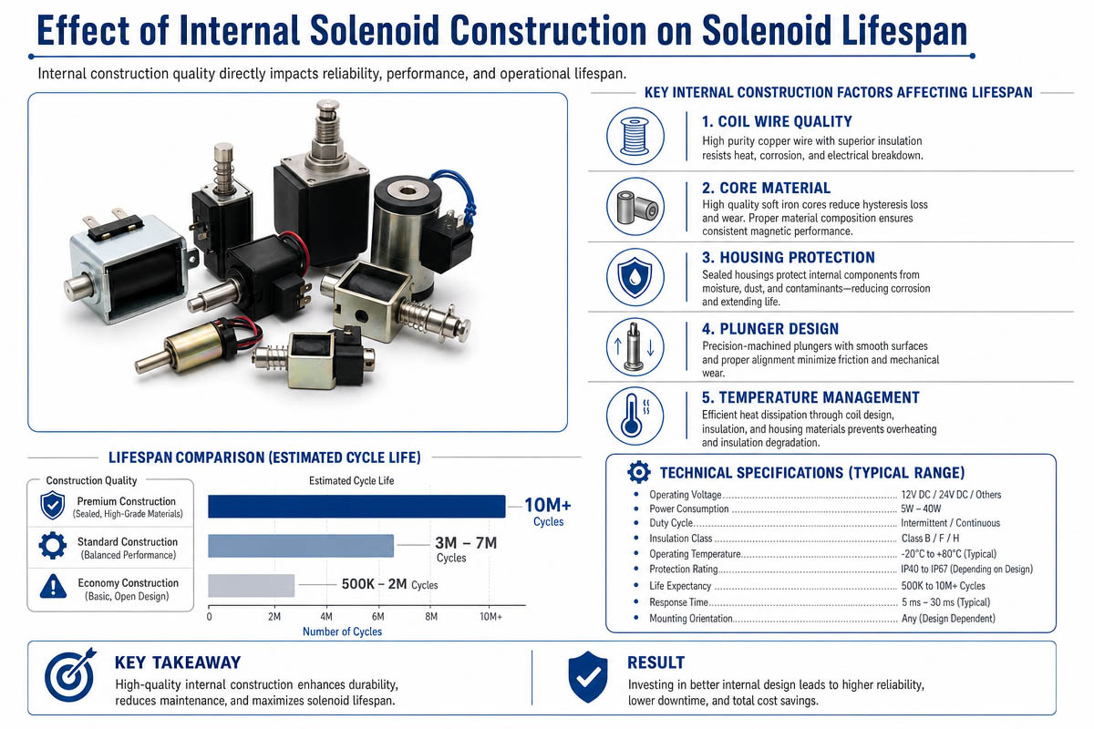
5.1 Coil Design: #1 Parameter to Consider
The coil is the ‘engine’ of the solenoid actuator. The design determines the heat output, the insulation stress, and the magnetic efficiency.
Consequences on the solenoid lifetime
Bad quality of coil winding -> bad current distribution -> overheating
Cycling damages low-grade insulation of enamelled wire
High-resistance design = excessive heating during each cycle = aging faster
solenoid lifespan 100,000 cycles
Cheap copper wire.
Low-grade insulation class (class B or F)
Poor heat dissipation capability
solenoid lifespan 1 million cycles
High-quality copper wire (Class F or Class H Insulation)
Optimized winding density
Efficient heat dissipation pathway
Key point: The coil overheating is the major contributor to the short lifespan in 80% of cases.
5.2 Plunger (Armature) Wear During High Cycle Usage
The plunger is a moving part. Its design determines the mechanical durability.
Impact on the solenoid’s lifespan
Rough surface -> wear -> jamming failure
Misalignment -> lateral force -> uneven wear
Low-grade magnetic steel -> deformation during cycling
Solenoid wear mechanisms
In each cycle, we get:
Impact force
Kinetic friction
Magnetic pull force
That leads to:
Stroke inefficiency increases.
Delayed response time
Sticking
Improvements to increase solenoid life
Plunger surface grinding (low roughness)
Anti-wear coatings
Optimized clearance of the plunger in the tube
5.3 Magnetic Core & Housing: Heat Management & Effic
The magnetic core is responsible for efficient force production.
Factors that impact the longevity
Low-quality magnetic core steel -> increased heating -> high current needs
Bad core geometry -> inefficient force generation -> long energization times
Suboptimal housing design -> bad heat dissipation capability
Main structural problems with low-end solenoids
Early magnetic saturation
Energy losses per each cycle increase
Temperatures rise
Enhancements to increase life-time
High-permeability magnetic core
Improved design of the magnetic circuit
Heat-conductive housing materials
More magnetic efficiency = fewer heat losses = longer solenoid lifetime.
5.4 Solenoid Return Spring: Fatigue Cycles
The spring determines cycle stability and the ability to return the plunger.
Factors that affect the solenoid life
Spring fatigue reduces the force -> incomplete return stroke of the plunger
Reduced elasticity -> delay in returning the plunger
Wear on the spring lower then the friction force
Main failure modes at high cycling
Weakening of the spring
Incomplete plunger resetting
Misalignment of the solenoid due to wear
High life-span improvements
High fatigue-resistant steel springs
Optimized compression ratio
Optimal stress range
5.5 Electrical solenoid lifespan Limitation of Insulation System
The insulation of the wires determines the thermal limit of the solenoid’s operation.
Factors influencing the solenoid lifespan
Heating plus voltage stress -> insulation failure -> short circuit -> sudden failure
Ageing of the insulation -> reduced efficiency -> overheating
Solenoid design with low lifetime
Standard insulation (Class B)
Temperature tolerance ~ 130 °C
Solenoid with prolonged life
Class F (temperature tolerance 155°C) or Class H (180°C)
Impregnated varnished wires
Epoxy-coated under vacuum process
Insulation aging is often the ‘silent killer’ of solenoid lifespan.
5.6 Air Gap and Tolerance of Mechanisms: Efficiency & Heat
The air gap between plunger and coil determines the efficiency of magnetic force generation.
Effects on the solenoid lifetime
Air gap too big -> too much current needed -> increased heating
Too narrow -> friction -> mechanical wear and failure
Too loose tolerance -> unstable force generation
Design flaws in solenoids with short lifetimes
Large tolerance limits
Irregular plunger stroke pressure
Extra losses of energy per cycle
Best practices of designing
Machining with high precision
Optimized controlled air gap
Improved balance of force and friction.
5.7 Thermal Dissipation Path Design
Solenoids operate better if they are cooled. Thermal pathways are determined by its design.
Design flaws
Hot spot of the coil -> inability to dissipate -> quick spreading
Insulated coil -> no heat transfer
The heat dissipation path is ineffective
Optimal design
Metal housing serves as a heat sink
Optimized coil positioning for heat dissipation
Better heat transfer through the use of special grease/epoxy
Even a 10°C reduction can increase the solenoid lifetime dramatically.
Conclusion: Structural Effects on Solenoid Life Time
Solenoid Component Design Flaws Impact High-quality Design Benefits
Coil Overheating, insulation damage, thermo-stability
Plunger Jamming, wear Smooth operation
Magnetic core: high heat generation, losses Efficient force production
Return spring Fatigue, incomplete stroke cycle Stable stroke cycle
Insulation Insulation breakdown, heating. Heat resistance
Thermal pathway Losses Efficiency, thermal dissipation
Heat loss, heat build-up Efficient thermal pathway
Final Engineering Insights
Solenoid failure cannot be attributed to one single component because it is caused by insufficient performance of the system as a whole.
High heat generation from subpar coil
Heat speeds up ageing of insulation
Increased wear increases friction
More current demands per cycle
Heating of the solenoid increases again
That’s a failure cycle.
The cycle is stopped by using a 1 million-cycle solenoid:
Improved thermal characteristics
High-grade insulation
Precision mechanical engineering
Minimal energy loss per cycle
Chapter 6: Solenoid Applications in Different Fields
Solenoids are essential components due to fast response and reliable operation.
6.1 Industrial Automation
Industrial pneumatics control systems
Robots
Assembly Line Systems
Package equipment.
6.2 Automotive industry
Injection systems
Transmissions
Automobile door actuators
Emission Control System
6.3 Medical applications
Control valves for liquids
Medical diagnostic systems
Laboratory automation.
6.4 Consumer Electronics & Appliances
Washing machine
Automatic coffee maker
Security locks for your home.
The required lifetime of the solenoid depends on the application.
Chapter 7: Common Mistakes affect the solenoid lifespan and Their Fixes in Selecting the Right Solenoid
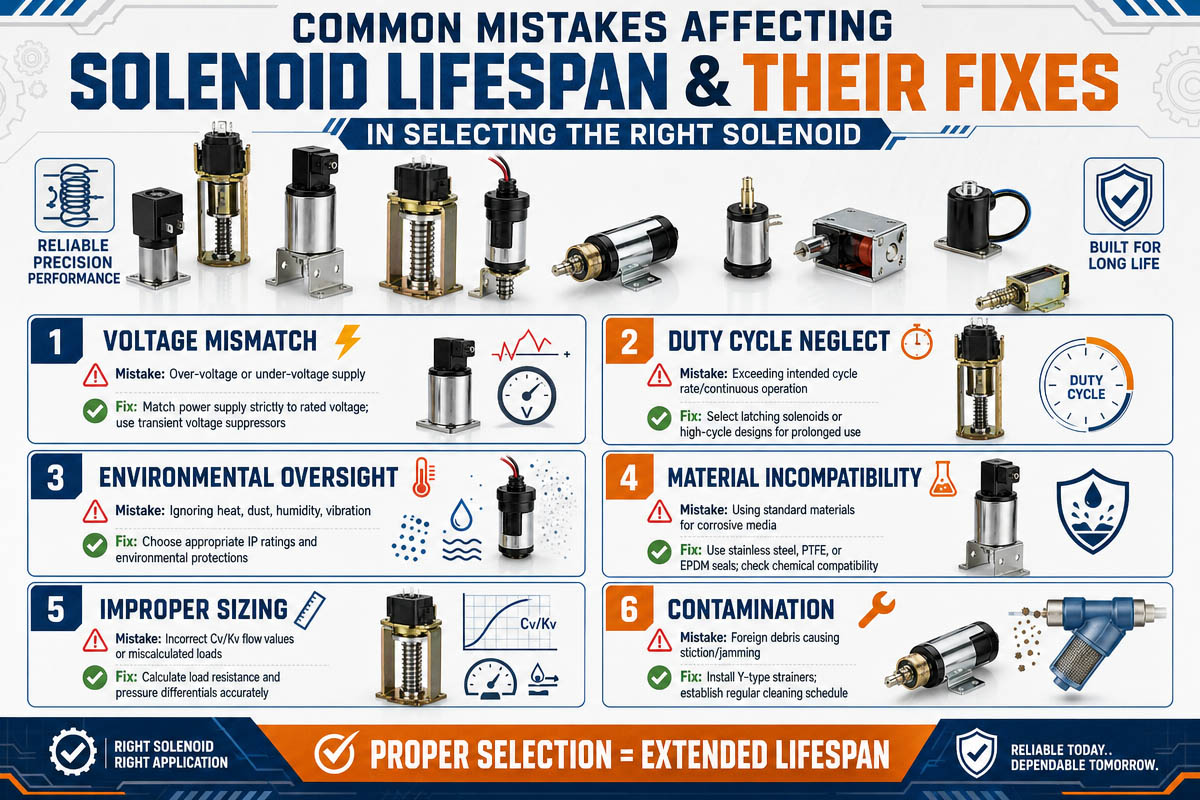
Selecting a wrong type of solenoid will definitely cost you more. The following is a list of the most common mistakes and ways to avoid them.
Mistake #1 – Neglecting Duty Cycle
The Problem
It is common to select a solenoid based on force or voltage, but not on duty cycle. For instance, a solenoid with a 10% duty cycle will quickly overheat if run at 50%.
The Harm It Will Do
Heat is one of the leading causes of failures in solenoids. Exceeding the duty cycle results in insulation failure, coil burnout, and other problems within days or weeks.
Ways to Prevent This
Calculate your duty cycle: Duty Cycle = (Time Energized / Total Cycle Time) x 100%. Leave 20% overhead and, if you have 100% duty, either use a solenoid designed for it or employ PWM to reduce the power applied. General rule: over-specify the duty cycle.
Mistake #2 – Judging Solely on Force
The Problem
Solomonids with the same force rating do not guarantee the same lifespan, thermal performance, and durability.
The Problematic Outcome
A cheap solenoid with the same force rating can fail from overheating, wear, or old insulation, while another more expensive model may operate efficiently for years.
Evaluate solenoids on these additional criteria:
| Criteria | Why It Matters |
| Lifespan rating | 100K vs 1M cycles directly impacts replacement frequency |
| Insulation class | Class B (130°C), F (155°C), or H (180°C) determines thermal headroom |
| Thermal design | Does the housing act as a heat sink? Is there a thermal path? |
| Mechanical precision | Tolerances affect wear, noise, and long-term consistency |
Key insight: The cheapest solenoid by price is often the most expensive by total cost of ownership.
Mistake #3 – Opting for Cheap Model
The Problem
Cheaper solenoids usually feature simple windings, lower quality insulation, a simpler spring, and wider tolerances. They are suited for occasional and non-critical uses only.
The Harm It Will Do
– More costly labor of replacement
– Difficult tuning process due to inconsistent performance
– Potential risk for damaging surrounding hardware
How to Avoid This common mistake that affect solenoid lifespan
| Application Criticality | Recommended Solenoid Grade |
| Non-critical, low-cycle | 100K cycle, basic insulation |
| Moderate duty, occasional failure acceptable | 250K–500K cycle, Class F |
| Critical, high-cycle, zero unplanned downtime | 1M+ cycle, Class H, precision mechanics |
Mistake #4 – Choosing Wrong Voltage
The Problem
Applying a 12V-rated solenoid at 24V (or vice versa).
The Problematic Outcome
If you use too much voltage, then the current and hence the power increase, respectively; it raises the temperature and burns out your solenoid very fast. Too little will result in incomplete seating, overheating, and reduced current and force.
How to Avoid This
– Ensure match between supply voltage and nominal ±5%
– Consider the loss on long wiring by using thicker wire or higher rating
– Use wide range option for battery and unregulated voltages (i.e., 10-15V for 12V nominal)
– Measure voltage directly across the solenoid connections before connecting
Mistake #5 – Not Taking Mechanical Loads into Account
The Problem
Judging by the rated force, not the actual one including side loads, friction, and impacts.
The Harm It Will Do
– High overload decreases the number of cycles by 50-90%
– Uneven side loading and jamming
– Return spring and end stop damage from impacts
Prevent It by
Measuring or calculating peak mechanical load (not average) and
– Applying the 1.5-2x safety factor
– Ensuring axial load (using guides, if necessary)
– For high-cycle applications, derate force by 20-30% throughout time
– For example, if you need 5N force, buy 8-10N solenoid
Mistake #6 – Poor Thermal Design
The Problem
Not taking care of the heat dissipation. Otherwise your solenoid will fail.
The Problematic Outcome
Insulation lifespan reduces twofold with each 10-degree temperature increase (according to Arrhenius). The excess heat will result in local heating and affect adjacent devices.
How to Avoid it and make longer Solenoid Lifespan
| Thermal Solution | Effectiveness | Complexity |
| Free air (no cooling) | Low | None |
| Metal chassis mount | Medium | Low |
| Heat sink | Medium-High | Low |
| Forced airflow (fan) | High | Medium |
| PWM control | High | Medium |
| Liquid cooling | Very High | High (rarely needed) |
Mistake #7 – Failure To Consider the Working Environment
The Problem
Using standard solenoid in harsh environments (dust, humidity, vibration, corrosives)
The Problematic Outcome
– Debris and dust will block it and increase wear
– Humidity will lead to corrosion and insulation degradation
– Vibration loosens all connections and speeds up fatigue
– Corrosion affects insulation and metallic parts
Prevent It By
Picking an appropriate IP rating: IP40 (only dry air); IP54 (protects against dust and splash); IP67 (protection against dust and submersion).
Choose a sealed/encapsulated unit for washdown and outdoor environments.
In a vibrational environment: use locking connectors and thread-locking compounds.
For corrosive environments: use stainless steel or coated housing.
Mistake #8 – Not Testing Under Actual Conditions
The Problem
Bench tests will never replicate real-life thermal buildup, wear effects, and intermittent performance issues.
The Problematic Outcome
Such problems can be seen only after thousands of cycles performed at elevated temperatures
Prevent It By
Building a test fixture resembling your real-life conditions.
Performing accelerated life tests under constant temperature monitoring.
Testing at maximal possible ambient temperature.
Monitor force, response speed, and power drawn at each 10kth cycle.
For critical applications, test 1.5x the required number of cycles.
Rapid Solenoid Selection Checklist
Prior to selecting, check for the following:
– Duty cycle with 20% overhead
– Required force with 1.5-2x safety margin
– Matching voltage to the supply ±5%
– Thermal management implemented
– Proper environmental protection selected
– Lifetime comparable with the maintenance program
– Adequate insulation class with regard to temperature
– Axial mechanical load within limits
– Actual performance tested
Chapter 8: Increasing the solenoid lifespan
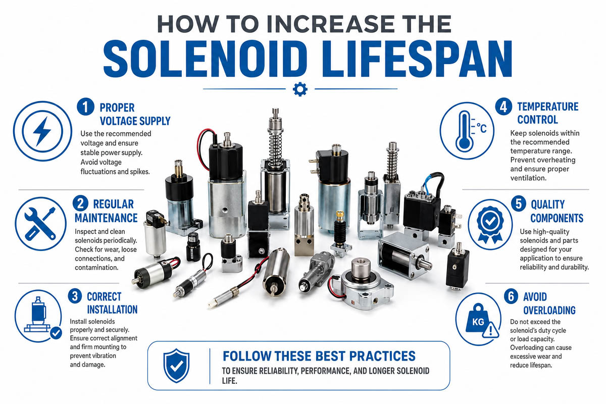
If engineers wish to improve the performance of a solenoid, three directions should be considered: electrical, thermal, and mechanical.
Electrical optimization
Using Pulse Width Modulation (PWM) control instead of continuous current
Protection against voltage spikes
Shaping the current waveform
Thermal regulation
Using heatsinks
Optimal air-flow design
Better heat dissipation through housing
Optimizing mechanics
Minimize friction of plunger movement
Precise mechanics
Applying anti-wear coatings
Materials Choice
High-grade insulation classes (F or H)
High-grade copper wire
Magnetic steel
Chapter 9: FAQs on Solenoid lifespan
Q1: What is the actual meaning of ‘solenoid lifespan’?
A ‘solenoid lifetime’ refers to the maximum number of full cycles of action (ON / OFF) that the solenoid is capable of performing till its operational capacity becomes below an acceptable level.
Q2: Why do 100k solenoids get worn off faster than 1 million solenoid lifespans?
This is mainly due to the difference in materials used in each of these solenoids. They have lower insulation and materials with poor thermal resistance capabilities and thus cannot sustain prolonged action.
Q3: Is there such a thing as a million-cycle solenoid lifespan?
Yes, industrial solenoids can go up to 1 million cycles and sometimes even more. This is made possible by having precise machining, high-grade wire, Class F or Class H insulation, and heat-resistant properties.
Q4: What is the single most important determinant of a solenoid lifespan?
The key here is heat generation, which reduces insulation capacity, increases electrical resistance, and weakens magnetism of the solenoid. Electrical and mechanical stress also plays a major role.
Q5: What happens with the solenoid lifespan with respect to duty cycle?
It depends directly on heat generation; the more time spent on energizing, the greater the heat and thus the reduced lifetime of the solenoid. Do not forget to choose the right type based on your particular application and its duty cycle.
Q6: Can I somehow prolong the solenoid lifespan?
Yes, but only to some extent because solenoids are designed with a certain duty cycle limit in mind. The ways to do so include:
Decreasing voltage level or using pulse width modulation
Improving heat dissipation
Reducing mechanical friction and load
Avoiding voltage spikes
These actions cannot completely resolve the problem; therefore, if you need an efficient long-time solution, buy solenoids with a high cycle rate from the beginning.
Q7: So, I have two solenoids—100K and 1M cycles each—and want to choose the best one. Which one is better?
Consider the following factors:
Amount of cycles per day/week (continuous usage will require 1 million solenoid);
Possible costs of shutting down equipment due to failures (high cycle rating would be more preferable);
Environmental conditions (if they are difficult, then use rugged solenoids);
Overall cost of operation and maintenance.
Q8: How do you determine that your solenoid is nearing the end of its operational solenoid lifespan?
This can be easily noticed due to such problems as
Decreased speed of motion;
Lower force exertion;
Unusual noises and vibrations;
Increased temperature level during operation;
Failures in operation and resetting.
If these signs appear, consider checking its electrical parameters, physical state, and insulation capabilities to avoid total breakdown.
Chapter 10: Troubleshooting of Common Problems With Solenoids That Affect Solenoid Lifespan
common problems, their typical causes, and practical solutions.
| Problem | Common Causes | Troubleshooting Steps | Preventive Solutions |
| 1. Overheating | – Over-voltage – Duty cycle too high – Poor heat dissipation – Coil partial short |
– Measure supply voltage – Check actual duty cycle vs rating – Feel housing temperature during operation |
– Reduce voltage or use PWM control – Add heat sinks or forced airflow – Upgrade to higher insulation class (F or H) |
| 2. Weak or Inconsistent Force | – Coil degradation – Low supply current – Plunger wear or misalignment – Voltage drop in wiring |
– Measure coil resistance (compare to spec) – Check power supply stability – Inspect plunger for wear or debris |
– Replace degraded coil – Use thicker gauge wiring – Clean and lubricate plunger path – Implement voltage regulation |
| 3. No Movement (Dead Solenoid) | – Broken coil (open circuit) – Mechanical jam – No power to coil – Burnt insulation (short circuit) |
– Check continuity with multimeter – Manually move plunger to feel for binding – Verify power at coil terminals |
– Replace solenoid if coil is open/short – Remove debris or realign assembly – Add overcurrent protection (fuse/PTC) |
| 4. Short Lifespan (Premature Failure) | – Excess mechanical friction – Poor thermal design – Incorrect voltage or duty cycle – Low-grade materials |
– Inspect plunger and guide tube for scoring – Log cycle count vs temperature rise – Review application specs vs solenoid rating |
– Improve alignment and lubrication – Reduce heat via cooling or PWM – Upgrade to 1M-cycle industrial solenoid |
| 5. Noise or Vibration | – Loose mounting or components – Magnetic circuit imbalance – AC solenoid chattering (if AC powered) – Plunger not fully seating |
– Tighten mounting screws – Check for bent plunger or core – For AC: verify shading ring is intact – Listen for rhythmic buzzing vs random noise |
– Use rubber grommets or lock washers – Replace damaged shading ring (AC only) – Ensure full stroke without obstruction |
| 6. Slow Response (Delayed Actuation or Release) | – Residual magnetism – Contaminated air gap – Weak return spring – Voltage ramp-up too slow |
– Check if plunger sticks in energized position – Clean plunger and core faces – Compare spring force to original spec |
– Use non-magnetic coating on plunger tip – Filter compressed air (if pneumatic) – Replace spring proactively at half of rated life |
| 7. Intermittent Operation | – Loose electrical connection – Worn or pitted contacts (if relay-driven) – Thermal intermittent (cools then works again) – Vibration causing momentary opens |
– Wiggle wires while monitoring continuity – Inspect control relay or driver circuit – Monitor temperature at failure moment |
– Crimp or solder all connections – Use sealed or automotive-grade relays – Reduce ambient temperature or cycle rate |
| 8. Coil Burnout (Visible Damage) | – Continuous over-voltage – Duty cycle exceeded for long period – Short circuit between winding turns – Contamination (oil, water) penetrating insulation |
– Smell for burnt odor; inspect for discoloration – Compare applied voltage to rated voltage – Check for moisture ingress |
– Install voltage clamp or regulator – Always derate duty cycle by 20% minimum – Use conformal-coated or encapsulated coils |
Chapter 11: Solenoid lifespan Conclusion
A 100,000-cycle solenoid differs considerably from a 1 million-cycle solenoid in terms of engineering, materials used, and mechanical properties.
The selection of the latter is a sign of a wise approach towards the choice of components. A 1 million cycle solenoid helps to ensure higher reliability and decreased downtime of equipment.


