

Chapter 1:Introduction of Automotive Metal Stamping
Automotive metal stamping plays a very important role in the manufacturing of automobiles. All the Automotive metal staming parts from body panels, to brackets, reinforcement plates, battery covers, and chassis components must comply with rigorous safety and aesthetic criteria. Quality and durability of stamping dies guarantee success of the stamping process throughout all stages of its implementation from prototype manufacturing to mass production.
Despite advances in CAE simulation and new developments in materials science, many businesses remain entangled in an expensive, time-consuming loop of Tryout -> Die modification -> Re-tryout -> Adjustment. Each change increases costs for tooling, prolongs project development cycle, puts a strain on engineering capacity and reduces overall efficiency. In extreme cases, development process takes several months which directly impacts the schedule of launching a new automobile model.
In this article we summarize practical recommendations from decades of working in automotive stamping facilities and die shops. It reflects a whole lifecycle of a stamping die from layout and CAE simulations through die tryout, optimization and mass production. Following the tips in this guide allows to significantly improve chances for success in stamping projects.
Chapter 2:why the Automotive Metal Stamping is Importance
Modern automobile manufacturers are increasingly relying on advanced materials to meet their fuel economy and safety needs. Those materials are:
High Strength Steel (HSS)
Advanced high strength steels (AHSS)
Stainless steel
Aluminum alloys (5xxx and 6xxx series)
Such advanced materials allow to achieve excellent structure and lightness but present manufacturing difficulties in the following aspects:
Deep drawing – high draw ratios
Springback control – control of material instability after formation
Prevent cracks from splitting
Control wrinkling – control of compressive instabilities
- Resistance to tool wear – long die life with high contact pressures
Thus, successful automotive metal stamping requires balance between:
✔ Design Skills – proper strip layout, forming and draw bead designs are critical for decreasing defects and achieving dimensional accuracy.
✔ CAE Simulation – sophisticated simulation programs like AutoForm, DYNAFORM or PAM-STAMP allow to predict thinning, material flow, wrinkling, cracking and springback before the die tryout.
✔ Tryout – ultimate success depends on adjustments related to draw beads, nitrogen pressure, shims, inserts etc. No software can replace expert knowledge.
Chapter 3;Common Issues of Automotive Metal Stamping
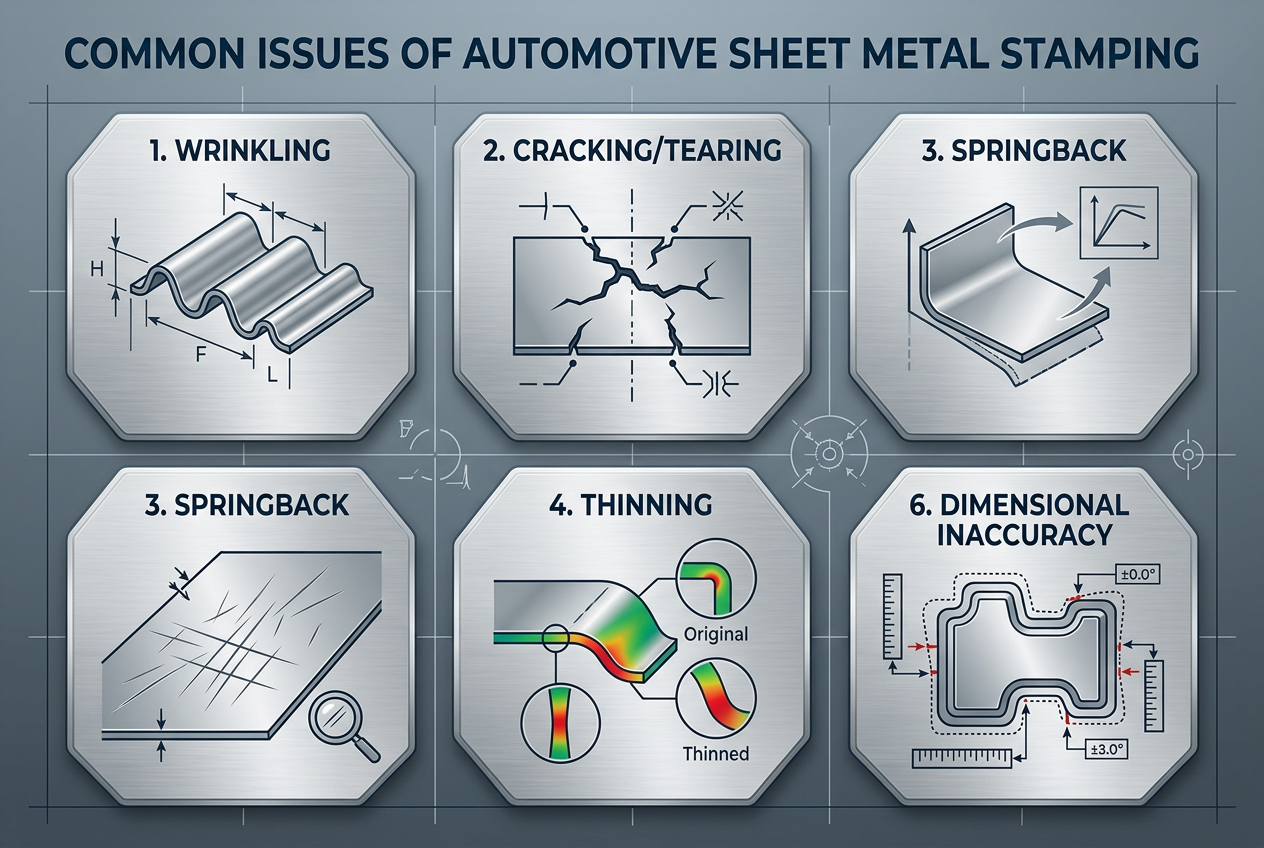
3.1 Wrinkle
Causes may include:
Insufficient blankholder pressure
Bad or worn out draw beads.
Unbalanced forming of material flow
Incorrect blank dimensions
Solutions:
Increase blankholder pressure or install deeper draw beads to increase restraining force
Modify geometry of draw beads (height, width, location)
Improve blank layout to regulate material flow
Additional embosses or restraining areas
3.2 Cracking
Reasons:
Excessive thinning beyond the material limits
Too small corners leading to stress concentration
Incorrect punch or form dimensions
Inefficient lubrication or improper material properties
Solutions:
Increase punch radius R. Add additional preforming steps
Increase blank size to avoid stretching
Intermediate annealing (especially for stainless steel and AHSS)
Optimize draw beads
Over spring-back
3.3 Remedies:
Bending correction at die surfaces
Restraint features e.g., ribs
Additional restrike operations
CAE based springback correction
increase blankholder forces or draw beads to induce additional plastic deformations
Chapter 4: Automotive Metal Stamping Design Stage: Establishing Solid
Foundations
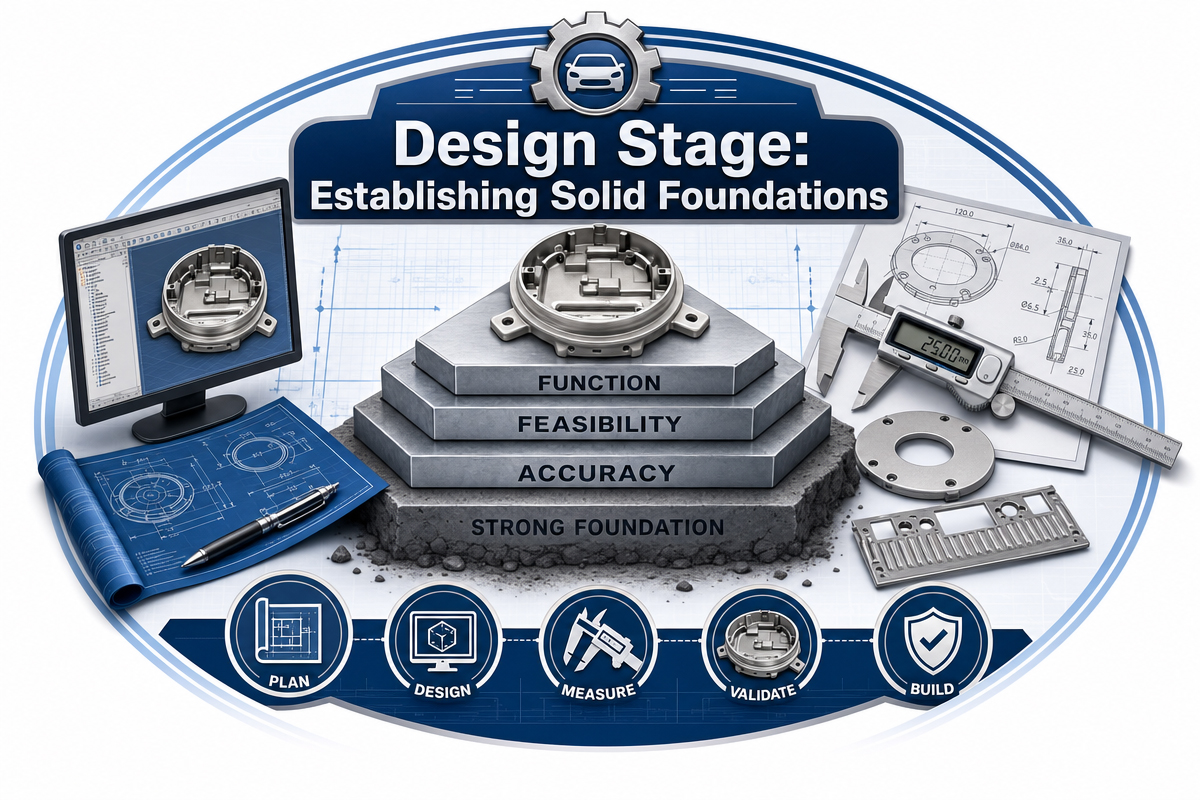
Design tip 1: Process analysis before die design
Before commencing work in CAD software conduct comprehensive process evaluation. Calculate minimal draw ratio, flange length, hole edge distance and material properties. Compare to benchmark data for similar stamping operation. Identify problem areas at preliminary stage.
Design tip 2: Strip layout and CAE evaluation –
The strip layout defines stamping process sequence. Always perform CAE simulation using the full strip model. Predict material distribution, pilot holes and carrier strip strength. Compare thinning prediction with historical values.
Design tip 3: Empty stations
Never fill all stations of your strip with forming operations. Insert empty stations into the process so that future adjustments could be made without dismantling the entire die. Empty stations also provide places for installing sensor, scrap drop-off and secondary tools.
Design tip 4: Lifter design
Reliable lifters are crucial elements of progressive stamping dies. Employ lifter with adequate force and stroke to clear all formed features. Never use small lifters with insufficient spring power. Make sure they have clearance for transferring to next station on feed line.
Design tip 5: Die material selection and surface finishing
Match materials to production volumes. Cast iron or hardened steel could be enough for limited batch production of prototypes. Premium steels such as DC53, 1.2379 or powdered steels used for high-volume stamping of AHSS. Finishing includes PVD coating, TD surface treatment or nitriding.
Design tip 6: Inserts
Make critical surfaces of forming inserts interchangeable. Using inserts allows fast die adjustments with shims or grinding. Just changing inserts will save 30%-50% time needed for die adjustment. Moreover, inserts eliminate scrapping of entire die faces during adjustment process.
Tryout Stage: Polishing Your Die
Design tip 7: Nitrogen springs –
Nitrogen springs should be used with care. Excessively high pressure is detrimental for your tooling. Use only amount necessary to complete task and record exact values in tool log book. Too high pressure accelerates die wear and possibly causes cracks.
Design tip 8: Precautions for first tryout –
Start die trials with lowest possible press speeds and nitrogen pressure. Set limit switches or mechanical stop to prevent overtravel. Carefully watch each operation at low speeds and listen for unusual noise. Even a small mistake at high speed kills the die within seconds.
Design tip 9: Red Lead Inspection Test
Red lead (or machinist’s blue) contact test is fast and reliable way to check contact areas of dies. Apply a thin layer of red lead to punch, close the dies under high pressure and observe transfer to the die block. Try to establish contact on 70-80% of forming surface. Sharp edges indicate potential stress raiser.
Design tip 10: CMM measuring criteria
Prior to the first tryout procedure create written protocol for coordinate measuring machines (CMM). Determine dimensions, number of pieces per measurement cycle and tolerances. Measure pieces in unrestrained and constrained conditions simulating future assembly. Measurement results are then compared against CAE springback prediction.
Design tip 11: Sample validation for client
Do not wait until die performs perfectly. Send samples to your client early for validation of priorities. Sometimes a small sample is enough for agreement on priorities and future action plan.
Chapter 5: Automotive Metal Stamping Special Forming Technology and Materials
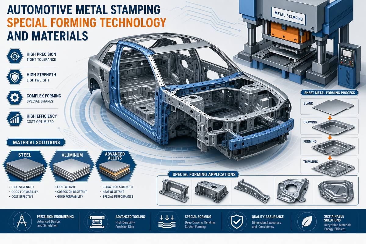
Design tip 12: Automotive metal stamping of AHSS (advanced high strength steel)
AHSS is quite different from regular steel. Main differences are in large bending radii, higher clearance between dies, higher nitrogen pressure, polished surfaces for reduction of friction. Springback is 2-3 times bigger. Consider these factors in die design.
Design tip 13: Automotive metal stamping of Sand Paper Test
To diagnose strain distribution on a surface, try sand paper test. Draw blank using coarse sand paper (60-80 grit). During deformation sand paper scratches the die surface and reveal areas of highest strain concentration. Cheap and highly reliable.
Design tip 14: Sequence of bending correction
For correcting bend, follow a particular sequence. Firstly, determine material thickness and hardness, then clearance between dies, and finally adjust punches angle. Check these basic facts before any adjustments to die block. Many “die problems” are actually due to material or press.
Design tip 15: Automotive metal stamping of Shim adjustment procedure
Use precision shims of 0.05, 0.1 and 0.2 mm to make fine adjustments under inserts or behind forming pads. Always document your shimming with details in tool log book. Never exceed three shims in a place as they might deform unevenly. Grind the face of inserts for definitive solution.
Design tip 16: Automotive metal stamping of Stainless steel coating
To avoid galling, apply titanium aluminum nitride (TiAlN), aluminum chromium nitride (AlCrN) or chromium nitride (CrN) coatings to forming surfaces. Use drawing lubricants with high viscosity and polished surface finish (Ra < 0.2 µm). Also use nickel-based anti-galling agents for tryouts.
Chapter 6: Details on Production and Processing
Tip 17 Automotive metal stamping of Material management
Store raw coil stock in environmentally controlled conditions to prevent oxidation and deterioration of lubricants. Record batches of the material and certificates for mechanical tests. Often unexpected cracks happen because of one defective coil. Inspect incoming material for tolerances of thickness, condition of edges and stress state.
Tip 18 Sensor systems and scrap handling
Use sensor devices to monitor misfeeds, failure of part ejecting mechanism and die contamination . In case of progressive dies, check that scrap pieces are not impeded in their fall during recutting. The scrap chute must be sloped (angle >30°) with openings for cleaning. One slug could damage many other stations.
Tip 19 Automotive metal stamping of Optimum punching sequence
Always try to make punching operation before any forming in case when it is necessary to cut holes close to the formed contour. Postforming punching requires more complex angles and causes higher levels of burr. Otherwise, if punching operation cannot be separated from forming, use spherical or stepped punch.
Tip 20 Automotive metal stamping of Fine blanking approach
Fine blanking produces clean cutting contours with full shear without any fracture surfaces. Traditional fine blanking involves use of special stamping presses, but nowadays many progressive dies provide an equivalent of fine blanking with minimal clearances (up to 1% of thickness), V-ring indenters and counter-punches.
Tip 21 – Secondary corrective approaches
In case when die optimization fails to produce expected result, there are additional options to consider: roller leveling as a way of forming flat surface, coining for setting of thickness and use of restrikes for final adjustment of contour. Sometimes the optimal approach is beyond the original mold.
Chapter 7: Automotive Metal Stamping Stability of Mass Production
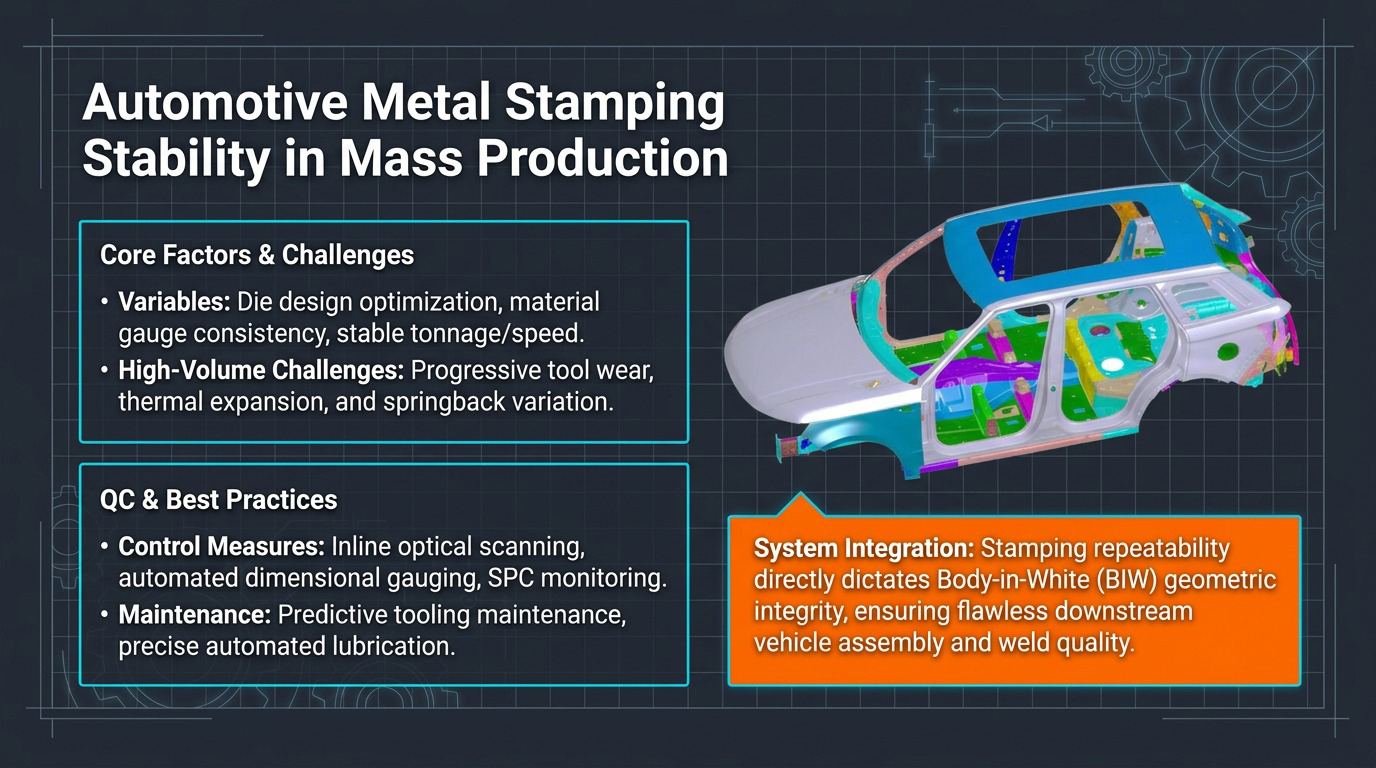
Tip 22 – Automotive metal stamping Monitoring of tool life
Keep track of tool life using stroke counts between regrindings and tool wear trends. Usual interval between regrindings of high-volume AHSS stamping dies is 50,000 to 200,000 strokes. Use collected information to schedule preventive downtimes in advance rather than waiting for emergencies.
Tip 23 – Automotive metal stamping Planned Maintenance Program
Compile a list of regular maintenance activities that include: cleaning scrap holes and scrap chutes, checking nitrogen springs for pressure drops, inspecting guides pins and bushes, checking torque values of all inserts. Properly maintained die is able to consistently outproduce optimised die in its degradation state.
Tip 24 – Checking nitrogen springs
After prolonged use of nitrogen springs pressure tends to decrease due to seal wear. Check pre-charge pressure each month using specially designed gage. Replace all springs with more than 10% lost pressure. One damaged nitrogen spring causes asymmetric forming or sudden deviations in part contour.
Tip 25 – Statistical process control (SPC)
Use statistical process control to monitor trends in critical dimensions during the tryout process. Mark measurement results after each 50 to 100 strokes. Pay attention to trends such as increasing of springback (because of die wear) or any sudden change (because of loose inserts or difference in material grade).
Tip 26 – CAE simulation support in production
Save all simulations done during die development. Use CAE simulation in production to troubleshoot: compare real formed part with simulation. It’s possible to perform various “what-if” studies such as using blanks with new shapes, different lubrication coefficients and press speeds using modern CAE technology.
Tip 27 – Automotive metal stamping management system
Document all valuable tryout experience, adjustments and process improvements into the database. In many die shops experience gained during development is stored only in heads of engineers. Lessons learned during development of different products accumulate in structured knowledge management system.
Chapter 8: F.A.Q. (Frequently Asked Questions)
8.1 What is automotive sheet metal stamping?
Automotive sheet metal stamping is manufacturing process that involves forming of flat metal sheets by stamping dies and presses into vehicle components such as body panels, brackets, structural rails and battery housings.
8.2 What kind of materials are used for automotive stamping?
Typical materials used in automotive stamping are mild steel, high strength steel (HSS), advanced high strength steel (AHSS), stainless steel and aluminum alloys (5xxx and 6xxx grades).
8.3 Why is CAE simulation important in stamping process?
CAE simulation predicts potential problems with cracking, wrinkling, springback and material flow which allows to save up to 30-50% of time and money required for tryout.
8.4 Where do wrinkles appear during deep drawing of Automotive metal stamping?
Usually wrinkles are associated with low blank holder force, poor draw bead design, excessive flow of material or imbalanced forming geometry.
8.5 How do I avoid cracking at Automotive metal stamping?
It can be prevented by using bigger radius in corners, preforming, annealing of materials, appropriate blank shape and draw beads adjustments.
8.6 What is the recommended ratio for thinning?
In general it shouldn’t be higher than 25%. Up to 40% in case of deep drawing of stainless steel parts with further annealing is acceptable.
8.7 Why use adjustable inserts?
Use of adjustable inserts allows fast tuning of dimensions in tryout stage and production which saves on tooling costs and prevents replacement of entire die.
8.8 What is fine blanking process?
Fine blanking is precision stamping process which produces nearly no clearance (less than 1%) and thus provides perfect shearing with excellent dimensional accuracy without secondary operations.
8.9 How to increase die life?
This includes use of premium tool steel, application of PVD or TiD coating, planned maintenance, scheduled regrinding and effective lubrication.
8.10 How to reduce tryout time?
Using combination of CAE simulation, optimal strip layouts, adjustable inserts and detailed tryout record reduces die development time by 30-50%.
Chapter 9: Conclusion of Automotive metal stamping
Automotive metal stamping technology is highly-specialized field combining many aspects of materials science, tooling design, CAE simulation and many years of practical experience in manufacturing. Development of electric cars and advanced materials moves die technology towards precision and durability.
Continuous loop of design → tryout → analysis → optimization → production helps to increase proportion of accepted dies, accelerate die development process and obtain efficient and profitable mass production. All of thirty presented tips were successfully tested on real-world dies and prove their effectiveness. Just use them consistently, document and constantly improve your processes.

