How Hydraulic Proportional Relief Valves Improve Control solution
Hydraulic Pilot-Operated Relief Valve for Heavy Machinery
Industrial Hydraulic Pilot-Operated Relief Valve Manual
Hydraulic Relief Valve for Excavator Pressure Control
Proportional Relief Valve for Hydraulic System Controls
Pilot-Operated Relief Valve for Industrial Hydraulic Use
How Hydraulic Proportional Relief Valves Improve Control solution
Hydraulic Pilot-Operated Relief Valve for Heavy Machinery
Industrial Hydraulic Pilot-Operated Relief Valve Manual
Hydraulic Relief Valve for Excavator Pressure Control
Proportional Relief Valve for Hydraulic System Controls
Pilot-Operated Relief Valve for Industrial Hydraulic Use

WL46302 Hydraulic Pilot-Operated Relief Valve Solutions

The WL46302 Hydraulic Pilot-Operated Relief Valve is intended for hydraulic systems where controlled and stable pressure regulation is needed. The design separates the pressure regulating function from the main flow control stage due to the pilot-operated valve architecture, which helps to provide reliable pressure regulation even under harsh operating conditions.

The concept of a hydraulic pilot-operated relief valve is that the valve can adjust its relief pressure based on the external command signal instead of providing a fixed mechanical setting. This makes the hydraulic pilot-operated relief valve an ideal component for use in a hydraulic system where the relief pressure varies based on the machine loading conditions and operating mode.

The hydraulic pilot-operated relief valve can be used in construction machinery, agricultural machinery, industrial hydraulic systems, mobile machinery, automation machinery, and other machinery requiring control of hydraulic pressure. The hydraulic pilot-operated relief valve for OEM projects should be chosen based on the working pressure, flow rate, control signal, response requirements, installation dimensions, hydraulic fluid, temperature, duty cycle, and environmental conditions.

Hydraulic Pilot-Operated Relief Valve Product Overview

The hydraulic pilot-operated relief valve is intended for use in hydraulic applications with the controlled pressure regulation and electronic integration with machine-control systems. The hydraulic pilot-operated relief valve design of the valve uses the pilot stage to control the main relief stage. Proportional control of the valve allows the user to adjust the pressure setting with the command signal.

The hydraulic pilot-operated relief valve is suitable for use in mobile machinery, construction machinery, industrial hydraulic systems, automation machinery, and customized OEM hydraulic circuits. In selecting products, consider the entire hydraulic operating environment and not just the valve pressure. Key parameters include maximum working pressure, flow requirement, control input, response characteristics, leakage, hydraulic fluid, operating temperature, installation dimensions, port configuration, and required reliability. The final product specification shall be verified with the manufacturer’s approved datasheet and drawing.

How Does the Hydraulic Pilot Operated Relief Valve WL46302 Work?

A hydraulic pilot-operated relief valve consists of the main relief stage and the pilot control stage.

Step 1—Valve receives hydraulic pressure

Hydraulic fluid enters the valve from the pressure part of the hydraulic circuit. Applying the system pressure to the valve mechanism.

Step 2 – The pilot phase controls pressure.

The pilot stage controls the pressure ratio inside the valve. The pilot stage controls the main valve instead of controlling the pressure functions directly in the main valve element.

Step 3- Electrical control to set point proportionally

The proportional control signal modifies the pilot control stage. By increasing or decreasing the signal, the relief starting pressure is changed depending on the particular valve design and control electronics.

Step 4: The main valve opens when the controlled pressure is reached.

As the hydraulic pressure rises and reaches the relief setting, the pilot stage gradually opens the main valve.

Step 5 – Release excess hydraulic pressure

The valve directs excess hydraulic flow to the return or tank circuit, keeping the hydraulic system in the pressure setting range.

Step 6 — Constant Pressure Management

The proportional relief setting of the valve is flexible to machine load changes. This provides more flexible pressure control compared to a fixed relief valve.

Important: Actual flow paths, control signal characteristics, pressure range, response time, and valve design shall be verified against the approved engineering drawing and the technical datasheet.

Key Features of a Hydraulic Pilot-Operated Relief Valve

A hydraulic pilot-operated relief valve combines pilot-stage pressure control with proportional adjustment. Typical key features are variable pressure regulation, stable hydraulic performance, controlled response, and suitability for electronically controlled hydraulic systems. The hydraulic pilot-operated relief valve design enables the main valve to control the hydraulic flow, whereas the pilot stage controls the pressure behavior. The relief setting can be adjusted to the machine requirements with the proportional control of the valve. This design can improve pressure regulation under variable hydraulic loads. Important features of the particular model include pressure range, rated flow, control signal, hysteresis, response time, leakage, temperature range, hydraulic fluid compatibility, installation dimensions, and service life.


Compact Hydraulic Pilot-Operated Relief Valve Video

Compact Hydraulic Pilot-Operated Relief Valve Detailed Display

Compact Hydraulic Pilot-Operated Relief Valve Datasheet

Brand Weilong Technology Model Number WL46302
Rated Voltage (V) DC 24V, 0.8A to 2.5A Rated Power (W) 15W to 50W
Work Mode Hydraulic Valve Working Pressure (N) 80–315 MPa
Airflow Rate 1 L/minute Reset Time(s) 1 S On, 1S Off
Service Life 200 Thousand Times Certification CE, ROHS, ISO9001,
Material Superior Magnet Iron Lead Wire Length (mm) 200 MM
Install Style Screw Tolerance of Dimension ± 0.1 MM
Water-proof None Insulation Class B
Hi-Pot Test AC 600V 50/60Hz 2s Non-excitation Holding Force 0
Working Temperature -10°C-100°C Duty Cycle 1-100%
Thread Depth (mm) / Payment Term TT, or LC at Sight
Sample Order Yes. Warranty 1 Year
MOQ 1000 pcs Supply Ability 5000 pcs per week
Delivery Time 30 Days Port of Loading Shenzhen

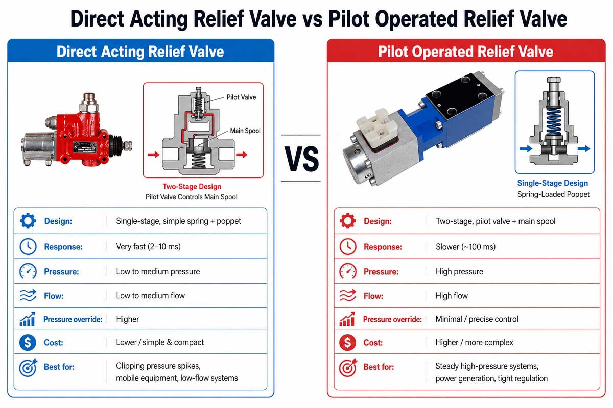
Direct Acting Valve Versus Pilot-Operated Relief Valves

Direct Acting vs Pilot Operated Relief Valves compariion

1. Comparison Table List

Comparison Direct-Acting Relief Valve Pilot-Operated Relief Valve
Operating principle The main valve responds directly to system pressure. The pilot stage controls the main valve.
Construction Generally simpler More complex
Response Can provide direct pressure response Controlled through the pilot stage
Flow capability Often suitable for smaller or moderate flow applications Well suited to higher-flow hydraulic systems
Pressure control Typically simple Can provide more sophisticated control
Proportional integration Possible depending on design Particularly suitable for proportional control architectures
Contamination sensitivity Generally lower complexity Pilot passages may require cleaner fluid.
Installation Usually simpler Requires more system considerations
Cost Often lower Generally higher
Application Basic pressure protection Advanced pressure management and higher-flow systems
Electronic control Limited depending on design Well suited to electro-hydraulic systems
Heavy machinery Suitable for simpler circuits Suitable for advanced variable-load systems

2 Direct Acting Relief Valves

The direct-acting relief valve uses system pressure directly on the spring-loaded or similar control element. The valve is opened to protect the hydraulic circuit when the pressure reaches the set value.

The main advantages of the valve are simplicity, straightforward operation, and relative easiness of the maintenance.

3 Pilot-Operated Safety Valves

The pilot-operated relief valve uses a smaller pilot stage to control the main valve. The pilot stage controls the pressure conditions that determine when and how the main valve opens.

Such design can be useful in the case of applications that require the higher flow capacity, stable pressure control, or proportional electronic control.

4. Which Valve Should Buyers Choose?

Choose the direct-acting valve if simplicity is important and the simple pressure protection is required.

If the machine needs variable pressure control, better hydraulic flow management, electronic integration, or sophisticated electro-hydraulic control, then choose the pilot-operated proportional relief valve.

In the WL46302 project, the final choice should be made based on the entire hydraulic circuit and not just the valve name.


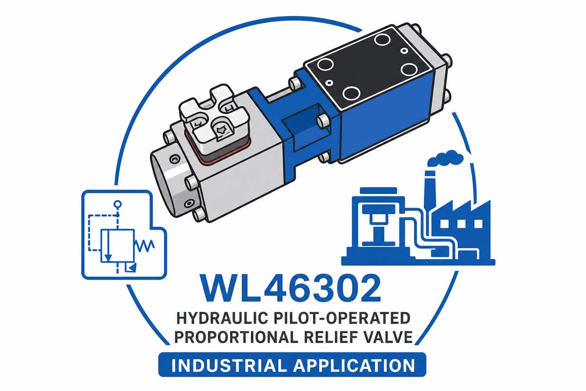
Compact Hydraulic Pilot-Operated Relief Industrial Application

Hydraulic Pilot-Operated Proportional Relief Valve Industrial Application

The hydraulic pilot-operated relief valve is widely used in hydraulic systems where pressure regulation in accordance with the machine operating conditions is required. One of the major applications of this valve is the construction machinery, including excavators, loaders, lifting equipment, and other mobile machines. Such systems usually are characterized by the variable loading conditions and require flexible pressure control.

In the proportional pressure control of the agricultural machinery, it is possible to support multiple operating modes and hydraulic functions. The electrically adjustable hydraulic pressure can be used in tractors, harvesters, sprayers, and special machinery.

The hydraulic pilot-operated relief valve can be used in hydraulic power units, production machinery, material handling equipment, forming machines, and automation systems in industrial hydraulic systems. These components help to match hydraulic pressure to machine commands.

Other applications include mobile hydraulic systems, lifting systems, machine tools, automation equipment, hydraulic test systems, and special-purpose OEM machinery.

The biggest advantage of the application is the flexibility. Instead of designing the hydraulic system for one relief setting, the control system can modify the pressure in accordance with the operating conditions. This can support multiple machine operating modes, improve energy efficiency, and increase coordination between the electronic controls and hydraulic functions.

Before making the final selection, engineers should evaluate the pressure, flow, control signal, response, temperature, fluid compatibility, installation space, and safety requirements for the particular application.

Why is the hydraulic pilot-operated relief valve gaining popularity in heavy machinery?

The hydraulic pilot-operated relief valve is more and more frequently used in heavy equipment. Modern excavators, loaders, agricultural machines, lifting equipment, and specialized mobile machinery require hydraulic systems capable of smartly responding to the changing loads and operating modes.

The standard fixed relief valves provide basic pressure protection but not the same variable pressure control. A proportional pilot-operated relief valve can integrate the hydraulic pressure-management system and electronic machine controls.

There are several significant benefits to this:

Pressure control at a variable pressure

Better capability to adjust to fluctuating loads

Electronics for machine integration

Multiple work pressure modes

Flexible hydraulic system

Potential benefits in energy management

Better combination of hydraulic and electronic systems

Integrated compact design for the newest hydraulic architectures

The design flexibility is another significant benefit for the manufacturers of heavy equipment. With the help of software, electronics engineers can control hydraulic pressure according to operating modes instead of using mechanical adjustments.

However, the popularity of the doHydraulic Pilot-Operated Relief Valve does not mean that a proportional relief valve is the best solution for all machines. The engineers still need to check pressure, flow, response, contamination level, environmental conditions, control signal, safety requirements, and system architecture.

The most useful application is the one where variable hydraulic pressure control and electronic integration can be achieved.


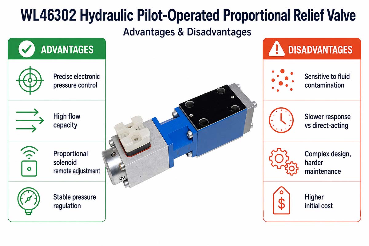
Compact Hydraulic Pilot-Operated Relief Valve Advantage and Disadvantage

Proportional Relief Valve Advantages & Disadvantages

Hydraulic Pilot-Operated Relief Valve Advantages

A hydraulic pilot-operated proportional relief valve is very beneficial to modern hydraulic systems. It allows for proportional control because machine commands and conditions can alter the pressure setting. In comparison with the traditional fixed relief valve, the valve under review is more flexible.

The architecture of the pilot-operated valve allows for effective pressure management while letting the main valve control the hydraulic flow. It is very useful in case of machines working with varying loads in multiple ways.

Another significant advantage is that you can control it electronically. The valve can be included in the electro-hydraulic control system where the hydraulic pressure depends on machine logic.

Proportional pressure control could also make simpler the use of various OEM equipment operating modes.

Hydraulic Pilot-Operated Relief Valve Disadvantages.

One of the main disadvantages is associated with the increased complexity of the system in comparison with the simple direct-acting relief valve. The valve could require the additional control electronics, wiring, calibration, and commissioning.

It is also more sensitive to contamination, as the small pilot passages and control elements require the clean hydraulic fluid.

The correct sizing is crucial because the unstable operation or absence of pressure protection could be caused by improper pressure, flow, control signal, or installation parameters.

The last but not least is the higher initial cost of the valve in comparison with the basic fixed relief valve. Thus, the proportional pilot-operated design is most valuable in the case of justification of its complexity.

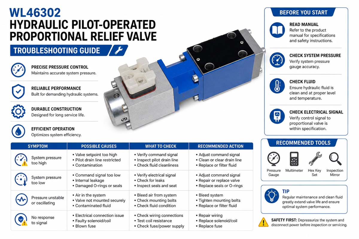
Troubleshooting of a Hydraulic Pilot-Operated Proportional Relief Valve

Hydraulic Pilot-Operated Proportional Relief Valve Troubleshooting Guide

Troubleshooting a Hydraulic Pilot-Operated Proportional Relief Valve The first step in troubleshooting a hydraulic pilot-operated proportional relief valve is to determine whether the problem is related to mechanics, hydraulics, electricity, or system integration.

Problem 1. Too much pressure

The command signal, proportional signal, controller output, pilot stage, pressure setting, and hydraulic circuit should be checked. Ensure that the valve is properly installed and that the pressure measuring device is appropriate.

Problem 2. Low pressure

Check whether the control signal is appropriately reaching the valve. Check hydraulic supply, pilot circuit, valve setting, contamination, and internal leakage.

Problem #3. Pressure oscillations

The causes of the pressure instability can be contamination, presence of air in the hydraulic circuit, improper flow conditions, unstable electronic signals, incorrect sizing, and interaction with other hydraulic components.

Problem 4. No valve response

Check the electrical supply, proportional driver, connector, wiring, command signal, and grounding. Then verify the hydraulic circuit and pilot stage.

Problem 5. Heat is too high.

Check for any continuous relief flow, excessive pressure drop, improperly sized valve, restricted return flow, and inappropriate operating conditions.

Problem 6. Leak

Check for the external connections, seals, mounting surfaces, and internal leakage conditions. Verify the leakage within the specified acceptance limit.

Problem 7. Changes in performance depending on the temperature

Check hydraulic oil viscosity, operating temperature, seals, and valve specifications.

During the systematic troubleshooting process, pressure, flow, temperature, control signal, and operating conditions should be recorded before changing any components.

8 FAQS of Hydraulic Pilot-Operated Relief Valve

1. Pilot operated proportional relief valve: What is it? How does it work?

It is the pressure control valve that sets the maximum pressure of the system proportional to an electrical signal. It consists of the main valve and pilot valve. The pressure in the main valve control chamber is controlled by the pilot valve, usually operated by a proportional solenoid. Varying the electrical current, the pressure setting of the pilot valve is adjusted. It provides smooth, stepless control over a wide range. In a typical configuration, increasing the solenoid current will increase the set pressure.

2. How does a proportional pilot operated relief valve differ from a standard pilot operated relief valve?

A typical relief valve for pilots has a set pressure setting. It is usually set by hand with a spring. Conversely, a proportional valve gets an electrical input signal and continuously adjusts its pressure setting proportionally. It provides the dynamic remote control of system pressure, which is crucial to complex, automated processes.

3. What are the main performance characteristics that I should be aware of?

Look for the key specifications, such as

Hysteresis – difference in pressure at which a valve opens and closes for a given input signal. It is usually expressed in percent, with lower values (<4-8%) indicating better accuracy.

Linearity: how much the output pressure follows the input signal in a straight line.

Reseat Pressure: the pressure at which the valve re-closes, usually a high percentage (e.g., >85%) of the cracking pressure.

Dither: Usually the high-frequency AC signal (e.g., 100-250 Hz) added to the command signal to reduce hysteresis and improve response.


4. How contamination affects this valve?

The main cause of failure is contamination. The pilot stage is very sensitive to dirt with small orifices and tight clearances. If the control orifice is clogged, it may behave erratically or fail altogether. For example, the partially clogged orifice in the pilot-operated relief valve results in the system relief at a lower pressure than necessary. In one troubleshooting case, the clogged orifice was the cause of the system not reaching the proper pressure.

5. What is the "fail-safe" position of these valves?

Many proportional relief valves are designed to fail-safe. For example, an “inversely proportional” valve will automatically return to its highest pressure setting in the event of an electrical failure (such as loss of power). This is done for safety purposes to ensure that the hydraulic system has the maximum available pressure for critical actuators.

6. Is this valve used for energy saving applications?

Yes. One of the common applications is to use these valves to “unload” a pump circuit at low pressure when full flow is not needed. The valve will substantially decrease energy consumption, minimize heat generation, and improve the overall system efficiency by proportionally reducing the system pressure during standby or light-load conditions. Some models are specially designed for this application and have high flow ratings to be able to handle the full pump output.

7. What is the function of an external drain port?

The external drain ports are used to provide an entirely separate return path for the pilot oil to the tank. This is very important, as it prevents the back pressure in the tank line from directly affecting the set pressure of the valve, thus providing more precise control. Some designs have an external drain port (usually marked “Y”) so that the valve can be used as a sequence valve as well.

8. What is the effect of back pressure at the tank port on performance?

Back pressure at the tank port (port 2) adds directly to the valve setting on a 1:1 basis. This means that any pressure in the return line will add to the system pressure required to open the valve, potentially resulting in inaccurate pressure control.


How to Choose a Hydraulic Pilot-Operated Relief Valve?

The WL46302 selection is not based solely on the hydraulic system pressure. Before issuing the purchase order, the whole operating environment should be reviewed and the valve requirements defined by the engineers.

1. Define the pressure range

Define the normal operating pressure, the relief pressure required, the minimum and maximum pressure settings, and the pressure fluctuations. The pressure range of the valve should cover the actual application, but the valve should not operate continuously at an unsuitable limit.

2. Define the required flow rate

Calculate the maximum flow that can be passed through the relief valve. Incorrect sizing of the valve can result in excessive pressure drop, unstable operation, heat generation, or inadequate pressure protection.

3. Define the proportional control signal.

Define if there is a need for a certain percentage of electrical input in the application. Control voltage/current, command range, connector, polarity, and driver characteristics should be defined prior to the production.

4. Assess response requirements

Some machines require rapid pressure changes while others require smooth and stable regulation. Define response time, pressure ramping, hysteresis, repeatability, and dynamics if required.

5. Check hydraulic fluid compatibility

Define the hydraulic oil or other fluid used in the hydraulic system. Make sure that seals, internal materials, coatings, and valve parts are compatible with the fluid selected.

6. Check installation requirements

Check the port size, port type, mounting style, envelope dimensions, orientation, electrical connector, and installation space. Mechanical interfaces should be verified on the approved 2D drawing or 3D model.

7. Consider environmental conditions.

Define operating temperature, ambient temperature, vibration, shock, humidity, contamination, corrosion exposure, and protection requirements.

8. Define expectations for reliability

Define the service life, duty cycle, test requirements, leakage limits, pressure stability, and inspection criteria for OEM applications.

9. Check safety requirements

A relief valve is an important safety component of the hydraulic system. The entire circuit should be reviewed for fail-safe behavior, emergency conditions, maximum pressure, and machine safety requirements.

10. Approve the samples prior to mass production.

For a WL46302 customized project, the prototype tests should confirm the pressure control, flow performance, response, leakage, temperature behavior, electrical compatibility, and mechanical installation prior to the mass production.

How to Avoid Common Design Pitfalls during the Design of a Hydraulic Pilot-Operated Relief Valve

Error 1: Only pressure requirement is provided.

Pressure alone won’t work. Include pressure, flow, control signal, temperature, hydraulic fluid, and application conditions.

Mistake 2: Failure to define the control signal

The proportional valve should fit its controller. The voltage/current command requirements and control characteristics should be clearly defined.

Mistake 3: Using an Unapproved Drawing

Minor changes in port location, mounting dimensions, connector position, or envelope size can lead to major installation problems.

Mistake 4: Failing to define hydraulic fluid

Seal material compatibility should be confirmed prior to the production.

Mistake 5: Failure to define dynamic requirements

If rapid pressure change is required, dynamic requirements should be defined in the design phase.

Mistake #6: Testing at room temperature only

Temperature influences hydraulic oil viscosity and valve performance. The test should reflect the real operating conditions.

Mistake 7: Simultaneously changing multiple parameters

When possible, change one major variable during prototype evaluation. Makes troubleshooting much easier.

Mistake 8: Failing to define acceptance criteria

Prior to ordering samples, agree on pressure accuracy, flow, leakage, response, electrical behavior, dimensions, endurance, and inspection methods.

Mistake #9: Assuming that the sample is production-ready by default

The prototype has to be tested against the final application. Mass production should not be started until the engineering approval is complete.

 

Get A Free Quote Now

Contact Form

Related Products

Related News

Scroll to Top

Get A Free Quote Now !

Contact Form
If you have any questions, please do not hesitate to contact us.
Weilong Solenoid Company Culture
