Chapter 1: Introduction
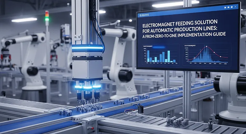
In the automatic production line of hardware accessories, the feeding link is a key node affecting overall efficiency. Many enterprises still adopt manual feeding, which not only has low efficiency (each worker can only complete 800 feedings per hour) but also is prone to material positioning deviations due to human errors, affecting subsequent processing accuracy. Combining the actual transformation case of a hardware factory, this article comprehensively disassembles the entire process of design, implementation and optimization of the electromagnet feeding solution, and supplements the core advantages, disadvantages and common problem solutions of the solution, helping you quickly implement automatic feeding transformation and achieve dual improvement in efficiency and accuracy.
Chapter 2: Disassembly of Core Scene Requirements
Material Characteristics: The materials to be conveyed are hardware accessories with a weight range of 0.5-2kg and made of ferroalloy. The core requirement is to achieve continuous high-frequency feeding with a target frequency of ≥1500 times per hour;
Accuracy Requirement: The feeding positioning deviation must be strictly controlled within ≤0.5mm to avoid affecting subsequent key processing procedures such as stamping;
Environmental Requirement: There are harsh working conditions such as oil stains and dust on the production line, and the electromagnet must be guaranteed to operate stably for a long time without failure shutdown.
Chapter 3: Design of Electromagnet Feeding Solution
Push and Pull Solenoid Selection: A high-frequency response push-pull DC electromagnet is specially selected, model MGP-20, rated voltage 24V DC, response time ≤0.05s, which can perfectly match the high-frequency feeding demand; the coil adopts oil-resistant and high-temperature-resistant enameled wire with a protection level of IP65, which can effectively resist oil stains and dust erosion on the production line and adapt to harsh working conditions;
Transmission Structure Design: Equipped with a high-precision ball screw transmission mechanism, the feeding claw is directly driven by the telescopic action of the electromagnet. With the low friction and high precision characteristics of the ball screw, the feeding positioning accuracy is further guaranteed;

Chapter 4: Control System
Connected to Siemens S7-200 PLC to achieve precise synchronization between the on-off state of the electromagnet and the feeding rhythm; it supports flexible adjustment of feeding parameters according to different material specifications, and has strong scene adaptability.
Chapter 5: Key Steps of Implementation and Commissioning
Installation and Calibration: Firmly fix the electromagnet on the feeding mechanism bracket, accurately adjust the telescopic stroke of the electromagnet (set to 10mm), ensure the accurate contact position between the feeding claw and the material, and initially control the positioning deviation within 0.3mm;
No-Load Commissioning: Independently test the high-frequency response performance of the electromagnet, continuously run it under no-load condition for 1 hour, record the response time stability and equipment heating in real time, ensure the stable operating temperature ≤60℃, and avoid affecting the service life due to overheating;
Load Commissioning: Gradually increase the feeding frequency from 1000 times/hour to 1800 times/hour, observe the change of material positioning accuracy and the operation stability of the electromagnet throughout the process, solve problems such as material jamming and feeding delay that may occur during the feeding process by optimizing PLC parameters, and finally lock the optimal operating parameters.
Chapter 6: Verification of Implementation Effect
After the transformation and implementation, the feeding efficiency of the production line has achieved a significant leap: from 800 times/hour of manual feeding to 1500 times/hour, with an efficiency increase of 40%; the feeding positioning accuracy has been further optimized, and the deviation has been stably controlled within 0.3mm, directly driving the processing scrap rate down from the original 3.2% to 0.8%; the labor cost has been significantly reduced by 50%, originally 2 workers were specially responsible for feeding, and only 1 worker is needed to monitor the equipment operation after the transformation.
Chapter 7: Analysis of Core Advantages and Disadvantages of the Solution
(I) Core Advantages
High Frequency, High Efficiency and Strong Adaptability: The Push and Pull Solenoid selected high-frequency response. Push and Pull Solenoid can meet the feeding demand of ≥1500 times/hour, far exceeding manual efficiency, and can adapt to different specifications of ferroalloy hardware accessories, and the material type can be switched by adjusting parameters;
High Positioning Accuracy and Stability: Equipped with ball screw transmission and precise PLC control, the positioning deviation is stably within 0.3mm, effectively reducing the processing scrap rate; the electromagnet has a protection level of IP65, which is oil-resistant and dust-resistant, and has a low failure rate under harsh working conditions;
Controllable Transformation Cost: Compared with complex feeding equipment such as manipulators, the Push and Pull Solenoid feeding solution has lower hardware cost, and can be compatible with the original PLC system of the production line, reducing transformation investment and commissioning cycle;
Simple Operation and Maintenance: The equipment structure is simple, workers can complete daily monitoring and basic maintenance after simple training, and no professional operation and maintenance team is needed in the later stage, reducing operation and maintenance costs.
Chapter 8: Core Disadvantages
Limitation of Material Properties: Only applicable to magnetic materials such as ferroalloy, non-magnetic hardware accessories (such as aluminum alloy, copper alloy) cannot be directly adapted, and additional magnetic adsorption accessories need to be installed, increasing the adaptation cost;
Limited Load Capacity: Limited by the suction force of the electromagnet, it can only adapt to materials of 0.5-2kg. For heavy hardware accessories exceeding 2kg, a larger power electromagnet needs to be selected, which may lead to increased equipment volume and energy consumption;
Dependence on Stable Power Supply: The operation of the electromagnet depends on stable 24V DC power supply. If there is voltage fluctuation, it is easy to cause response delay or insufficient suction, and a voltage stabilizer needs to be equipped.
Chapter 9: Common Problems and Solutions
Problem 1: Severe heating of the electromagnet during high-frequency operation, exceeding 60℃ Solution: Check whether the heat dissipation channel is unobstructed and clean the oil stains and dust on the surface of the electromagnet; appropriately reduce the continuous operation frequency and set an intermittent heat dissipation time of 5-10 minutes; if the problem still not improved, replace with an electromagnet model with higher power.
Problem 2: Material jamming during feeding Solution: First, check the fit between the feeding claw and the material, and re-calibrate the telescopic stroke of the electromagnet; second, check the PLC feeding parameters and adjust the feeding rhythm and the on-off time difference of the electromagnet; finally, check whether there is jamming in the transmission mechanism and add grease to reduce friction.
Problem 3: Positioning deviation exceeds 0.5mm, affecting processing accuracy Solution: Re-calibrate the ball screw transmission mechanism and check for looseness; adjust the fixed position of the electromagnet to ensure the precise movement trajectory of the feeding claw; optimize the PLC control parameters to improve the synchronization of the electromagnet’s on-off response.
Problem 4: Push and Pull Solenoid failure and shutdown under harsh environments Solution: Regularly clean and maintain the electromagnet to remove oil stains and dust on the surface; check the coil sealing condition, and timely replace the oil-resistant and high-temperature-resistant coil if the enameled wire is damaged; install a protective cover to further isolate oil stains and dust.
Problem 5: Insufficient suction due to voltage fluctuation, resulting in unstable material adsorption Solution: Install a voltage stabilizer in the power supply circuit to ensure stable 24V DC voltage; check whether the line connection is firm and replace aging lines; appropriately increase the power supply voltage (not exceeding 10% of the rated voltage) according to the material weight.
Chapter 10: Experience Summary
Selection requires “double matching”: it must not only match the high-frequency response demand of the scene to ensure the response time ≤0.05s, but also match the harsh working condition environment. Priority should be given to models with IP65 or above protection level and oil-resistant and high-temperature-resistant coils to avoid failures due to improper selection;
Push and Pull Solenoid Solution design requires “strong compatibility”: during the design of the feeding solution, it is necessary to connect with the original PLC system of the production line in advance, confirm the parameter compatibility range, and reduce the later commissioning cycle and transformation difficulty; high-precision components should be preferred for the transmission structure to ensure positioning accuracy from the source;
Commissioning process requires “step-by-step progress”: strictly follow the commissioning principle of “from no-load to load, from low frequency to high frequency”, gradually optimize parameters, and record equipment operation data in real time to avoid equipment damage or solution implementation failure due to eagerness for success;
Later maintenance requires “normalization”: regularly clean and inspect the electromagnet, transmission mechanism and control system, establish a maintenance account, predict potential failures in advance, extend the service life of the equipment, and ensure the continuous and stable operation of the production line.