Chapter 1: Introduction: Key Actuators in Stamping Automation
In the metal stamping industry, stamping presses are the core equipment for achieving efficient, high-volume metal forming. With the continuous advancement of stamping automation technology, higher demands are being placed on the response speed, operational reliability, and system coordination of auxiliary actuators. Push-type solenoid, due to their advantages such as linear output, rapid action, and simple structure, are widely used in key functions of metal stamping presses, such as feed control, positioning, material blocking, and safety interlocking.
This article provides a comprehensive analysis of the practical application of push-type solenoid valves in metal stamping presses. From engineering requirements to implementation verification, it delves into the advantages and disadvantages of their application and strategies for solving common problems, providing a practical reference for the design and maintenance of stamping automation.
Chapter 2: Scenario Requirements: Core Requirements of Press Machine Actuators
Stamping presses, when operating at high speeds, necessitate that several auxiliary actions are meticulously synchronized with the primary stroke. The following are typical requirements:
2.1 High-speed response and precise timing are essential. The stamping cycle is extremely rapid, often reaching hundreds of strokes per minute. Consequently, operations such as pushing, blocking, positioning, or releasing must be executed within a few tens of milliseconds; failure to do so can result in feed misalignment, material accumulation, or die damage.
2.2 Significant instantaneous thrust is also required. The actuating mechanism must counteract material friction, spring force, and inertial resistance, thereby necessitating that the actuator deliver a stable and adequate instantaneous thrust, typically measured in tens to hundreds of Newtons.
2.3 High-Frequency Operation and Longevity
Stamping equipment is designed for year-round continuous operation. Consequently, the auxiliary actuators must demonstrate the capacity to endure hundreds of thousands, if not millions, of cycles over the machine’s operational lifespan, thereby ensuring enduring stability and mechanical integrity.
2.4 Compact Design and Maintenance Accessibility
Given the constraints of internal space within a stamping press, the actuator must be readily installable and replaceable, while also demonstrating resilience against demanding industrial conditions, including exposure to oil, dust, and vibration.
2.5 Limitations of Conventional Approaches
In the aforementioned contexts, the utilization of motors coupled with mechanical conversion mechanisms presents challenges, including sluggish response times, intricate structural designs, and elevated maintenance expenditures.
Push-type solenoid, characterized by their straightforward design and capacity for direct linear thrust output, have emerged as the optimal selection for automated auxiliary functions within stamping operations.
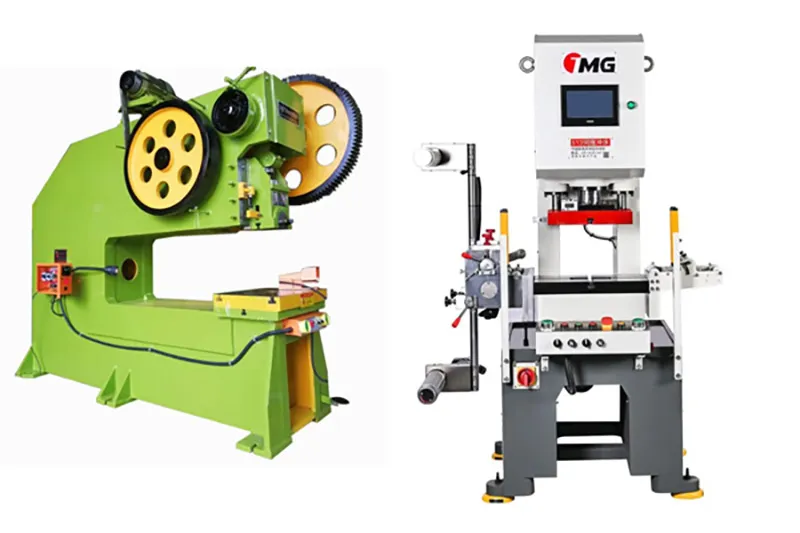
Chapter 3: Solution Design
Selection and Configuration of Push-Type Solenoid in Stamping Presses
In the solution design phase, the selection and configuration of push-type solenoid valves necessitate a close integration with both the stamping process and the equipment’s structural elements to ensure effective system implementation.
3.1 Typical Applications
Extension and retraction of the feed positioning pin: This function is critical for achieving precise material positioning.
Rapid actuation of the blocking mechanism: This feature governs the rhythm of material conveyance.
Part ejection or auxiliary pushing: This capability facilitates automatic unloading.
Safety interlock devices and anti-misoperation devices: These components are essential for safeguarding both equipment and personnel.
3.2 Push Type Solenoid Type Selection
The preferred push type solenoid is a direct current push-type, chosen for its operational stability, ease of control, and rapid response characteristics. A spring-assisted power failure reset mechanism is incorporated to guarantee that the equipment reverts to a secure state following a power interruption or system failure. Furthermore, environmental adaptability is a key consideration, necessitating the selection of a protection level appropriate for environments characterized by oil and dust.
3.3 Design of Key Parameters
The operating voltage is generally set at 24V DC, aligning with industrial control standards while simultaneously ensuring both safety and optimal performance. Thrust and stroke specifications are meticulously calculated, taking into account material thickness, friction, and the mechanism’s stroke, with suitable safety margins. The response time is critical, necessitating a rapid input, typically less than 20 milliseconds, to accommodate the demands of high-speed stamping cycles.
Duty cycle: Choose a duty cycle—continuous, intermittent, or short—that suits the operating frequency.
3.4 Structural and protective design
Reinforced housing: A metal housing or reinforced structure is essential to absorb impact vibrations.
Protective design: Dustproof and oil seal features are incorporated to cope with the stamping workshop’s conditions.
Heat dissipation considerations: Steps are necessary to keep the coil temperature in check during high-frequency operation and to manage heat effectively.
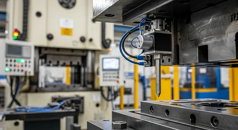
Chapter 4: Implementation and Debugging Integrating the pull-type solenoid with the Stamping System
During assembly and commissioning, the performance of push-type solenoid requires optimization through system calibration.
4.1. Travel and position calibration
Avoiding overtravel of the push rod is critical; it mustn’t interfere with the mold or the workpiece. The endpoint of the action should remain consistent.
4.2. Power supply timing debugging is essential. This involves synchronizing with a PLC or pressure control system to precisely manage the timing of power pulses. The goal is to deliver sufficient thrust and timely action, perfectly aligned with the main stroke.
4.3. Action consistency testing is necessary. This involves verifying the stability and repeatability of the push rod’s movement under continuous high-speed stamping conditions, effectively simulating the actual production cycle.
4.4. Safety interlock verification is also important. The solenoid valve must be able to reliably reset during abnormal shutdowns, power outages, or emergency stops to prevent any malfunctions.
Key points for commissioning:
Successful commissioning necessitates the precise coordination of mechanical installation, electrical parameter alignment, and control logic optimization.
Chapter 5: Application Results: Reliability and Production Efficiency Assessment
Prior to mass production, push-type solenoid valves require thorough validation to confirm their adherence to production specifications:
5.1. High-frequency durability testing
Long-term continuous operation tests, simulating actual production cycles and typically encompassing millions of cycles, are conducted to evaluate thrust decay, temperature elevation, and mechanical wear.
5.2. Environmental adaptability test
Operational stability and protective efficacy are verified through operation within a simulated environment characterized by dust, oil, and vibration.
5.3. Verification of overall machine efficiency
Comparative tests were conducted to quantitatively evaluate the improvements in feed stability, stamping yield, and overall equipment efficiency (OEE) after the introduction of push-type solenoid valves.
Actual data shows that properly selected and calibrated push-type solenoid valves can significantly reduce feed anomaly rates (up to 70% or more) and the risk of die damage, thereby improving the overall efficiency of the stamping production line by 15%–30%.
Chapter 6: Analysis of Core Strengths and Limitations
The core advantages of push-type solenoid valves in stamping machines:
- Extremely fast response speed: direct linear drive, no intermediate conversion mechanism required; the engagement time is typically 10-50 milliseconds, meeting the requirements of high-speed stamping cycles.
- Simple and reliable control: It can be controlled simply by turning the power on/off; the drive circuit is simple and has a low failure rate.
- Compact structure: Small in size, easy to arrange and install in the limited space of a stamping machine.
- Easy to maintain: The modular design allows for quick replacement in case of failure, minimizing downtime. Cost-effective: Lower initial investment and maintenance costs compared to pneumatic, hydraulic or servo systems.
- Enhanced safety: Automatic reset after power failure meets the safety design requirements of mechanical equipment.
Chapter 7: Main limitations in application
- Thrust and stroke limitations: Thrust and stroke are inversely proportional; the longer the stroke, the smaller the thrust.
- Temperature rise issue: Coils are prone to overheating during high-frequency continuous operation, which may affect performance and service life.
- Significant mechanical impact: High-speed pull-in generates enormous impact force, placing higher demands on the self-structure and connecting components.
- Energy consumption in the extended state: Maintaining the extended state requires continuous power, which leads to increased energy consumption and temperature.
- Relatively limited accuracy: Position control accuracy is usually lower than that of servo systems, and it is suitable for point-to-point control rather than precise continuous control.
- Environmental sensitivity: Although extremely cold environments can provide some protection, they can still affect service life and reliability.
Chapter 8: Common Problem Analysis and Solutions
Question 1: The solenoid valve has insufficient thrust and cannot fully drive the mechanism.
Possible causes: undersized component; low power supply voltage; short circuit in the coil; excessive mechanical resistance.
Solution: Recalculate requirements and replace with a suitable model; check the power cord to ensure stable voltage; test coil resistance and replace the faulty solenoid valve; optimize the mechanical structure to reduce friction.
Question 2: The response time is too slow to keep up with the stamping cycle.
Possible causes: coil aging; insufficient power supply; control signal delay; mechanical jamming.
Solution: Replace the solenoid valve; check the power supply capacity and upgrade if necessary; optimize the PLC program to reduce signal delay; clean and lubricate the mechanical moving parts.
Question 3: Elevated temperatures during high-frequency operation result in diminished performance.
Potential causes include: inappropriate duty cycle selection; inadequate heat dissipation; operating frequency surpassing the specified limit; and excessively high ambient temperatures.
Remedial actions involve: choosing solenoid valves with higher duty cycles; enhancing ventilation and heat dissipation; optimizing processes to decrease operating frequency; and augmenting forced cooling measures.
Question 4: Electromagnetic coil failure.
Potential causes encompass: continuous power-on duration exceeding the rated value; overvoltage; substandard coil quality; and insufficient heat dissipation.
Solutions entail: strictly regulating power-on time, and employing pulse drive when warranted; stabilizing power supply voltage; selecting dependable brand products; and ensuring effective heat dissipation.
Question 5: Push rod reset failure or incomplete reset.
Potential causes include: fatigue or breakage of the return spring; a stuck push rod; mechanical interference; and excessive residual magnetism within the iron core. Solutions: Substitute the return spring; clean and lubricate the push rod and guide elements; examine and modify the mechanical configuration; employ materials with minimal residual magnetic characteristics or implement demagnetizing techniques.
Question 6: Excessive noise
Potential causes: inadequate installation; excessive impact velocity; mechanical resonance; electromagnetic vibration.
Solutions: Secure mounting bolts; incorporate a buffer mechanism to mitigate impact; modify the installation approach or introduce damping to prevent resonance; assess power quality to eliminate electromagnetic interference.
Chapter 8: Summary of Experiences and Best Practice Recommendations
Drawing upon practical experience from numerous stamping automation projects, the following critical points have been distilled:
8.1. Considerations during the selection phase
Maintain tolerances in thrust and stroke: avoid prolonged operation under extreme parameters; a margin of 20%–30% is typically advised.
Select a solenoid valve with a duty cycle that matches the actual operating frequency and duty cycle.
Consider environmental factors: Choose the right protection level, taking into account the conditions at the stamping site, such as oil, dust, and temperature.
8.2. Installation and debugging tips
Make sure everything lines up: The push rod and load mechanism need to be perfectly aligned to minimize sideways forces.
Use cushioning: In applications with high speeds, use mechanical cushioning to lessen impact and noise.
Fine-tune control timing:
Ensure the stamping control system and the main system are perfectly in sync, preventing premature or delayed actions.
8.3. Maintenance Considerations
Routine inspection and cleaning are essential: Consistently remove any contaminants and signs of wear from the core surface.
Keep an eye on temperature: Regularly monitor the operating temperature; a significant increase often signals an impending problem.
Establish preventative replacement schedules: Create periodic replacement plans for critical components that experience frequent use.
8.4. Collaborative Design Principles
The ultimate outcome hinges on the mechanical structure’s compatibility: Only through an optimized mechanical structure can the solenoid’s performance be fully realized.
Integrated electrical control design: The electromagnetic drive circuit and control logic must be deeply integrated with the pressure control system.
Safety interlocks are crucial: design comprehensive safety interlock logic to ensure that equipment remains in a safe state under abnormal conditions.
Chapter 9: Conclusion: A reliable choice for high-load industrial environments
In high-load, high-frequency industrial equipment such as metal stamping presses, push-type solenoid valves have become a key component of automated auxiliary mechanisms due to their advantages such as fast response speed, linear output, and high reliability. Through scientific demand analysis, reasonable solution design, rigorous verification processes, and targeted problem prevention and resolution measures, push-type solenoid valves can provide stable, efficient, and economical drive solutions for metal stamping equipment.
As stamping automation advances towards higher speeds and precision, push-type solenoid valve technology is also continuously evolving. Innovations such as low-power design, intelligent condition monitoring, and extended service life will further enhance its value in the stamping field. Proper selection, reasonable application, and standardized maintenance will enable push-type solenoid valves to play a greater role in metal stamping automation, providing reliable guarantees for improved production efficiency and product quality