In the electromagnet industry, whether you are involved in technical R&D, manufacturing, or procurement, mastering professional solenoid terminology is essential in first step. As a key actuator that converts electrical energy into mechanical motion, an electromagnet’s technical parameters and structural definitions directly influence product performance, reliability, and selection.
This article explains 13 commonly used solenoid terminology terms in the electromagnet industry, helping you build a solid and practical technical foundation to select a solenoid.
Chapter 1: What is a solenoid/ an electromagnet?
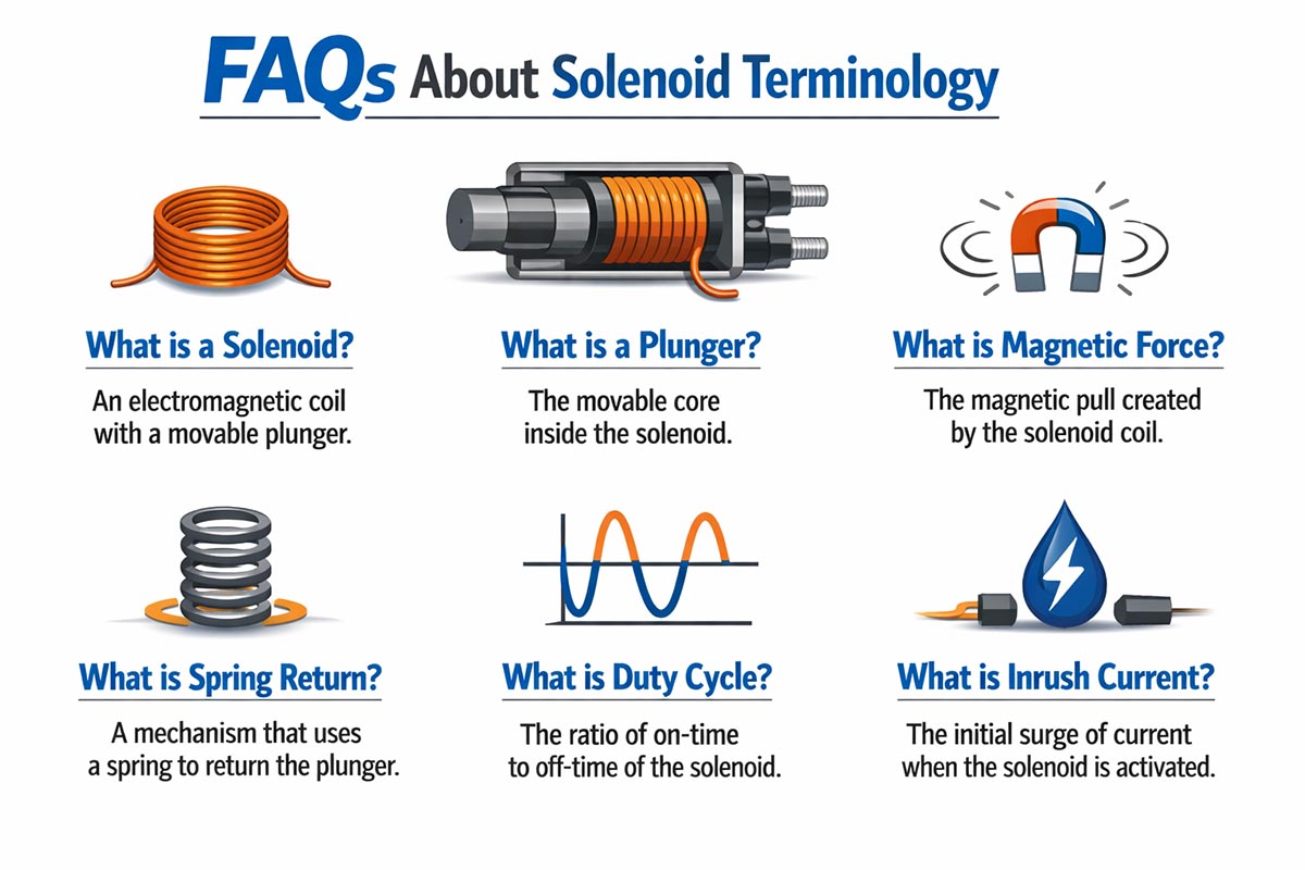
A solenoid is an electromagnet device that converts electrical energy into mechanical motion through electromagnetic force. It typically consists of a coil and an iron core. When energized by AC or DC power, the coil generates a magnetic field that drives the movable core (plunger) to produce linear motion such as pushing or pulling.
Solenoids (electromagnets) are generally classified into the following:
DC Solenoid – stable operation, widely used in automation and precision devices
AC Solenoid – faster response, commonly used in industrial control systems
Chapter 2: Rated Stroke of solenoid Terminology
Rated stroke refers to the guaranteed travel distance of the movable core, usually expressed in millimeters (mm).
It defines the effective working range from the initial position to the fully actuated position. If the required application stroke exceeds this value, the electromagnet may fail to deliver sufficient force or operate reliably.
Chapter 3: Rated Attraction Force of solenoid terminology
Rated attraction force is the force generated by the electromagnet under rated voltage across its stroke range.
Since magnetic force increases as the air gap decreases, the maximum force typically occurs at the نهاية (end) of the stroke. Therefore, datasheets usually specify the force at full stroke completion.
Chapter 4: Rated Power Consumption of solenoid terminology
Rated power consumption is the electrical power dissipated by the coil under rated voltage, expressed in watts (W).
This parameter directly affects:
Temperature rise
Energy efficiency
Coil lifespan
Excessive power can lead to overheating, insulation damage, or coil failure, especially in continuous-duty applications.
Chapter 5: Holding Force of solenoid terminology
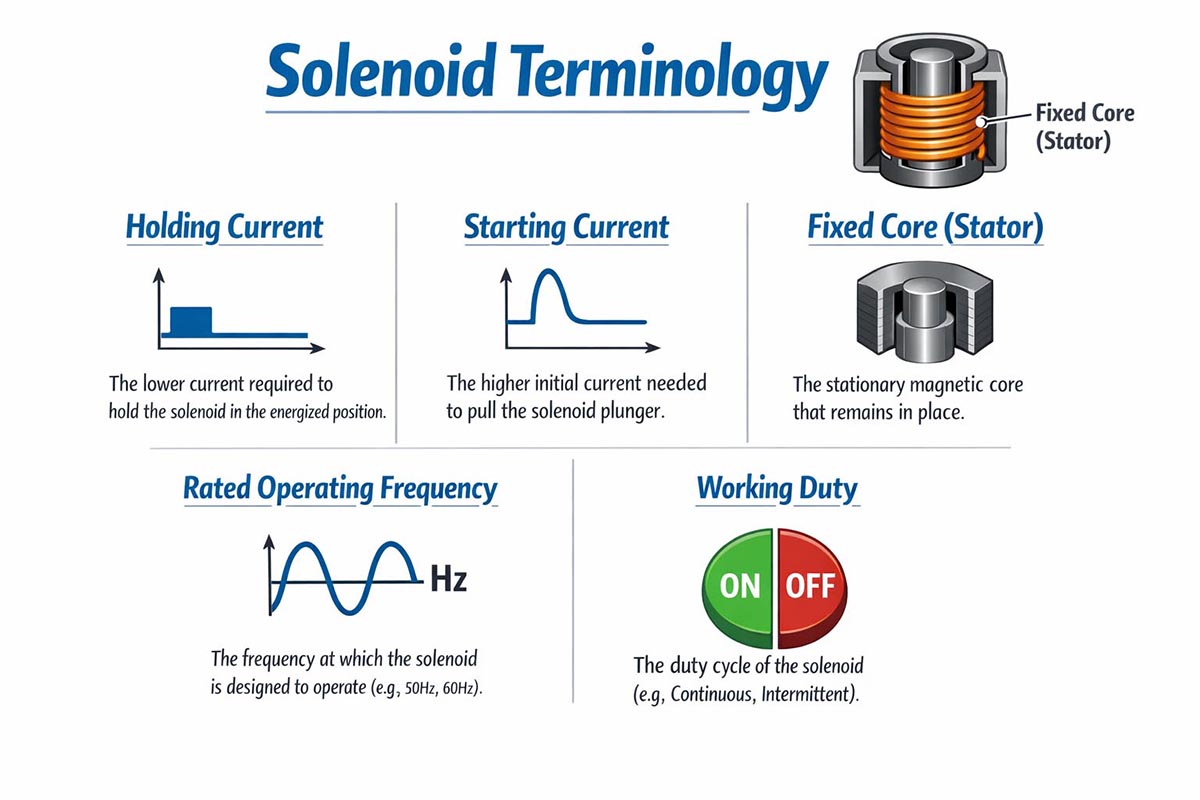
Holding force is the maximum load that the solenoid can (hold) when the movable core is fully attached.
At this position, the magnetic circuit has a minimal air gap and the lowest reluctance, resulting in maximum magnetic force, which is typically much higher than the initial attraction force.
Chapter 6: Holding Current of solenoid terminology
Holding current is the current required to maintain the electromagnet in the fully attracted position.
Because the magnetic circuit is closed, less energy is needed. Many systems use:
High current for pull-in
Reduced current for holding
This approach improves energy efficiency and reduces heat generation.
Chapter 7: Starting Current of solenoid terminology
Starting current is the current drawn when the electromagnet is first energized, with the plunger at its initial position.
Due to the large air gap and low inductance at startup, the current is typically higher than the holding current. This is important for:
Power supply sizing
Control circuit design
Chapter 8: Fixed Core (Stator) of solenoid terminology
The fixed core is the stationary part of the magnetic circuit, usually integrated with the coil and housing.
Its material (typically soft magnetic steel) and design affect the following:
Magnetic efficiency
Response speed
Energy conversion performance
Chapter 9: Movable Core (Plunger / Armature) of solenoid terminology
The movable core is the moving component driven by the magnetic field.
Its performance depends on:
Surface treatment
Alignment and guiding precision
Interaction with return springs
These factors directly influence durability and operational stability.
Chapter 10: Rated Operating Frequency of solenoid terminology
Rated operating frequency refers to the maximum number of operating cycles per unit time (e.g., cycles/hour or cycles/minute) that the electromagnet can perform while maintaining normal performance.
Exceeding this limit may cause:
Excessive heat buildup
Increased mechanical wear
Reduced service life
Chapter 11: Working Duty (Duty Cycle) of solenoid terminology
Working duty, or duty cycle, describes the ratio of energized time to total cycle time, usually expressed as a percentage.
Examples:
100% duty cycle – continuous operation
50% duty cycle – energized half the time
Intermittent duty – short bursts with cooling intervals
Selecting the correct duty cycle is critical to prevent overheating and ensure long-term reliability.
Chapter 12: Lifespan (Service Life) of solenoid terminology
“Lifespan” refers to the total number of operating cycles an solenoid can perform under specified conditions before failure or significant performance degradation.
It depends on:
Operating frequency
Load conditions
Duty cycle
Temperature rise
Mechanical wear
Typical lifespan is expressed in cycles (e.g., 500,000 to several million cycles).
IP Rating (Ingress Protection)
Chapter 13: IP Rating defines the level of protection against solid particles (dust) and liquids (water), according to the IEC standard.
Format: IPXX
First digit: protection against solids (0–6)
Second digit: protection against liquids (0–9)
Examples:
IP54 – dust-protected and splash-resistant
IP65 – dust-tight and water jet resistant
IP67 – dust-tight and temporary immersion resistant
Choosing the correct IP rating is essential for harsh environments such as outdoor, industrial, or high-humidity applications.
Chapter 14: FAQs About Solenoid Terminology
1. What is the difference between rated stroke and actual stroke?
Rated stroke is the manufacturer-guaranteed travel distance of the movable core.
Actual stroke may vary slightly due to load conditions, wear, or manufacturing tolerances. Always design your system to stay within the rated stroke to ensure reliable operation.
2. How is the rated attraction force measured?
The rated attraction force is typically measured at the end of the rated stroke with the rated voltage applied.
It is not constant along the stroke: the force increases as the plunger moves closer to the fixed core.
3. Why is holding current lower than starting current?
At the start, the magnetic circuit has a large air gap, resulting in high magnetic reluctance.
Once the core is fully attracted, the reluctance is minimal, so maintaining the attracted position requires less current.
4. What is the difference between continuous and intermittent duty?
Continuous duty (100% duty cycle): The electromagnet can remain energized indefinitely without overheating.
Intermittent duty: The electromagnet can only operate for a specific period before needing rest to avoid excessive temperature rise.
5. How do operating frequency and duty cycle affect lifespan?
Higher operating frequency or extended energized periods increase heat and mechanical wear, shortening the electromagnet’s service life.
Selecting a product that matches your application’s duty cycle and operating frequency is critical for achieving the expected lifespan.
6. Can a solenoid be used in outdoor or wet environments?
Yes, if the electromagnet has an appropriate IP rating.
For example, IP54 offers protection against dust and splashing water, while IP67 can withstand temporary immersion in water. Always choose an IP rating suited to the working environment.
7. How do I reduce the power consumption of a solenoid?
Use low holding current or a high-voltage pull-in / low-voltage hold strategy.
Optimize duty cycle and avoid unnecessary energizing cycles to minimize heat and energy usage.
8. What factors affect the lifespan of a solenoid?
Operating frequency, duty cycle, load weight, stroke length, temperature rise, and mechanical alignment all influence service life.
Proper selection and maintenance can extend lifespan from hundreds of thousands to several million cycles.
9. Can I increase force by increasing voltage?
Slight voltage adjustments may increase attraction force, but exceeding the rated voltage can overheat the coil, reduce lifespan, or damage insulation. Always operate within specified voltage limits.
10. How do I select the right solenoid for my application?
Consider stroke, rated attraction force, holding force, duty cycle, operating frequency, lifespan, and IP rating together.
Matching these parameters to your working conditions ensures reliable and efficient operation.
11. Conclusion of solenoid terminology
These 13 key solenoid terminology terms cover the essential knowledge required to understand electromagnets or solenoids—from basic principles and performance parameters to environmental protection and lifecycle considerations.
In real-world industrial applications, these parameters are closely interconnected:
Power consumption + duty cycle determine thermal performance
Stroke and force define mechanical capability
Operating frequency and lifespan impact long-term reliability
IP rating ensures environmental adaptability
A solid understanding of these concepts helps you:
Accurately interpret datasheets
Avoid miscommunication in technical discussions
Select the most suitable electromagnet/solenoid for your application
From automation systems to automotive components and industrial equipment, electromagnets remain indispensable actuators. Mastering these terms is the first step toward precise and efficient application design.