A Guide to the Applications and Maintenance of an Inductor coil is basic but crucial passive components in an electronics circuit. Though inductors seem very simple, selecting the incorrect inductor can lead to waste, EMI, overheating, noise, and possibly meltdown of the whole system.
This is a comprehensive guide that deals with the topics of what an inductor is, how it functions, inductor structure, different types of inductors, advantages and disadvantages, applications, FAQ, and purchasing tips.
Chapter 1. What is an inductor Coil ?
An inductor coil is essentially a passive device used for storing energy in a magnetic field during the flow of electric current. The major function of an inductor coil is to oppose changes in current. This is why it is used for filtering, power regulation, energy storage, and suppressing noise.
Where inductors are commonly used:
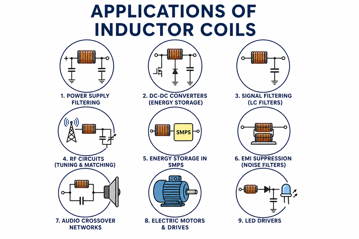
Power supplies and DC-DC converters
– Automobile Electronics
– Consumer devices
– Industrial control systems
– Communication and RF equipment
The unit of inductance is Henrys (H), which varies from nano-Henries (nH) to milli-Henries (mH).
Chapter 2. Functioning of an Inductor
An inductor works through electromagnetic induction:
– Current flows through the coil.
– A magnetic field develops around the coil.
Energy is stored within the magnetic field.
– If there is a current, there will be a magnetic field.
– The inductor produces a voltage opposing such current variations (Lenz’s Law).
Important electrical properties:
– It can withstand sudden changes in the current.
– It stores as well as releases energy.
– Smoothes out the present pulsations.
– It suppresses high frequency noise but allows DC or low frequency signals.
Key Technical Specifications
| Specification | Description | Typical Range |
|---|---|---|
| Inductance (L) | Ability to store magnetic energy; measured in henries (H), µH, mH | 1 µH – 10 mH -3 |
| DC Resistance (DCR) | Wire resistance causing power loss; lower is better | 0.01 Ω – 5 Ω -3 |
| Rated Current (Ir) | Maximum continuous current without overheating | 0.1 A – 10 A -3 |
| Q Factor (Quality) | Efficiency ratio; higher Q = lower loss | 20 – 200 -3 |
| Self-Resonant Frequency | Frequency where inductive and capacitive reactance cancel; operate below this | 1 MHz – 100 MHz -3 |
| Operating Temperature | Safe ambient and internal temperature range | -40°C to +125°C -3 |
Chapter 3. What’s inside a typical inductor coil ?
Standard inductor coils are made of several parts:
3。1) Winding (the coil
– Copper wire, often enamel-coated
– Calculates inductance, DC resistance, and maximum current values
3.2) Core material:
– Hollow magnetic core (no magnetic material)
– Ferrite core (suited for high frequency, low losses)
– Iron powder core (for larger current handling)
– Laminated steel core (Low Frequency and High Power)
3.3) Insulation & Spool
– Winds are retained stable and electrically insulated 4) Housing – Epoxy, plastic, or metal shielding for added strength and EMI protection 5) Term – Through-hole and surface-mount leads Would you like me to adjust the length and style to fit a certain number of words?
Chapter 4. Types of Inductor Coils
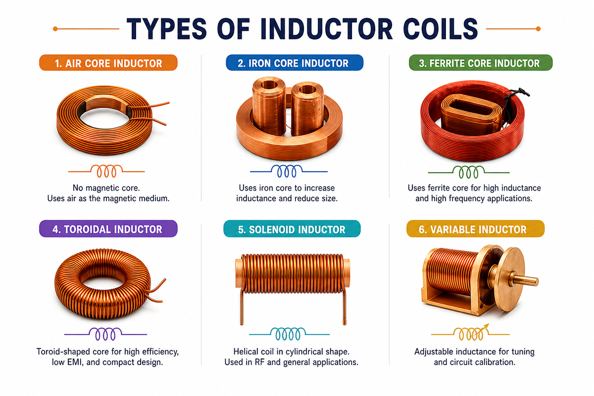
Common Types of Inductor Coil
| Type | Characteristics | Applications |
|---|---|---|
| Air Core Coil | No magnetic core; low loss; high Q factor; stable at high frequencies -4 | RF circuits, NFC antennas, wireless communication -4 |
| Ferrite Core Coil | High inductance in compact size; cost-effective -4 | Power supplies, general filtering, consumer electronics -4 |
| Toroidal Coil | Closed magnetic loop; low EMI; minimal magnetic leakage -4 | High-end audio, medical devices, precision instruments -4 |
| Bobbin Wound Coil | Wound on plastic bobbin; stable structure; easy PCB mounting -4 | LED drivers, automotive electronics, household appliances -4 |
| Choke Coil | Designed to block AC while passing DC -6 | Power supply filtering, noise suppression -1 |
nductors have a number of built-in varieties with different applications:
– Wire-Wound (By Construction)
Typical wound wire on a bobbin.
Capable of handling high currents.
Examples: chokes, power induct
– Multi-layer Ceramic (MLCC-type
Layers of ceramics with printed conductors.
Extremely low profile.
Examples : mobile devices, GHz-range circuits.
– Film / Thin-Film
Metal patterned on an substrate.
High precision with tight tolerance.
Examples: RF circuits, oscillators.
– Molded
Contained in plastic or epoxy.
Provides mechanical protection.
Examples: automotive electronics, industrial electronics.
Specialized Types:
– Common Mode Chokes: two layers for noise rejection.
– Coupled Inductors: A pair of coils share the magnetic flux path.
– Saturable Reactors: The value of inductance will vary according
– Peak Coils: These are used for pulse shaping.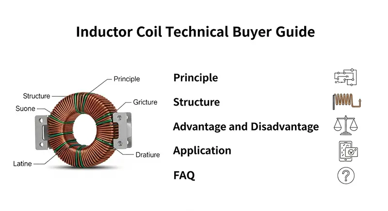
Chapter 5. Benefits of Inductor Coils
1) Storage of energy—very essential for switching regulators and power conversion.
2) EMI and Noise Suppression – Suppresses high-frequency
3) High reliability—no moving parts, long life.
4) Broad range of applications—from small low-power devices to large industrial systems.
5) Passive operation,—no external control or power required.
Chapter 6. Drawbacks and limits of Inductor coil
List of Factors Preventing Use of Capacitors:
1) Physical size—capacitors of higher induct
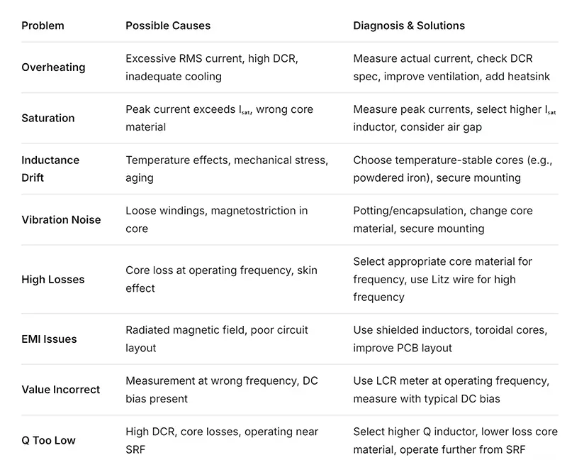
2) Too much current could saturate the inductance and give off heat.
3) Copper loss (DCR)—DC resistance.
4) EMI Leaking/Noise – Poor Design.
5) Frequency dependence—performance varies with frequency.
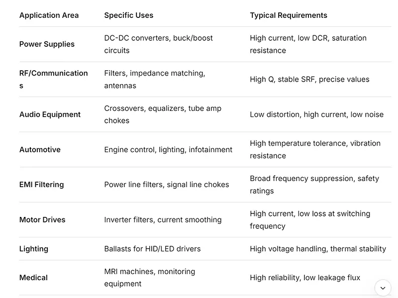
Chapter 7 .Application of Inductor Coil
8. Buyer’s Guide –Inductor Coil Selection Checklist
8.1 Important parameters to choose:
– Inductance value: target value with tolerance(±5%, ±10%, ±20%), take into account the temperature/current
– Existing requirements: RMS current for heating, Peak current to prevent saturation; Margins shall be set at 20% – 30% for safety reasons.
– Operating frequency: frequency of operation versus SRF; must keep below 80% SRF. Core material should depend on the frequency.
– DC Resistor (DCR): The efficiency (Power loss = I²R) will be affected by DC resistance. As DC resistance reduces, it leads to lower heating and
– Physical limitations: size in terms of footprint and height, and packaging type (through-hole and/or Surface-Mount Devices, SMD).
– Environmental factors: Operating temperature range, humidity levels, vibration and shock requirements, and RoHS compliance.
8.2 Common selection errors:
– Absence of saturation current in switching regulators.
– Audio frequency inductors to be used in RF.
– Failure to consider the impact of DCR on efficiency. – Inappropriate selection of the material to use as the core. – Forgetting the self-resonant –
– Underestimating thermal management. Quality indicators to look for: – Data transfer rate: DCR at 20°C, at maximal operating temperature. – SRF started under measurement conditions. – Compliant with AEC-Q200 for Automotive. – In-depth thermophysical properties. – Reliability data (MTBF, life testing).
Chapter 9. FAQ – Common Buyer Questions
Q1: Can I use a similar antenna for experimentation?
Your circuit design needs and calculations for switching frequencies.
Q2: What will happen if the inductor saturates?
The inductance decreases drastically, resulting in an increased ripple and hence overheating.
Q3: How do you define a choke compared with a power inductor?
Chokes are employed for noise reduction, and the power inductors are storage devices for energy.
Q4: Are shielded inductors better
Yes. In EMI-sensitive designs, shielded inductors reduce magnetic radiation.
Q5. Can inductors withstand high temperatures?
Yes, as long as you specify the correct core material and insulation class.
Q6: What is the difference between an inductor and a choke?
Chokes are usually inductors designed for the sole purpose of preventing higher frequency AC and allowing DC to pass. Chokes are inductors, but not all inductors are chokes.
Q7: Can I parallel inductors?
Also, canadding parallel inductors Yes, but the inductance value reduces to half when two equal inductors are connected in parallel. Make sure both share equal current.
Q8: Why inductance decreases with respect to current?
A magnetic core becomes saturated at large currents, reducing the permeability. This is absent in air core inductors.
Q9: What is the result of the self-resonant frequency (SRF)
being exceeded Beyond SRF, the inductor behaves in a capacitive manner, and this could bring instability in circuits that are not designed that way.
Q10: Can I measure LCR without using an LCR meter?
Use the signal generator, the resistor, and the oscilloscope to build the resonant circuit, or build the tank circuit with the known capacitor.
Q11: Can a higher inductance value be substituted?
Occasionally, but often substantially impacting the performance of the circuit—cutoff points in filters or the ripple current and transient responses in power supplies.
Q12: In what aspects are toroid cores preferable to others?
These form a closed magnetic path to reduce EMI. The magnetic flux is confined within the core, thus improving the magnetic efficiency.
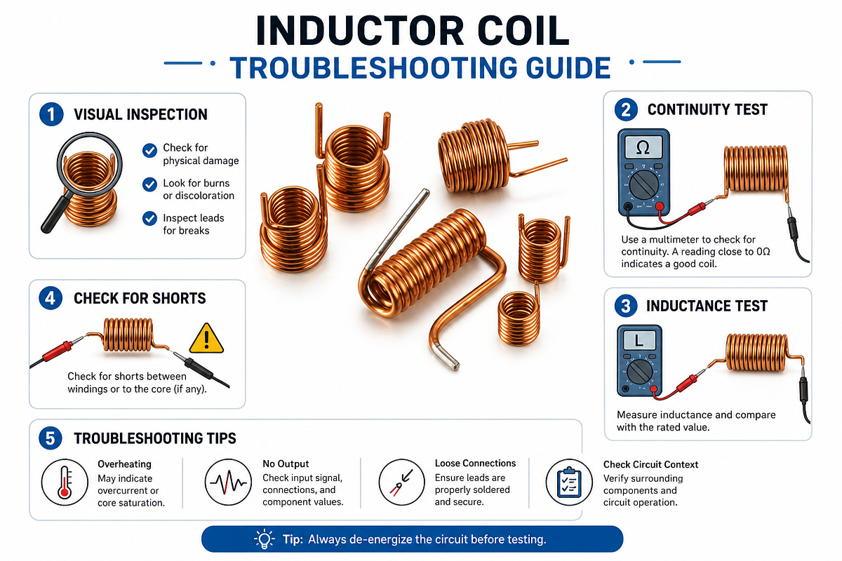
Chapter 10. Troubleshooting Guide on inductor coil
10.1 Testing Procedures:
– Visual checks: Inspect the component for visible damage or coloring that would imply overheating.
– DCR Measurement: Using a Multimeter and Comparing the Value to the Spec.
– Inductance test: It is measured using an LCR meter at a frequency used in device operation.
– Saturation test: Apply DC current and observe for decrease in inductance.
SRF measurement
Use network analyzer or impedance analyzer.
10.2 Inductor Coil Preventive Measures:
– Heat management: Ensure there is airflow and possibly a heat pad.
– Mechanical fixing: use adhesive or clamps in highly vibrating environments.
– Current Monitoring: The circuits need to be designed to keep the current well within limits.
-Derating: the force is usually operated at 70-80% of the maximum rating for improved reliabilities.
– Regular inspection: In critical applications, regular DCR tests might disclose degradation.
10.3 Inductor Coil Maintenance & Installation
– Monthly visual inspection for physical damage, cracks or corrosion
Clean quarterly with compressed air or soft brush (avoid solvents unless approved)
Check resistance twice a year with an ohmmeter, check inductance with an LCR meter
Perform insulation resistance testing annually
Instructions for installation:
Before mounting, check the specifications against circuit requirements.
Secure coil with manufacturer-supplied hardware to reduce mechanical stress
Do not bend or twist the leads too tightly as this could damage the windings.
Keep clearances as per safety standards to prevent arcing.
Chapter 11: Inductor coil Conclusion & Final Recommendations
Key takeaways:
Selecting an inductor coil requires balancing electrical requirements, physical limitations, and costs. A ‘perfect’ component does not and can not exist in reality, since all picks involve trade-offs of size, specs, and cost.
Top 5 inductor coil selection rules :
1) Existing standards: it is necessary to check both the RMS (heating) and peak (saturation)
2) Frequency awareness: Pair the material and construction techniques with the operating frequencies.
3) Its efficiency has a big impact since low DCR affects battery life and power consumption.
4) Space constraints: Establish boundaries as they also define possibilities.
5) Test in application – bench test under actual working conditions.
Who to see and when:
– Needs of custom inductor
– High frequency RF: (> 100 MHz)
– Harsh environments (high temperatures, radiation, vacuum)
– Safe-critical systems (med., aeron
– When standard parts do not meet requirements
– Integration: Use of inductors on PCBs or packages
– Higher Frequency Range: Material suitable for MHz/GHz Power Conversion
– Miniaturization: nano-materials and 3D printing for micro-ind
– Smart inductors: Temperature and current measurement
– Using sustainable materials: recyclable and with low environmental impact
Final Inductor Coil checklist before purchase:
– Verify the inductance value at the operation frequency with the anticipated DC bias.
– Ensure the saturation current is greater than the maximum peak current – Evaluate DCR effect on Circuit Efficiency – Ensure that SR F is well above the operating frequency – Validate if actual physical dimensions match with available space – Test thermal performance in the designed environment – Check for required certifications such as AEC-Q200, UL, – Verify availability and times for production
Please remember that there is limit standardization when it comes to inductors, as there is, say, regarding resistors or capacitors. You might want to seriously consider affiliating yourself with a reputable supplier or manufacturer and getting good tech support. Or, if there’s any doubt, request samples and test them thoroughly under real-world conditions, thus creating knowledge for future projects.