Solenoid valve selection goes beyond matching voltage and piping size. You have to consider compatibility with the medium, pressure, temperature, flow, availability of electricity, operation frequency, environment of installation, and valve movement.
Solenoid valve selection will improve reliability, speed of operation, energy efficiency, and lifespan of the equipment. Selecting a solenoid valve by price and one specification can lead to leaking, overheating, slow operation, premature failure, or even a hazard.
This guide will explain what a solenoid valve is and how the solenoid valve works, common valve terminology, and how to select the right solenoid valve.
Chapter 1: What is a solenoid valve
A solenoid valve is an electrically actuated valve to start, stop, direct, or regulate the flow of fluids and gases.
The principle of operation is relatively simple: voltage supplied to a coil creates electromagnetic force, which moves the plunger/valve element.
It can be thought of as an automatic version of a manual valve—rather than turning a handle manually, voltage is supplied by a control system (usually a PLC).
The typical sequence of operation is
The control system supplies voltage to the solenoid coil.
The coil generates a magnetic field.
A magnetic field attracts a movable plunger or armature.
The plunger moves to a new position.
The flow path is opened, closed, or changed.
The plunger goes back to its initial position upon loss of power by a spring, pressure differential, or other means.
Even though solenoid valves are simple in construction, they play a key role in the automation of many processes.
Some of the industrial applications for solenoid valves include:
Automation equipment, pneumatic
Packaging machinery
Manufacturing line
Robots industry
Dispensing and Washing Equipment
Water treatment systems
HVAC equipment
Medical and analytical equipment
Vehicle systems
Process control devices
Fluid and Gas Systems
Often the solenoid valve acts as an interface between the electrical control system and the mechanical/fluid-powered actuator.
1.1 Motorized Valve vs. Solenoid Valve
Many people confuse these two devices, but they are used for different purposes.
Electromagnetic force is used either directly or indirectly (by a pilot mechanism) to move the valve element of the solenoid valve. It works best in case of quick switching and control of direction.
A motorized valve is operated by an electric motor and mechanical transmission. It is slower but offers more control of valve position and flow.
So the question is:
Do you need to make a quick switch or continuous flow adjustment?
A solenoid valve is usually a better choice for quick switching and controlling the direction of pneumatic flow. When proportional or position-based flow control is needed, a motorized valve would be a better choice.
Chapter 2: Solenoid Valve Terminology: Understanding Ways and Positions
When choosing a solenoid valve, you will often come across terms like 2/2-way, 3/2-way, 5/2-way, and 5/3-way valves.
Those numbers show how many positions and how many fluid ports (or flow connections) a valve has.
2.1 What Is “Position”?
The first number indicates the number of positions of the valve.
For example,
2/2-position valve: two positions of spool
3-position valve: three positions of spool
A 2-position valve can be compared with a simple electrical switch—it has two operational states.
A 3-position valve has three positions, including one central position. The function of the central position varies from one design to another.
Common central positions are
Closed circuit
Hub exhaust
Center of pressure
These positions define what happens to the actuator when the valve is in its central position.
2.2 What Is “Way”?
The second number shows how many fluid ports or flow connections a valve has.
Eg.
2-way valve – 2 ports
Three ports: 3-way valve
Five ports: 5-way valve
These two numbers provide basic characteristics of the valve.
2/2-Way Solenoid Valves
2/2-way valve has:
Two jobs
Two ports
It is usually used for simple switching of fluid or gas on and off.
It can be, depending on the design:
Normally closed (NC)
Normally open (NO)
Normally, a closed valve opens when energized and closes when not energized.
Reversed applies to the normally open valve.
3/2-Way Solenoid Valve
3/2-way valve has:
Three-port
Two positions
It is commonly used for control of single-acting pneumatic cylinders.
Ports are as follows:
P = supply pressure;
A = actor;
R = exhaust”
One position connects P with A, while another connects A with R.
5/2-Way Solenoid Valve
5/2-way valve has:
Five ports.
Two positions
It is commonly used for control of double-acting pneumatic cylinders.
Ports are as follows:
P = supply pressure;
Actor ports: A and B;
R and S = exhaust outlets
One position provides pressure supply to A while venting B; another changes the direction.
Solenoid Valve – 5/3 Way
5/3-way valve has:
Five ports
Three positions
The central position can be changed according to the application, e.g.
-Closed center
Hub exhaust
Center of pressure
This type of valve is useful when a pneumatic actuator requires a specific condition during the standby state.
2.3 How to Interpret Pneumatic Valve Symbol
General rule:
Number of boxes = number of positions; number of ports is shown in the valve symbol.
An arrow shows a flow path, and a blocked symbol shows a blocked passage.
In spring-return valves, the symbol near the spring indicates the position of the valve when it is not energized.
Once you learn those symbols, it will become much easier to cross-reference valve configurations before buying.
Chapter 3: solenoid valves Working principles and main types
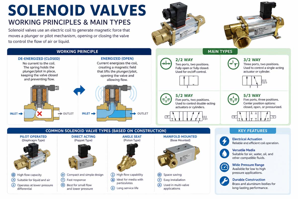
Solenoid valves can be classified in many ways. Two of the most significant classifications are
Direct Acting vs. Pilot Operated
Single solenoid vs. double solenoid
This classification has to be taken into account during the selection process.
3.1 Solenoid Direct-Acting Valves
In a direct-acting solenoid valve, the valve element is moved directly by electromagnetic force.
When energized, the magnetic field pulls the plunger or armature, opening or closing the flow path.
Benefits:
Simple construction
Fast response
Reliable operation
Works without minimum pressure differential
Best for low-flow applications
Constraints:
Fluid pressure and spring force have to be overcome by electromagnetic force directly. That is why for bigger valves or orifices, stronger electromagnetic force is needed.
Usually used for direct-acting valves
Low flow rates
Low-pressure systems
Smaller machines
Specific switching applications
Applications without differential pressure
3.2 Pilot-Operated Solenoid Valve
The pilot-operated valves use the pressure of the working medium to assist in operating the valve.
The solenoid does not move the large main valve element directly by electromagnetic force but operates the small pilot passage, while the pressure differential moves the main diaphragm or piston.
This principle allows a relatively small solenoid coil to control a large flow passage.
Benefits:
Lower requirements to electromagnetic force
For larger openings
Higher flow capacity
Power consumption reduction in many designs
Appropriate for high-pressure operations
Limitations:
Pilot-operated valves usually require minimum differential pressure for correct operation.
That is why you have to always check the pressure range offered by the manufacturer.
Too low system pressure can cause improper opening or closing of the valve.
Important Selection Note
Don’t think that pilot-operated valve is better than direct-acting one.
A direct-acting valve may be a better choice for applications with low pressure or operation at zero differential pressure.
Chapter 4: Single Solenoid Valve Versus Double Solenoid Valve
Another difference is in the number of solenoids and how the solenoid valve works with power off.
4.1 Single Solenoid Valve
One solenoid valve normally operates as follows:
Activated -> valve shifts
De-energized -> valve returns to
Return spring is normally used as the return mechanism.
It brings an important safety aspect of the valve—if the electrical signal is removed, the valve will automatically go to a defined position.
When to use single-solenoid valves
Should be able to automatically return to position
The fail-safe operation is an important point here.
The actuator should return when losing power.
The control system uses simple ON/OFF signals.
4.2 Double Solenoid Valve (DSV)
In the case of a double solenoid valve, two solenoids control two positions of the valve.
In pneumatic circuits, activating one solenoid shifts the valve to one position, and activation of another solenoid shifts it to another position.
Some DSV valves are built as bistable valves so that they remain in their last position once the electrical signal is removed.
This could be useful in cases when the system needs to maintain the valve state without constantly powering the coil.
Safety Consideration (Important Note)
Do not assume that the double solenoid valve would always produce a mechanically locked actuator position once the power is lost.
The actual behavior will depend on the valve design, pneumatic circuit, actuator, air leaks, and loads.
In the cases when a machine needs to maintain a load safely after the power is lost, the whole safety function should be designed using appropriate mechanical and/or pneumatic means, rather than relying on the valve spool position alone.
Chapter 5: 7 Tips on Solenoid Valve Selection
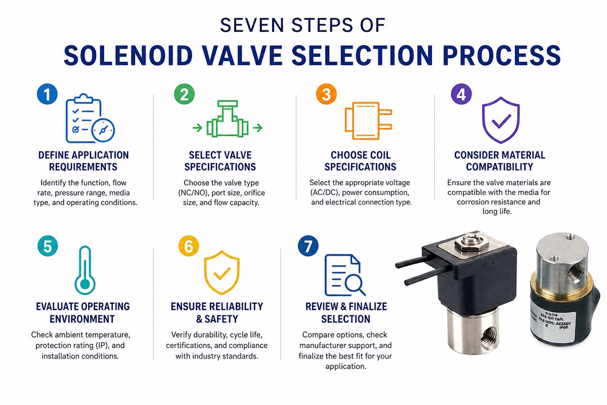
Now we are getting to the most important point—how to select the correct solenoid valve for a particular application.
Develop your application in a systematic manner—do not choose a valve based on a particular parameter.
The proper selection process is as follows:
Medium -> Pressure -> Temperature -> Flow -> Function -> Electrical Requirements -> Environment
5.1 Step 1. Determine the Working Medium
Ask yourself first: •
What is running through the valve?
The medium can be:
Compressed air, water, oil
Steam Suction
Gas Refrigerant
Corrosive substances.
Pharmaceutical or food liquids
The medium defines the proper valve body, diaphragm, seal, and internals.
For example, a valve designed to operate with compressed air cannot be automatically assumed to be suitable for hot water, steam, or aggressive chemicals.
Check out these parameters.
Medium type
Chemical compatibility
Gas or liquid.
Cleanliness
Presence of particles
Viscosity
Corrosiveness
Lubrication needs
In case the medium is contaminated with particles, filtration may be required to prevent valve seat and moving part contamination.
5.2 Step 2. Check Pressure and Differential Pressure
Pressure is one of the key parameters in the selection process.
Check out:
Minimum operating pressure
Maximum operating pressure
Inlet pressure
Outlet pressure
Differential pressure
The minimum differential pressure is especially important for the pilot-operated valves.
For example, if the valve needs to have a minimum differential pressure in order to operate and the system pressure drops below that pressure value, the valve will not operate correctly.
Never choose a valve based on its maximum pressure rating only. The lowest pressure rating is just as important.
5.3 Step 3. Identify Electrical Requirements
Now let’s define the control mode of the valve.
Typical voltages of the solenoids are as follows:
12 V DC, 24 V DC, 24 V AC, 110 V AC, 120 V AC, 220 to 230 V AC
The 24 VDC voltage is very common in industrial automation, and it is easy to integrate it into a PLC control system.
Check also:
Power consumption of the coil
Current use
Duty cycle
Electrical connections
Surge protection
Insulation class
Control output requirements
For a DC coil of a simple type:
Current ≈ Power / Voltage
For example, a 24 VDC coil with 6 W of power will consume 0.25 A on nominal operation.
The PLC output or relay should be able to drive an electrical load.
5.4 Step 4. Selecting Solenoid Valve Function and Flow Capacity
Now once the medium, pressure, and electrical requirements are known, let’s define what the valve needs to do.
The typical functions are
Basic ON/OFF control
Single-acting cylinder operation
Two-position cylinder control
Change in flow direction
Exhaust handling
Vacuum control
Intermediary actuator position
Then select the proper configuration:
2/2-way
3/2 way
5/2-way
5/3 Way
Careful about the flow capacity!
Valve performance is not limited to pipe sizes.
The flow capacity is commonly described with such parameters as
CV 1
KV
Flow rating
Effective area
The system is not necessarily better with bigger sizes. The valve needs to be selected with the proper flow and pressure.
In pneumatic systems, the flow capacity may be insufficient for the following situations:
Slow movement of cylinders
Poor actuator performance
Increased cycle time
Pressure drops
Hence, the valve needs to be chosen for the required flow, not just for pipe size.
5.5 Step 5. Verify Response Time and Frequency of Operation
Some applications need very fast switching.
For example:
PACKAGING MACHINERY
Pick & place machines
Blow-off systems
Sorting machines
Vending Machines (single)
Pneumatic controls, high frequency
The key parameters here are
Response time for opening
Response time for closing
Maximum switching frequency
Duty cycle
Service Life (expected)
The valve performing well at low frequencies may not be appropriate for high-frequency operations.
If the machine is cycled hundreds of thousands or millions of times, check the valve lifetime under the conditions as close to the real use as possible.
5.6 Step 6. Consider the Installation Environment
The environmental conditions may significantly affect the valve reliability.
Check the following:
Ambient temperature
Make sure the valve and coil have the proper ratings for the temperature range.
Exposure to water and humidity
If the valve will be exposed to water, condensate, and wash-down, make sure to choose the proper enclosure and connector protection level.
Dust
The industrial dusty environment may require additional protection from contamination.
Vibration
High vibration may influence electrical connections and mechanical parts.
Corrosive environment
Corrosion-resistant material or coatings may be needed in the case of coastal and chemical industry environments.
Hazards (classified locations)
If the equipment is going to be installed in an explosive atmosphere, the valve and electrical parts should have the proper hazardous location certifications.
Don’t use the regular solenoid coil in a hazardous location just because its voltage is equal to the control system.
5.7 Step 7. Evaluate Quality, Cost, and Special Features
Price and brand name are supposed to be the main selection factors only after defining the technical requirements.
Key considerations:
Product quality
Dependability
Life Certifications
Technical support
Availability
Spares.
Delivery time
Ownership cost
The following special features may be useful depending on the application:
Manual override.
Indicator light
Surge protection:
DIN plug
Cable hookup
Low-power coil
High-temp coil
Corrosion-resistant housing
Explosion-Proof, Coil
Custom mount configuration
The cheapest valve is not necessarily the least costly option.
A failing valve may become an expensive problem, causing machine downtime, maintenance costs, defective products, and emergency replacements.
Chapter 6: Solenoid Valve Selection Project Examples Case
Let’s consider the selection process for some typical applications.
Example 1. Production Line Pneumatic Stopper Cylinder Application
Using a pneumatic cylinder to stop products on the conveyor.
Requirements:
Compressed air
Operating pressure is about 0.5 to 0.6 MPa.
PLC control 24 VDC
The cylinder should return when de-energized
Frequent operation
Environment of factory – industrial
Suggested approach
The valve with automatic return and spring should be used in this case.
In the case of a single-acting cylinder, a 3/2-way valve may be used.
The valve flow capacity should match the cylinder size and the speed of its operation.
Typically, the regular industrial valve with proper sealing material and protection against the environment would be enough.
Example 2. Robotic Gripper, which should Maintain Its State
The robotic gripper maintains a workpiece. It is important for the system that the gripper remains in a defined state in case of losing a control signal.
Selection consideration:
If it is necessary to maintain the last commanded position of the valve, the double solenoid valve may be considered.
However, it does not mean the mechanical locking of the gripper.
In case of suspending or critical safety loads, additional measures should be taken, such as
Mechanical Lock
Pilot Operated Backflow Preventer
Rod Lockout
Pressure-Maintaining Loop
Pneumatic Circuit Safety Ratings
The proper solution is a function of load, actuator design, failure modes, and machine safety requirements.
Chapter 7: How to Avoid the Common Installation and Maintenance Mistakes
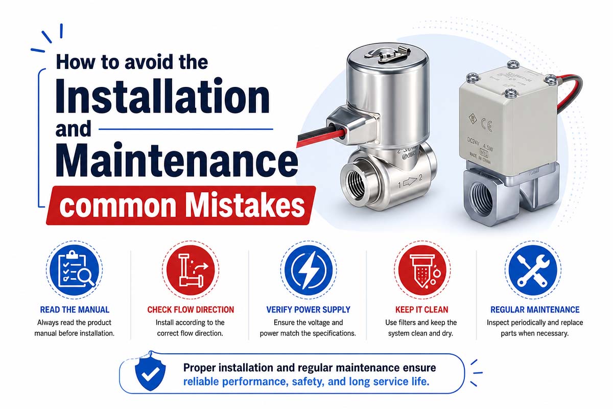
Choosing the right valve is only the beginning. Longevity depends on how the valve is installed and maintained.
7.1 Check flow direction
Always take into account the manufacturer’s indication regarding flow direction.
Otherwise, the valve won’t work properly.
7.2 Avoidance of Pipe Stress
Avoid using hard tubing that puts excessive mechanical loads on the valve.
Vibrations and joint failure can be prevented if the pipe is installed correctly.
7.3 Maintain cleanliness of the medium
If it is a pneumatic system, use proper filters before the valve.
Contamination can lead to the following problems:
valve jamming
internal leakage
response delay
seat damage
premature tire wear
7.4 Working within the Correct Pressure Range
It is important to operate the valve within this pressure range in order to prevent improper functioning and decrease the lifetime of valve components.
7.5 Check coil voltage
Do not connect the 24 VDC coil to 110 VAC or 220 VAC.
Moreover, don’t think that coils with the same nominal voltage have the same characteristics.
7.6 Take water hammer into account.
When it comes to liquids, one should be cautious with rapid flow stops. They can cause pressure spikes (water hammer).
In case it is necessary, consider the following solutions:
valves that close slower
flow control
pressure relief
accumulators or dampers
correct piping design
Chapter 8: Common Solenoid Valve Problems and Troubleshooting
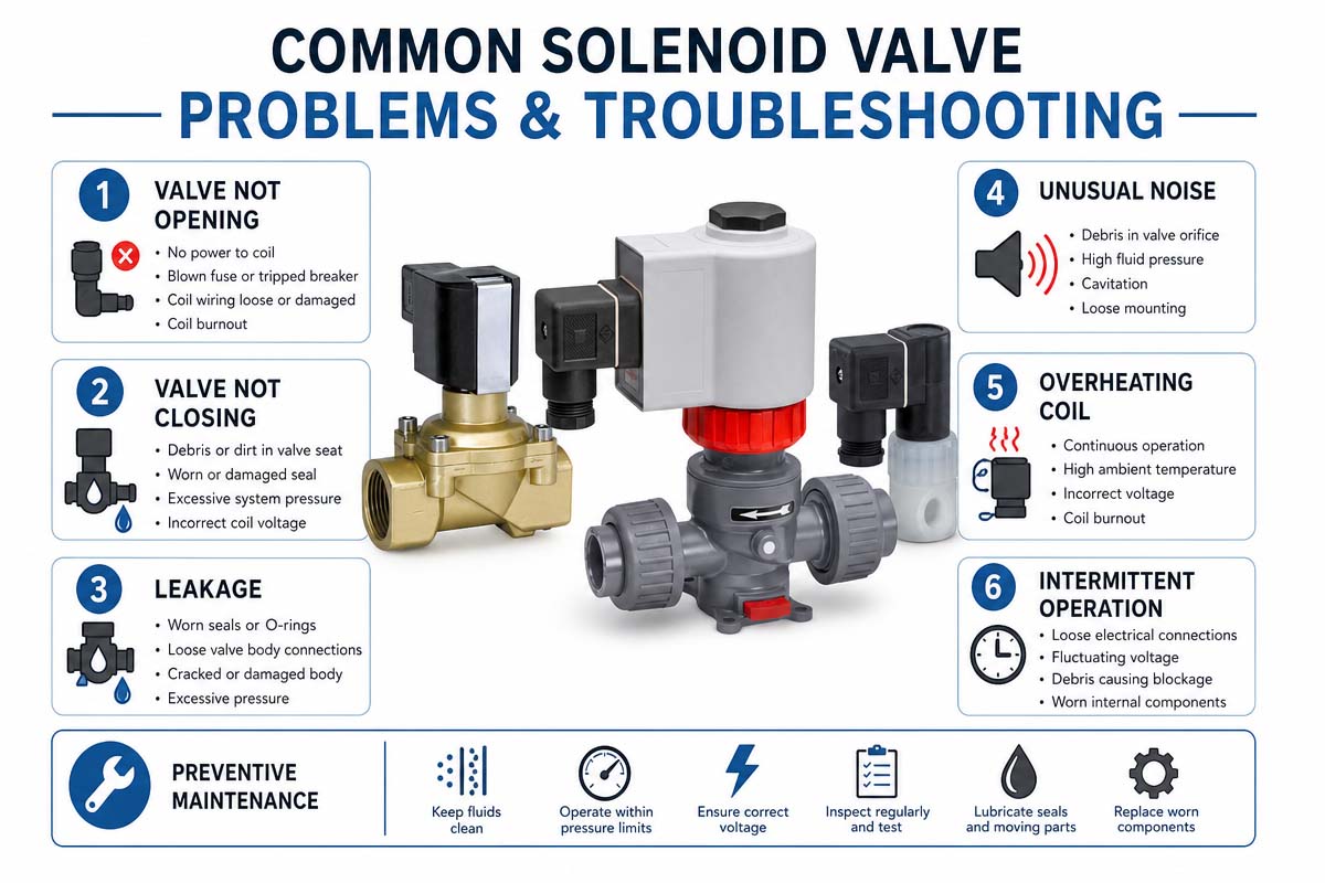
Even a carefully selected valve can face difficulties due to incorrect installation or maintenance.
Problem 1: Valve does not work. Check: Is the correct voltage applied to the coil?
Is the coil broken?
Is the connector connected properly?
Is the pressure in the range?
Are the valve spool and plunger clean?
The valve is installed correctly.
Make sure that the pressure difference in the case of pilot-operated valves is correct.
Problem 2: The valve works, but there is no flow.
The possible causes are
incorrect port connections
filter blockage
insufficient pressure
contamination
incorrect valve design
broken diaphragm or seals
Problem 3: The valve does not close completely.
The possible causes are
dirt or particles in the valve seat
damaged seal components
excessive pressure
incorrect installation
worn internal parts
Cleaning or replacing is required.
Problem 4: The coil is overheated.
A certain increase in the coil temperature during the operation is normal.
Nevertheless, overheating may indicate the following problems:
The voltage supply is wrong.
incorrect coil parameters
too high switching frequency.
wrong duty cycle
mechanical problems leading to improper operation
incorrect heat dissipation
electrical problems
Compare the actual operating conditions to the manufacturer’s specifications.
Checklist for Choosing a Solenoid Valve
Please provide the following information before placing your order:
Medium: Air, water, oil, steam, gas, chemicals, etc.
Medium Temperature: min/max
Operating Pressure: min & max
Differential pressure: min and max
Required Flow Rate: Cv, Kv, or equivalent
Port size: 1/8″, 1/4″, 3/8″, 1/2″, etc…
Function of valve: 2/2, 3/2, 5/2, 5/3, etc.
Normal State: open or closed
Actuator: single- or double-acting
Coil Voltage: 12V DC, 24V DC, 110V AC, 230V AC, etc.
Power Consumption in W or VA
Response Time: It Matters
Switching Frequency: cycles/second/hr
Duty Cycle: Continuous or Intermittent.
Ambient Temperature
IP protection
Corrosion Resistance
Hazardous Area Requirements
Connectors, Electrical
Lifetime Needed
Certifications
Space Available
Expected volume and budget
Knowing all the required specifications makes communicating with the solenoid valve manufacturer easy.
Chapter 10: Conclusion on Solenoid Valve Selection
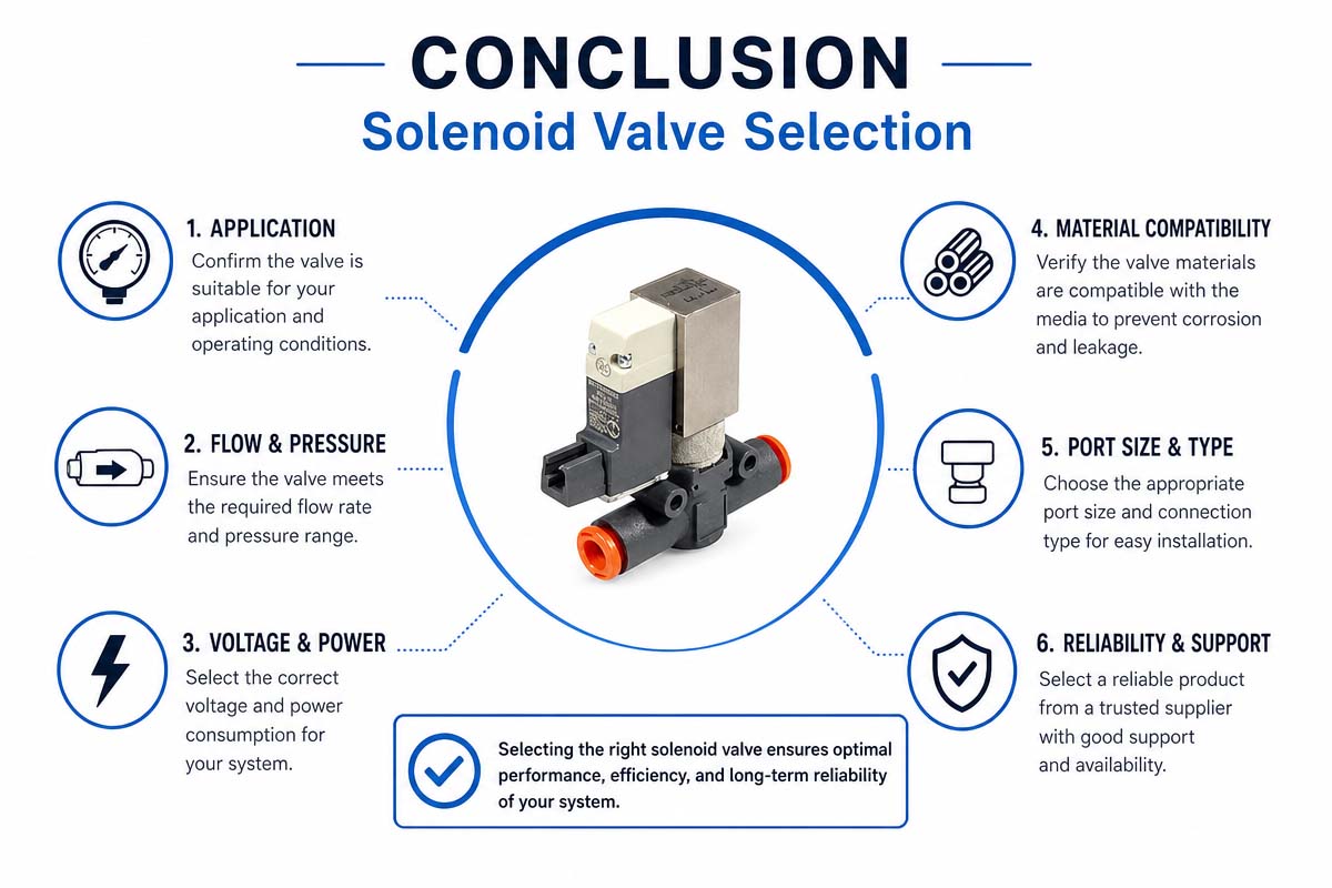
At first glance, the solenoid valve selection can seem quite complicated with so many different parameters provided by manufacturers. Nevertheless, if the logical sequence is followed, everything becomes easier.
Start with the medium, then the pressure and temperature. Determine the required flow capacity and valve function. Next, check coil voltage, power, duty cycle, response time, environmental conditions, and lifetime required.
The basic rule is
Never choose a solenoid valve according to the voltage and port size only. Choose it according to the whole range of operating conditions of the application.
A properly selected solenoid valve provides fast response, reliable switching, long life, and smooth operation of the machine. Moreover, it prevents unnecessary downtime and breakdowns.
An off-the-shelf valve is enough for most of the applications. Nevertheless, when an application requires unusual dimensions, high temperatures, special pressures, limited installation space, custom electrical connections, extreme life cycles, or particular flow-force requirements, direct cooperation with a professional solenoid valve manufacturer can be a better solution.
The best valve is not always the biggest, cheapest, or strongest. It is the valve that has the same electrical, mechanical, fluid, and environmental parameters as the actual ones of the application.