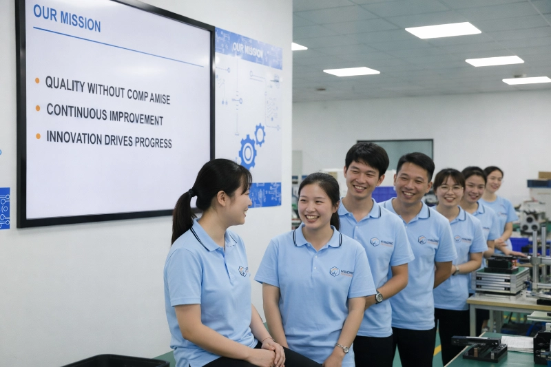
As a company operating under the Weilong brand, we adhere to the tenets of proactive quality management and open and clear communication. This guide will cover some of the typical difficulties and corresponding ways of dealing with them associated with plastic injection and metal stamping.
Related guides: PLASTIC INJECTION MOLDING: FAQ & Trouble shooting.
Chapter 1: Common Defects & Solutions
1.1 Sink Marks & Voids
Issue: Depressions or hollows in the part surface
Causes: Packing pressure is insufficient
Low cooling time
Thick sections cooling unevenly
Material shrinkage problems
Our Solutions:
- Optimize the packing pressure and time
- Enhance cooling time
- Gate modification: location/size
- Adjust wall thickness uniformity
- Use lower shrinkage materials
1.2 Warpage & Distortion
Problem: Part warps after e
Causes:
Uneven cooling
Differential Shrinkage
Residual stress
Too early ejection
Our Solutions:
- Optimize cooling channel design.
- Equalize mold temperatures.
- Adjust packing parameters.
- Maintain equal wall thickness.
- Use stress relief annealing.
1.3 Short Shots (Incomplete Fill)
Problem: The mold is not filling up completely.
Causes:
Low injection pressure.
The material temperature is too low.
Venting is insufficient.
Gates: Gates are small in
Our Solutions:
- Increase injection pressure and speed.
- Increase melt and mold temperatures.
- Improve venting.
- Expand gates or runners.
1.4 Opt for high-flow materials.
Flash (Burrs
Problem: Excess material at the parting line.
Causes:Excessive injection pressure.
The force of clamping is not adequate
The tooling is worn.
Mold alignment is disrupted.
Our Solutions:
- Reduced injection pressure.
- Increase clamp-tonnage force.
- Tooling Repair and Maintenance.
- Enhance the mold maintenance schedule.
1.5 Weld Lines
Problem: Where the melt-fronts meet, there are visible lines.
Causes:
Several gates.
Flow path obstructions.
Lack of melt temperature.
Injection rate, which is preferably
Our Solutions:
- Optimize gate placement.
- Raise melt temperature.
- Boost the speed of the injection
1.6 Modify design of parts to reduce flow barriers.
Burn Marks (Diesel Effect)
Problem: Black or brown marks disfigure the surface of the part.
Causes:
Trapped air.
Excessive shear heating.
Material Composition.
Inadequate ventilation
Our Solutions:
- Enhance Venting
- Lower injection rate
- Lower melt temperature
- Clean and maintain tooling
Chapter 2: FAQ
Q1: What is the method used in calculating the optimal wall thickness of a plastic product?
NH: Follow industry norms: 0.5-4.0mm based on material and product size. Flow analysis is used to optimize parts for equal filling and eliminate sink marks. Engineers´ suggestions are provided through DFM analysis.
Q2: What are the causes of inconsistent part dimensions?
A: These could include: Inconsistent material properties, Mold temperature variances, Incorrect machine parameters, Tooling damage. B: We follow SPC, Ensure process parameters are consistent, Regular maintenance of the mold is done.
Q3: How do you handle material degradation problems?
A: Residence time of the material, proper drying procedures, proper melt temperatures, and proper purging schedules are taken into consideration by us.
Q4: What is your method for gate vestige minimization?
A: Precision gate design, optimized gate size and location, the use of hot runner technology where appropriate, and, in some cases, secondary operations may be employed.
Q5: How do you handle color matching challenges?
A: We only work with accredited color material sources, keep tight control over inventory, use calibrated color-measuring equipment, and carry out batch-to-batch verification processes.
Q6: Why are there black specks in plastic components?
A: Normally due to material degradation, contaminated regrind, or equipment/tooling contamination. It is prevented by taking appropriate purging methods and ensuring a clean environment during the process.

Chapter 3: METAL STAMPING: FAQs & Trouble shooting Guide
Frequently encountered defects & solutions
3.1 Burrs & Sharp Edges
Problem: Roughness in cutting or blanking operation residues.
Purpose
Causes:
Worn tooling
Incorrect clearance.
Dull cutting edges.
Material springback.
Our Solutions:
- Sharpening and Maintenance of Tools.
- Punch-Die Clearance Optimization.
- Applying tooling coatings.
- The application of the fine blanking process whenever it
3.2 Springback Issues
Problem: Component also doesn’t retain its formed shape.
Causes:
Material memory.
Lack of sufficient forming pressure.
Wrong bend radius.
Material variations.
Our Solutions:
Overbend Compensation
Bottoming operations
Using Forming Pads
Material property consistency control is a Cracking and Splitting Problem
Material cracks during forming
Causes:
Excessive Deformation
3.3 Material too hard/brittle
Improper Grain Direction
Lack of adequate bend radius
Our Solutions:
- Increased bend radii
- Use annealed materials.
- Optimize Grain Direction
- Use multi-stage forming
3.4 Wrinkling & Buckling
Problem: Material wrinkles during drawing/forming
Causes:
Not enough blank holder pressure is acting on
Excessive Material Flow
When
Improper Lubric
Irregular Pressure Distribution
Our Solutions:
Optimize Blank Holder Pressure
Ensure
Use draw beads.
Improve lubrication.
Change tooling radii.
3.5 Surface Scratches & Galling
Problem: Scratches on finished components.
Causes
Dirty tooling.
Insufficient lubrication
Tooling surface roughness.
Material pickup
Our Solutions:
Keep tools clean and polished.
Optimize lubricant application.
Apply tool coatings (DLC, TiN, etc.).
3.6 Apply protective films.
Dimensional Incons
Problem: Variation of part dimensions.
Causes:
Tool wear.
Variation of material thickness.
Machine deflection.
– Temperature variations.
Our Solutions:
Regular tool maintenance
Material thickness monitoring
Machine calibration
Process parameter optimization
Chapter 4: Metal Stamping FAQ
Q1: What is the tool wear management process in mass production?
A: We use high-quality tool steels, perform preventive maintenance, use wear-resistant coatings, track production levels, and perform periodic inspections with precise measuring equipment.
Q2: Inconsistent hole locations in stamped components are caused by what?
A: Often caused by tooling deflection, misalignment, or material transportation. We utilize precision-guided tooling, press alignment, appropriate material handling, and sensors in order to verify position.
Q3: What methods do you use to address the thinning of the material in the deep-drawn components
A: Our strategy involves optimizing draw ratio values, employing adequate lubrication, adopting multi-stage processing and annealing where and when necessary, and computer simulation on excessive thinning processes through software programs.
Q4: How do you reduce burr formation?
A: We keep our cutting edges keen, punch and die clearance optimized (usually around 5 to 10% of material thickness), utilize fine blanking for critical edges, and often incorporate secondary deburrying.
Q5: How do you compensate for springback?
A: Experience based compensation factors, FEA simulation, validation of prototype tooling, and possibly coinming or bottomming to reduce the springback.
Q6: Why does galling occur in stainless steel stamping?
A: Usually due to material adhesion to the tooling. We employ smooth tooling surface finishing, specific lubrication, tooling coating (for example, DLC and TiN), and sometimes cleaning of the tools on a scheduled basis.
Chapter 5: ROOT CAUSE ANALYSIS procedure
Our 8 Step Problem-Solving Process
5.1 Problem Definition: Formulate the problem definition, supported by data.
5.2 Containment: Initial measures to prevent the aggravation of the situation.
5.3 Data Collection: Compile relevant process and inspection data.
5.4 Root Cause Identification: Use fish bone diagrams and other root cause tools like the five why’s method.
5.5 Corrective Action Planning corrective action planning The formulation and implementation of required corrective measures.
5.6 Verification: Validate the effectiveness of the corrective steps.
5.7 Preventive Measures: Implemented measures to prevent such cases from taking place in the future.
5.8 Documentation: All documentation has to be maintained.
Chapter 6: WARRANTY & RESOLUTION COMMITMENT
6.1 Our Quality Guarantee
Zero Defect
Aim: Becoming perfect in each aspect
Rapid Response: Initial response within 24 hours to quality-related issues
Comprehensive Support:
Technical support during resolution
6.2 Continuous Improvement
Learning from Every Challenge Resolution Timeline Critical Issues: Immediate containment, 48-hour root cause analysis In raising this complaint, there are major issues that are discussed in this Minor Problems: 5-Day Solution with Preventive Plans Trend Issues: Weekly monitoring and monthly improvement reviews TECHNICAL SUPPORT RESOURCES Services Offered by Other Parties On-Site Assistance: Engineering support at your facility Technical Training
Process and quality system training Analytical Services: Material and failure analysis Process Optimization: Continuous Improvement Programs Documentation Support Quality Manuals:-documentation Processum Complete Control Plans: Documentation of Process Control
6.3 Control Inspection Reports:
Full inspection records Material Certifications: Fully traceable materials PREVENTIVE MAINTEN Tooling Maintenance Regular Honing: Based on production numbers Surface Refurbishment: Periodic polishing and coating Component Replacement: Preventive replacement of wear items <Alignment_Validation>
Alignment Equipment Maintenance Preventive Schedules: Manufacturer Calibration Programs: Equipment Calibration Performance Monitoring: Continuous equipment performance monitoring Upgrade Programs: Technology Upgrades
Chapter 7: Conclusion: Our commitment to Quality Excellent
At Weilong we believe that each quality issues challenge is a chance to improve. By incorporating technical knowledge, methodical issue resolution, and cooperation with our customers, the success your manufacturing process needs is achieved.
Our Quality Promise: Proactive Prevention: Anticipating and preventing issues before they happen Rapid Resolution: Fast and efficient resolution of any quality concern that arises.
Transparency in Communication: Transparency in communication is essential because it allows for open and honest Continuous Improvement
Learning and improving from every experience Partnership Approach
Working together for mutual success Whether you have issues on hand or would like to proactively avoid problems, our tech experts are ready to help you succeed.