Chapter 1: Introduction of Application Practice Analysis of Push-Pull Solenoid in Attendance Devices
With the improvement of digitalization and intelligence in enterprise management, attendance devices have evolved from early mechanical time clocks to intelligent terminals integrating card swiping, fingerprint recognition, face recognition, and networked management. In these devices, in addition to the identification and control systems,Push-Pull Solenoid, as key executive components, are widely used in functional modules such as card locking, releasing, positioning, and mechanism switching. This article will systematically analyze the practical application of push-pull solenoids in attendance devices from an engineering perspective, supplement core advantages, disadvantages, and common problem solutions, providing comprehensive references for relevant engineering practices.
Chapter 2: Scenario Requirements: Core Demands for Actuators in Attendance Devices
Attendance devices are usually deployed in high-frequency usage places such as office buildings, factories, and schools. Their actuators need to meet the following typical requirements:
Fast action and timely response: User attendance actions are frequent, and processes such as card insertion, reading, and releasing must be completed quickly to avoid queuing and jamming, usually requiring millisecond-level response speed;
Accurate and repeatable actions: Push-pull actions need to be precisely in place, with stroke deviation controlled at the millimeter level, to prevent incomplete card locking or failure to pop out normally, ensuring a smooth user attendance experience;
High-frequency use and long service life: An attendance machine may be used hundreds or even thousands of times a day, and needs to support tens of thousands of action cycles during its entire life cycle. The actuator must have high durability and fatigue resistance;
Compact structure and easy integration: Attendance terminals have limited volume and compact internal space, requiring actuators to be small in size and flexible in installation methods to adapt to modular design;
Low noise and safety: Office, campus and other environments are sensitive to noise, so the working noise of the actuator must be controlled within a reasonable range; at the same time, in the event of power failure or equipment abnormality, the mechanism should automatically return to a safe state (such as releasing the card) to avoid user card retention.
Under these comprehensive requirements, push-pull solenoids, with their advantages of linear output, simple structure, fast response, and controllable cost, have become an ideal executive solution for attendance devices.
Chapter 3 : Solution Design—Selection and Functional Configuration of Push-Pull Solenoid
In the solution design stage, push-pull solenoid need to be selectively selected and configured according to the attendance method of the attendance device (such as IC card, magnetic card, fingerprint-linked mechanical structure) and mechanism functions to ensure perfect adaptation to the entire machine system.
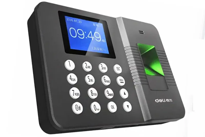
Chapter 4: Typical Application Positions
Locking and releasing after IC card/magnetic card insertion: After the card is inserted in place, the solenoid pushes the bolt to lock the card to prevent the card from shifting during reading; after reading is completed, the solenoid acts in the reverse direction to release the bolt, and ejects the card with the cooperation of a spring;
Ejection mechanism after card reading: Directly drive the ejection push rod to quickly and smoothly eject the read card, ensuring that the user can easily take the card;
Limit control for anti-misinsertion and anti-reverse insertion: Realize the expansion and contraction of the limit block through the push-pull action of the solenoid, only allowing the card to be inserted correctly in the forward direction, avoiding damage to internal mechanisms caused by misinsertion;
Mechanical anti-disassembly or anti-cheating structure: In some high-end attendance devices, solenoids are used to drive anti-disassembly pins. When the device is illegally disassembled, the solenoid is de-energized and released, triggering an alarm signal and locking core functions.
Chapter 5: Selection of Push-pull Solenoid Types
5.1 Core type: push-pull solenoid are mostly used. Their linear push-pull actions are stable, and the control logic is simple. Action switching can be achieved only through power on/off, which is easy to integrate with the main control board;
5.2 Reset design: Cooperate with a return spring to realize the automatic power-off reset function, ensuring that the mechanism can automatically return to the initial safe state (such as releasing the card) in the event of equipment power failure, failure, or completion of attendance, improving use safety;
Special scenario adaptation: For anti-disassembly structures that need to maintain a locked state for a long time, push-pull solenoids with self-locking functions can be selected to reduce power consumption and temperature rise caused by continuous power supply。
5.3 Key Parameter Design
Working voltage: Matches the power supply system of the attendance device’s main control board, commonly 12V or 24V 5.4 DC voltage,
It ensuring stable power supply and avoiding the impact of voltage fluctuations on action accuracy;
Push-pull force and stroke: Precisely calculated according to card weight, spring resistance, and mechanism stroke. The 5.5 push-pull force is usually 1-5N to meet the needs of card locking and ejection, and the stroke range is controlled at 5-20mm to ensure that the action is in place without overshoot;
5.4 Response time: Requires 10-50ms millisecond-level action response to ensure that the card is quickly locked after insertion and immediately ejected after reading, avoiding user waiting;
Temperature rise and power consumption: Optimize the coil design, control coil temperature rise (long-term working temperature does not exceed 60℃) and static power consumption on the premise of meeting the push-pull force requirement, adapting to the low-power design requirement of attendance devices.
Chapter 6: Structure and Material Design
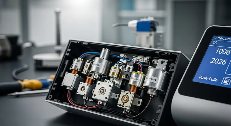
Push-pull solenoid must be equipped with a high-precision guide sleeve to ensure smooth linear movement of the push rod and avoid jamming; the armature is made of wear-resistant alloy material to reduce wear caused by high-frequency push-pull and extend service life; the coil adopts high-temperature resistant enameled wire to improve stability under high-temperature working conditions; the shell is made of flame-retardant and impact-resistant engineering plastic to adapt to the complex indoor and outdoor use environment of attendance devices; at the same time, the sealing design is optimized to prevent dust and water vapor from entering the interior and affecting action reliability.
Chapter 7: Implementation and Commissioning: System Matching and Performance Optimization
In the prototype stage of the attendance device, the implementation and commissioning of the push-pull solenoid play a decisive role in the operation stability and user experience of the entire machine. The following core work needs to be focused on:
7.1. Stroke and Position Calibration
Precisely calibrate the push rod stroke range by adjusting the position of the solenoid mounting bracket, adding or subtracting gaskets, etc., to ensure that the push-pull action is in place but not overshoot: the card is firmly fixed without shaking when locked, and the card ejects to a moderate height (easy for the user to take) when ejected, avoiding problems such as card jamming, insufficient ejection, or excessive ejection and falling caused by stroke deviation.
7.2. Optimization of Energization Time and Drive Logic
Cooperate with software engineers to optimize the energization pulse width and drive logic of the solenoid: adopt the pulse drive mode of “short-time energization to complete the action, and power off after the action is in place”, which can maximize the reduction of coil heating while ensuring the push-pull force, avoid excessive temperature rise caused by long-term full-load energization, and extend the service life of the solenoid; at the same time, set an overcurrent protection mechanism to prevent the coil from being burned due to abnormal current increase.
7.3. Joint Commissioning of Action Timing
Realize the coordinated linkage between the solenoid action and components such as the card swiping module, indicator light, and buzzer: after the card is inserted in place, the sensor triggers a signal, and the solenoid is energized and locked with a delay of 5-10ms (to avoid incomplete card insertion); after reading is completed, the main control board sends a signal, the solenoid is de-energized and released, and the buzzer sounds and the indicator light turns on to remind the user to take the card, ensuring that the mechanical action is accurately synchronized with the identification result.
7.4. Noise Control Optimization
Install silica gel buffer pads at the end of the solenoid push rod and the connection between the shell and the bracket to absorb the impact energy during push-pull and reduce metal collision noise; optimize the flatness of the fitting surface between the armature and the iron core to reduce gap vibration noise; adjust the elastic coefficient of the return spring to avoid impact caused by too fast spring rebound, ensuring that the equipment working noise is controlled below 40dB, adapting to a quiet office environment.
The commissioning process usually requires multiple rounds of coordinated optimization of mechanical structure, electrical control, and software logic to achieve the best overall machine performance.
Chapter 8: Effect Verification: Stability and Reliability Testing
Before mass production, push-pull solenoids must pass systematic verification tests to ensure they meet the requirements of high-frequency and long-term stable operation of attendance devices:
8.1. High-Frequency Action Life Test
Simulate actual use scenarios and conduct more than 100,000 push-pull cycle tests (usually requiring ≥500,000 times), monitor the push-pull force attenuation, armature wear, and coil aging of the solenoid under high-frequency actions, and ensure that its service life matches the entire life cycle of the attendance device.
8.2. Environmental Adaptability Test
Conduct operation tests in simulated environments such as high and low temperatures (-10℃~45℃), high humidity (relative humidity above 85%), and dust, verify the action consistency, response time change, and coil insulation performance of the solenoid, and ensure stable operation in attendance device deployment scenarios in different regions and environments.
8.3. Overall Machine Linkage Reliability Test
Simulate extreme scenarios such as continuous card swiping (e.g., 1000 consecutive card swipes), manual misoperation (reverse card insertion, forced card pulling), and abnormal power failure, verify the action response accuracy, reliable reset capability, and protection mechanism effectiveness of the solenoid, and ensure that the equipment is not damaged and user cards are not retained under fault conditions.
Verification results show that reasonably selected and adjusted push-pull solenoids can significantly reduce the card jamming rate and equipment failure rate, and improve user attendance experience and equipment operation and maintenance efficiency.
Chapter 9: Core Advantages and Disadvantages of Push-Pull Solenoids in Attendance Device Applications
9.1. Core Advantages
Fast response speed: Millisecond-level action response can quickly complete card locking and releasing, avoid user queuing, and improve attendance efficiency;
Simple control logic: Action control can be achieved only through power on/off or pulse signals, without complex drive mechanisms, easy to integrate with the attendance device’s main control system, and reduce development costs;
Compact structure and easy integration: Small in size and light in weight, adapting to the narrow installation space inside the attendance device, and flexible in installation methods (such as bolt fixing, snap connection), facilitating the modular design of the entire machine;
9.2 High reliability and long service life:
Adopt wear-resistant materials and optimized structural design, which can withstand high-frequency action cycles and meet the requirements of long-term stable operation of attendance devices;
Strong safety: Cooperate with a return spring to realize automatic power-off reset, which can automatically release the card in abnormal situations, avoid user property loss, and comply with equipment safety design specifications;
High cost performance: Compared with executive components such as servo motors and stepper motors, push-pull solenoids have a simple structure and low mass production cost, which can significantly reduce the overall cost of attendance devices.
9.3 Core Disadvantages
Limited stroke range: Usually only short-stroke (5-20mm) linear movement can be achieved, which cannot meet the long-distance drive needs in attendance devices, and the application scenarios are limited;
Poor flexibility in push-pull force adjustment: Once selected, the push-pull force is basically fixed, making it difficult to dynamically adjust according to cards of different thicknesses and weights, requiring precise matching of requirements in advance;
9.4 Certain working noise: Although it can be optimized through buffer design, the metal impact and spring rebound during push-pull will still produce slight noise, which may require additional optimization for scenarios with extremely high mute requirements;
9.5 Easy coil temperature rise:
If the drive logic is unreasonable, long-term continuous energization will lead to excessive coil temperature rise, which not only increases power consumption but also may accelerate coil aging and affect service life;
High requirements for installation accuracy: Small deviations in installation position and stroke gap may lead to problems such as action jamming and insecure card locking, increasing production and assembly difficulty and commissioning costs.
Chapter 10: Common Problems and Solutions
Problem 1: The card cannot be locked after insertion, or cannot be ejected after locking Solution: First, check if the solenoid installation position is offset, re-calibrate the stroke and fix it firmly; second, check if the return spring is fatigued or broken, and replace the spring with a matching elastic coefficient; if it is an electrical problem, check if the power supply voltage is stable and if the coil is open, repair the power supply circuit or replace the solenoid.
Problem 2: Excessive working noise of the solenoid during attendance Solution: Install thickened silica gel buffer pads at the end of the solenoid push rod and the connection between the shell and the bracket; grind the fitting surface of the armature and the iron core to improve surface flatness and reduce gap vibration; adjust the preload of the return spring to avoid impact caused by too fast rebound; if the installation is loose, reinforce the bracket and add shock-absorbing washers.
Problem 3: The push-pull force of the solenoid attenuates after high-frequency use, and the card ejects weakly Solution: Disassemble the solenoid, clean internal dust, oil stains and other debris, check if the armature and guide sleeve are worn, and replace the worn parts; optimize the drive logic, extend the short-time energization pulse width (within the allowable temperature rise range) to improve the instantaneous push-pull force; if the coil is aged, directly replace the solenoid of the same model.
Problem 4: The card still cannot be released and remains in the device after power failure Solution: Check if the solenoid type is a model with reset function; if the selection is wrong, replace it with a push-pull solenoid with a return spring; check if the return spring is stuck by foreign objects and clean the stuck debris; check if the solenoid push rod is deformed, correct or replace the push rod.
Problem 5: The coil heats up seriously after long-term work, and even burns out Solution: Optimize the drive logic, strictly adopt the “short-time pulse energization” mode to avoid continuous energization; replace the coil with a thicker wire diameter and higher temperature resistance (such as 155℃ temperature-resistant enameled wire); add an overcurrent protection resistor and a temperature sensor in the circuit to monitor the coil temperature in real time and automatically cut off the power for protection when abnormal.
Problem 6: The anti-disassembly function fails, and no alarm is triggered after the device is disassembled Solution: Check the locking state of the solenoid in the anti-disassembly structure and re-calibrate the locking stroke; check the linkage circuit between the solenoid and the alarm module to repair open circuits or poor contact problems; replace the solenoid with a self-locking function to ensure stable and reliable long-term locking state.
Chapter 11: Experience Summary: Key Points for Application
Combining the engineering practice experience of multiple attendance device projects, the following core application points are summarized to help the efficient implementation of the project:
Stability takes precedence over extreme performance: When selecting, the push-pull force should have a margin of 1.2-1.5 times to avoid premature aging caused by long-term full-load operation, and ensure action repeatability and consistency;
Short-pulse drive is the key to service life: It is essential to adopt the drive mode of “short-time energization to complete the action, and power off after in place”, and reasonably control the energization time (usually 50-200ms), which can significantly reduce coil temperature rise and extend service life;
Mechanical matching determines user experience: The selection of solenoids needs to match the card weight, spring resistance, and stroke space depth. At the same time, attention should be paid to the design of auxiliary structures such as push rods and limit blocks to avoid excellent performance of a single component but insufficient overall coordination;
Power-off safety design cannot be ignored: Push-pull solenoids with return springs must be selected to ensure automatic card release in the event of abnormal power failure. At the same time, add abnormal reset detection logic at the software level to double protect user rights and interests;
Early joint commissioning improves mass production efficiency: Complete the joint commissioning of the solenoid with the mechanical structure and software logic in advance during the prototype stage, focusing on verifying the timing synchronization and noise control effect, to avoid large-scale rectification during mass production;
Adapt to differentiated use scenarios: For high-frequency, dusty environments such as factories, select solenoids with higher sealing levels; for office scenarios, focus on optimizing noise control to improve user experience.
Chapter 12: Conclusion
In modern intelligent attendance devices, although push-pull solenoids are “hidden” executive components, they directly determine the attendance fluency, reliability, and user experience of the device. Through scientific demand analysis, precise selection and design, strict commissioning and verification, as well as advance prediction and solution of common problems, push-pull solenoids can provide a stable, efficient, and cost-effective executive solution for attendance devices. In the future, as attendance devices develop towards thinner, smarter, and lower power consumption, push-pull solenoids will also be upgraded towards miniaturization, low noise, long service life, and low power consumption, further adapting to the development needs of high-end intelligent attendance terminals.