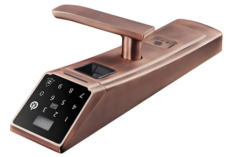
With the continuous improvement of smart homes and intelligent security systems, the technology within door locks has evolved from simple mechanical systems to smart terminals. In modern smart door locks, the technology combines fingerprint recognition, the use of a secret PIN code, IC card technology, Bluetooth connectivity, Wi-Fi connectivity, and cloud technology. While the circuits that recognize and control these systems are highlighted because of the technology involved, the push-pull solenoid valve is another cornerstone actuator that mechanically drives the bolt.
Chapter 1: Introduction
This article provides an exhaustive engineering perspective on implementing push-pull solenoids in intelligent door locks. It explores their locations and methods of application, approaches and designs regarding their structure, methods of implementing and adjusting them, procedures to qualify their reliability, known benefits and limitations, and solutions for any issues. It proves to be an extremely useful resource for designers of locks and manufacturers, as well as electronic-mechanical engineers.
Chapter 2: Needs Analysis and Solution Overview
To identify the needs and requirements for application, there are certain aspects
Smart locks can be found in residential buildings, apartments, hotels, office buildings, or other rental properties. As compared to traditional lock mechanisms, the push-and-pull solenoids in smart locks require more demanding standards.
2.1 Unlocked with a high success ratio and stable performance
Every unlock that is authorized must succeed. Failure may occur in unlocking if the force needed for push/pull is not satisfactory. The unlock success rate that designers set is no less than 99.9%.
2.2 Fast response and precise control
Having completed the fingerprint or password entry process, the lock must then take around 50 to 200 milliseconds to open for a smooth and lag-free user experience.
2.3 Low power consumption and battery compatibility Smart locks are usually battery-driven (four AA batteries or a lithium batteryIt is best if the actuator can move quickly without requiring constant current, thus extending the battery life to 6-12 months.hs.
2.4 High safety and fail-safe behavior In cases involving power outages, undervoltage, or system fault, it is required that the locker remain positively secured against unintentional unlocking. Emergency mechanical unlocking is required to be maintained.
2.5 Compact structure and long service life
Limited internal space necessitates the use of small, lightweight actuators, while frequent daily use requires tens of thousands or hundreds of thousands of reliable cycles over a 5-8 year product lifespan.
Under these comprehensive requirements, push-pull solenoid valves stand out due to their advantages such as simple structure, fast response speed, direct linear motion, and controllable cost, becoming the preferred solution for many smart door lock designs.
Chapter 3: Solution Design: Selection and Structural Configuration of Push-Pull Solenoids
To achieve optimal performance, push-pull solenoids must be carefully matched with the mechanical structure, power system, and control logic of the smart lock.
3.1 Typical job postings
Bolt unlocking and resetting
The push-and-pull solenoids directly drive the bolt to extend and retract, forming the core unlocking function.
Clutch mechanism control
The push-pull action can engage or disengage the mechanical clutch, thereby enabling motor-driven unlocking or allowing manual over-control in an emergency.
Security interlock and anti-tampering mechanism
The solenoid valve can drive a limit block connected to the anti-pry sensor to prevent the bolt from moving when forced in or improperly operated.
3.2 Push- and Pull-Solenoid Type Selection
Push-pull solenoids are frequently employed in smart locks due to their provision of linear motion, rapid actuation, and straightforward on/off control, alongside their compatibility with microcontroller unit (MCU) systems.
Spring return mechanisms are incorporated to ensure automatic resetting following a power interruption, thereby ensuring the lock’s return to a secure state during unforeseen events.
Self-locking solenoid valves, though optional, are utilized in premium smart locks; these valves can maintain their position without a continuous power supply, consequently minimizing energy consumption while preserving the mechanical emergency release capability.
3.3 Important Parameter Design Factors
The design relies on voltage. These may include 6V and 12V DC, and for power related to lithium batteries, 3.7V DC. It is crucial to ensure that it matches the voltage on the control board.
Push and pull forces ranging from 1 N to 8 N result from bolt friction, spring constant forces, and manufacturing alignments. To ensure safety designs at low voltages, it is advisable to adopt a safety factor ranging from 1.2 to 1.5 times the calculated result.
Stroke length—the actual movement of the actuator—rarely varies between 3 and 15 mm and depends precisely on the lock type. Excessive stroke results in mechanical damage to the lock; insufficient stroke will not allow the lock to open fully.
3.4 Energy and Temperature Management
Short pulse drive control is very important. Keeping the excitation duration short, ideally below 50-300 ms, is essential to minimize battery consumption and reduce coil heating, thus avoiding thermal aging of adjacent plastic parts.
Chapter 4: Implementation and Debugging: System-level Matching
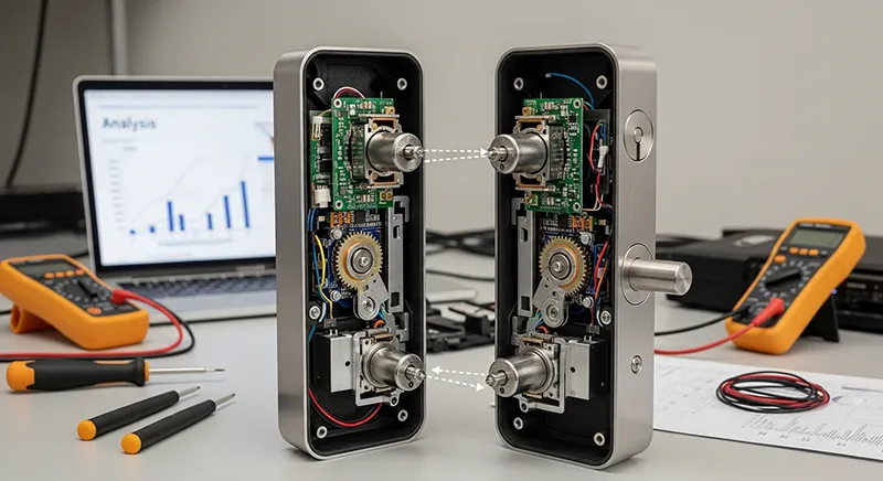
In the process of prototyping and validation, a high degree of collaboration between mechanical, electrical, and software experts is necessary to ensure stable system behavior during mass production.
4.1 Travel and Position Calibration
The mounting brackets, gaskets, and the mechanical limiters are standardized for ensuring the complete movement of the bolt. The expansion due to temperatures in varying conditions must be tested.
4.2 Power-On Timing Optimization
The MCU firmware optimizes pulse width according to the battery voltage to guarantee unlock success while avoiding overheating and unnecessary losses of power.
4.3 Low Voltage Reliability Testing
Tests conducted at 70% of the rated voltage prove that thrust is still adequate and reset performance is reliable even when the battery is drained. 4. Noise & Shock Control Noise reduction methods: – There is a cushioning pad made of silicone located on the end of the push rod. – Optimized armature-core clearance – Correctly positioned return spring With these requirements in mind, the background noise level never goes over 50 decibels, which is appropriate for both home and hotel use.
Chapter 5: Uniqueness Verification
Before mass production, push and pull solenoids go through a verification test.
5.1 Lifecycle and durability
These push and pull solenoids are rated for a minimum of 100,000 cycles and up to 300,000 cycles for the premium units. Through life testing, we monitor the slow deterioration in thrust, wear effects, and any coil resistance drift.
5.2 Ecological adaptability
Temperature range: from -20 to +60 degrees centigrade
Humidity tolerance: at least 90% RH
Tests on dust and pollution are included to ensure good performance irrespective of where the device is installed.
5.3 Abnormal condition validation
The tests that cover power outages, electromagnetic disturbances, spurious triggers, and data signal errors confirm fail-safe lockout under rare situations.
Chapter 6: Advantages and Disadvantages of Push-Pull Solenoids in Intelligent Door Locks
Key benefits
Ultra-fast response for instant unlocking
– Control logic is relatively simple.
– Can be integrated with the control unit at a complexity that is low.
Small size to suit small lock cases.
Low power consumption by pulse control
– Spring return action offers fault safety.
Main disadvantages
- Constrained capacity to respond to dynamic forces
- Requires precise installation
- Mechanical noise
- Depends upon the reliability of the return spring
Performance decreased in cold-weather conditions.
Chapter 7: Common Problems and Engineering Solutions
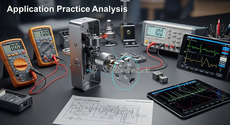
Common problems are failure to unlock at low voltages, too much noise, incomplete resetting, overheating, and degradation in performance at low temperatures. Cures include increasing the force margin, pulse-width tuning, buffer design refinement, better lubrication, replacing springs, and structure recalibration for long-term reliability.
Chapter 8: Summary of Engineering Experience
Core best practices:
Emphasize the reliability rather than the maximum performance. – Design for low-power pulse control The other important areas are the quality of construction, accurate electrical matching, and a close electromagnetic match; however, mechanical matching is generally the first level of concern. -Implementation of predefined safety failure modes – Perform thorough full-condition verification tests Noise refinement, smoothness, and general feel. Conclusion: The push-pull solenoid valve for smart locks plays an important backbone role in guaranteeing unlocking success and products’ overall quality in the aspect of security, reliability, and user experience. It operates stably, efficiently, safely, and economically in actuating through needs analysis, choice, and exhaustive tests with system optimization. As smart door locks move toward slim, energy-efficient, quiet, and long-life designs, so will the push-pull solenoids continue to miniaturize and get efficient in durability and noise for next-generation smart security systems.