The inductor coils have great significance in electronic circuits, and their performance affects various devices and systems. The quality of the production of such inductor coils has a direct impact on the stability of circuits and devices, as well as their life cycle.
For optimal product output, the procedure needs to be monitored meticulously on six major fronts: product details, production planning, product requirements, production procedures, quality controls, and universal problems. Here is the in-depth review of each.
Product specifications are very important because it is the fundamental basis for production. Product specifications
In order to define the performance and application of the inductor coils in various instances, the product specifications are provided.
Chapter 1: Electrical Parameters (Core Performance Indicators)
Value of Inductance: The value and tolerance (such as ±5% and ±10%) provide a controlled storage of energy and filtering.
Rated Current: It encompasses the DC rated current (IDC) and saturation current (ISAT), which is essential in order to avoid overload.
DC Resistance (DCR): Should always be less than the maximum designed value (for example, 0.5 Ω max).
Withstand Voltage: The insulation resistance of the windings to the core (for example, AC 1500V/1min) will
Chapter 2: Structural Parameters (Physical Form and Process Requirements)
Winding Requirements: The wire size (0.1-1.0mm), the number of turns (100-1000), and the winding technique can vary from
Magnetic Core Characteristics: Ferrite, powder iron, or silicon steel core material, along with core shapes such as EE, EI, toroid, and rod, determine the permeability and losses.
Bobbin Factors: These include material (high temperature plastic and ceramic), number of pins, and pitch (for example, 2.54 Overall Dimensions: The use of tolerances (±0.2mm) facilitates
Chapter 3: Environmental Parameters
Operation Temperature Range: Generally, -40~125℃. Must suit car model and industrial use.
Temperature Resistance Class: Specifies the temperature resistance of the wire and bobbin used (Class B: 130℃, Class F: 155℃) thereby having the ability to resist the effects

Chapter 4: Production Planning: Ensuring Delivery and Resource Optimization
Production planning helps balance the demands of orders, production capacity, and material availability.
4.1 Basis for Planning
Customer Orders
Define quantity, delivery schedule, and special requirements.
Material Inventory: Stock raw materials like wire, cores/bobbins, paint.
Equipment Capacity: Assess equipment capacity regarding units of output per hour (Winding machines:
Personnel Allocated:
Verify the availability and qualifications of the operators.
4.2 Content Planning
Capacity Planning
Make a list of the activities performed each day/week (such as
Material Requirements Planning (MRP):
Calculate wire, cores, and paint quantities for production cycles.
Delivery Planning
Define warehousing & shipping schedules
Delivery Planning
Define
Emergency Changes: Contingency plans for materials, equipment, or changes in orders.
Chapter 5: Product Requirements: Quality Objectives
A Product requirements set standards that guide performance, process consistency, and safety standards.
5.1 Performance Requirements
DC Resistance: Meets Design Specs.
Insulation resistance ≥ specified value (such as 100MΩ/
5.2 PROCESS REQUIREMENTS
Winding: No overlap of the wires, no breaks, or damage; correct soldering of the
Dipping: Immersion in a non-bubbly, non-pe
Assembly: Magnetic core assembled to bobbin closely; no deviation from shape and no staining.
5.3 Safety and Reliability
Compliance with the requirements of IEC 61846/UL 1446:Withstand Voltage Tests.Temperature rise tests.
Vibration and shock resistance according to IEC 60068-2-6 (10 to 500 Hz, 10 G
Chapter 6: Production Processes: Standardized Assembly Line
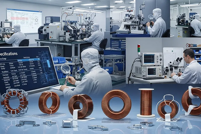
The manufacture of the inductor coils is actually a choreographed procedure to ensure the provision of both quality and the required quantities.
6.1 Material Preparation
This process includes wire cutting to the desired length, stripping the ends of the wires, and checking conductivity.
It is essential that the core and bobbin are inspected, and if the material reveals any cracks or variation of more than 0.1mm, then it
6.2 Winding Process
These are fully automatic and semi-automatic winding machines.
The turns, the rate of the winding (e.g., 500 r/min), and the pitch of the wire are determined.
The positioning of the coil and the fixation of the pins are then evaluated.
6.3 Semi-Finished Product Testing
The inductance, DCR, is measured, and the faulty units are identified.
Process parameters are tuned as and when required.
6.4 Dipping & Curing
The coils are coated in insulating paint for a period of 5-10 minutes.
Cure in oven: Pre-dry at 80℃ for 30 minutes, then cure at 120℃ for 2 hours.
Examine the coating for defects.
6.5 Assembly
The magnetic cores need to be placed inside and retained with adhesive or the use of clamps.
Determine the pin length and pitch (e.g., 5mm or 2.54mm) to suit the PCB.
6.6 Finished Product Testing & Packaging
Check the inductance, DCR, insulation, and appearance of every unit.
Packaged in batches with labels indicating traceability (model no., batch no., inspector’s mark).
Chapter 7: Quality Control: Full-Process Assurance
There are three quality control levels, which ensure defect-free production, and these levels include IQC, IPQC, and
7.1 Incoming Quality Control (IQC)
Investigate enameled wires, cores, bobbins, and paint to check the specifications.
The materials that fail the test are set aside and are then returned to their suppliers.
7.2. In-Process Quality Control
Hourly patrols and first article inspections.
Corrective measures are also immediately done for any defects discovered.
7.3 Final Quality Control (FQC)
Finished products are inspected for conformity to AQL levels (for example, 1.0).
The outbound shipments, packaging, and key performance metrics are validated.
Chapter 8: COMMON PROBLEMS AND SOLUTIONS
Problem
Inductance deviation Wrong turns, core gaps, wire diameter mismatches Recalibrate turns in winding, alter core fit, emphasize wire inspection
DCR too High Thin wire, poor stripping, excess tension Use proper wire, proper stripping, decreased tension
Poor Insulation
Missing dipping, high oven temperature, and dust.
Optimize dipping, calibrate the oven temperature, and better dust control.
Cold/false soldering
Enamel residues, low soldering temperatures and times
Stripping quality check, then adjust the soldering temp to
Magnetic core looseness. Lack of adhesive, improper curing, size differences. Add adhesive, cure accordingly, check core & bobbin fit.
Chapte 8: Summary–Core Logic of Inductor Coil Production
The manufacturing of a good quality inductor coil depends on the slogan, “specifications as foundation, planning as guide, processes as core, quality as guarantee.” On the basis of six significant parameters, a good quality inductor coil can be manufactured within the market requirements.
Chapter 9: FAQ: Common Questions
1. Why is control inductance tolerance a strict control?
Tolerance control affects inductance filtering.Crossing the ±10% level may cause distortion to the signal or a loss of power.
2. Why is an emergency adjustment plan necessary?
“Because things happen. Delays of material, breakdowns of equipment, and personnel issues can all occur. Having a plan keeps things on track and prevents financial obstacles.”
3. Why is dipping and curing so important?
It enhances insulation, hardening of the coil, and protects it from humidity and dust. The absence of this stage may lead to a breakdown of the coil.
4. What is AQL, and how is AQL calculated?
AQL is short for Acceptable Quality Level, which is the highest rate of defects acceptable – this is 1%. The acceptance of a batch is based upon the size of the sample and the number of defects in it.
5. How can you prevent magnetic cores from loosening?
“The trick is: use the proper dimensions, the proper amount of adhesive, and allow it to cure thoroughly. One must also inspect for proper samples before assembly. There can be issues with the inductance or undesired noise sources if the cores are not tightly secured.”